KcsPixelLayout
typedef struct KcsPixelLayout_s {
 	unsigned long				numbOfComp;
 	KcsComponent				component[KcsExtendablePixelLayout];
 } KcsPixelLayout;
|
The KcsPixelLayout structure describes both the source data buffer (the layout of the data to be converted) and the destination data buffer (the receptacle of the converted data) used by KcsEvaluate().
KcsPixelLayout describes a wide variety of pixel layouts in memory including:
-
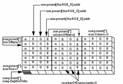
Component-interleaved data -- Color components of a pixel (for example, the red, green, and blue channels of an RGB image) are stored in consecutive memory addresses. (This is also called pixel-interleaved data.) See Figure 3-1 for a detailed diagram of this pixel layout.
-
Row-interleaved data - Image data is stored by row and, within each row, by sub-rows for each component.
-
Planar or band-interleaved data - Image data is stored by component, allowing the components to be stored in independently contiguous memory areas.
KcsPixelLayout can also hold palette color, or a colormap by allowing the application to describe the palette instead of the data itself, as well as allowing the application to describe a single pixel.
If an application stores its image data in a form that is not representable using the KcsPixelLayout structure, the application must convert the data into one of the representable forms before calling the KcsEvaluate() function.
The numbOfComp field specifies the number of components (channels). For example, your application specifies the value 3 for RGB data or 4 for CMYK data.
The component field is an array of base type KcsComponent. It holds the information needed to describe a component (see "KcsComponent " for more information). The KcsExtendableArray constant equals 4 by default. For ease of use, 4 was chosen because it can accommodate most applications, such as CMYK and RGB. It holds the upper limit. Having the open-ended array at the end of the structure allows your application to allocate a larger structure and to extend it past 4, if needed.
Use the following definitions to index the array:
Note - A color space profile (CSP) must exist to support each color space listed above. See "Color Space Profile" for a description of a CSP.
Two structures of type KcsPixelLayout are needed to describe the source data and destination data. Source and destination structures can point to the same data. If the CMM in use does not support this, or if there is some other mismatch between the CMM and the layout structures, KcsEvaluate() returns KCS_LAYOUT_UNSUPPORTED. For example, a CMM may not be able to support the way the source data and the destination data overlap in memory.
Your application can use a pixel layout structure to define any rectangular region of a larger image. Example 3-4 and Figure 3-1 illustrate the component-interleaved, 3-by-7 pixel layout supported in the API.
Example 3-4 uses pseudo-code to show how the pixel layout structure fields are set up.
Example 3-4 Component-Interleaved, 3-by-7 Layout
{
 	numberOfComponents = 3 (Red, Green, and Blue)
 	{
 	component[KcsRGB_R].compType = KcsCompUFixed
 	component[KcsRGB_R].compDepth = 8 (bits per component)
 	component[KcsRGB_R].colOffset = 4 (bytes)
 	component[KcsRGB_R].rowOffset = 12 (bytes)
 	component[KcsRGB_R].maxRow = 7 (pixels)
 	component[KcsRGB_R].maxCol = 3 (pixels)
 	component[KcsRGB_R].bitOffset = 0 (components are byte-aligned)
 	component[KcsRGB_R].addr = (address of red channel)

 	component[KcsRGB_G].compType = KcsCompUFixed
 	component[KcsRGB_G].compDepth = 8 (bits per component)
 	component[KcsRGB_G].colOffset = 4 (bytes)
 	component[KcsRGB_G].rowOffset = 12 (bytes)
 	component[KcsRGB_G].maxRow = 7 (pixels)
 	component[KcsRGB_G].maxCol = 3 (pixels)
 	component[KcsRGB_G].bitOffset = 0 (components are byte-aligned)
 	component[KcsRGB_G].addr = (address of green channel)

 	component[KcsRGB_B].compType = KcsCompUFixed
 	component[KcsRGB_B].compDepth = 8 (bits per component)
 	component[KcsRGB_B].colOffset = 4 (bytes)
 	component[KcsRGB_B].rowOffset = 12 (bytes)
 	component[KcsRGB_B].maxRow = 7 (pixels)
 	component[KcsRGB_B].maxCol = 3 (pixels)
 	component[KcsRGB_B].bitOffset = 0 (components are byte-aligned
 	component[KcsRGB_B].addr = (address of blue channel)
 	}
 }
|
Figure 3-1 24-bit Color Component-Interleaved Data for RGB Pixel Image


