Chapter 1 Processing an Order in a Purchase Order System
This tutorial demonstrates various features of the HTTP Binding Component while creating a purchase order composite application. The project illustrates how to use the HTTP Binding Component to receive and send SOAP messages over HTTP. For more information about the HTTP Binding Component, see the Open ESB web site.
This tutorial uses the following JBI Components:
-
HTTP Binding Component
-
BPEL Service Engine
You can download and review the HTTP Purchase Order Project sample for this tutorial. This is the same project that is created as a result of completing all of the steps in this tutorial.
For more information about working with the NetBeans IDE, see the Docs and Support page on the NetBeans web site.
What you need to know
The following sections provide instructions on how to create, build, and deploy the Purchase Order Project.
What you need to do
These links take you to what you need to know before you create the Purchase Order Project.
Tutorial Requirements
Before you proceed, make sure that you review the requirements in this section.
Prerequisites
This tutorial assumes that you have some basic knowledge of, or programming experience with, the Java language and platform and the NetBeans IDE.
System Requirements
This tutorial assumes that your system meets the requirements specified in the System Requirements topic of the NetBeans 6.1 Release Notes.
Software Needed for the Tutorials
Before you begin, you need to install the following software on your computer: NetBeans IDE 6.1 with SOA and GlassFish V2. These are included in the GlassFish ESB download available from https://open-esb.dev.java.net/Downloads.html .
Project Overview
The purchase order handling system in this scenario is represented by a web service implemented using Sun Java Application Server with the JBI framework.
Scenario Message Flow
-
The web client, using some client-side scripting language such as JavaScript, takes the purchase order information entered into the web form and packages it into a SOAP message. The format of the SOAP message is defined using a WSDL.
-
The SOAP message is sent to a web service endpoint hosted by the HTTP Binding Component.
-
The HTTP Binding Component transforms the SOAP message into a Normalized Message. The Normalized Message is sent to the Normalized Message Router.
-
The Normalized Message Router routes the Normalized Message to the BPEL Service Engine.
-
The BPEL Service Engine interprets the purchase order information and properly invokes other BPEL processes to fulfill the request.
-
The BPEL Service Engine creates a response message in the form of a Normalized Message. The Normalized Message is sent to the Normalized Message Router.
-
The HTTP BC receives the response message and converts it to a SOAP message. The SOAP Message is sent back to the web client as a proper response as defined by the WSDL document.
-
The web client takes the response and creates a human-readable HTML page to notify the user that the purchase order was either accepted or rejected.
The message flow of the Purchase Order scenario is as follows:
Duke's Book Store uses an automated purchase order system with an open interface through which anyone can make a purchase. To accomplish this they use the Java Business Integration framework. Each process is implemented using the BPEL language. Every interface is exposed as a WSDL, with SOAP over HTTP as the underlying messaging and transport.
Core System Pieces
The system's core pieces are the PurchaseOrder interface and the Inventory interface.
-
The PurchaseOrder interface is defined using a WSDL document and has one operation called sendPurchaseOrder. The PurchaseOrder interface is implemented using one BPEL process exposed through SOAP over HTTP. That means that anyone who can send a SOAP message over HTTP to this service can make a purchase.
-
The Inventory interface is defined using a WSDL document and has one operation called isInventoryAvailable. The Inventory interface is implemented using another BPEL process, invoked by the PurchaseOrder service, to determine whether there is sufficient inventory of each book to complete a purchase order. This service is also exposed through SOAP over HTTP. Anyone can make a call to this service, but the main caller of this service is the PurchaseOrder service.
Configuring the Tutorial Environment
Before you can deploy your application, GlassFish V2 must be configured correctly and running.
 To check the status of GlassFish
-
If the Services window is not visible, choose Window -> Services.
-
In the Services window, expand the Servers node.
The Servers node should contain a GlassFish V2 or Sun Java System Application Server subnode. If an application server node does not appear, go to To configure GlassFish.
If a green arrow badge appears on the GlassFish V2 node, the server is running. If a green arrow badge does not appear, go to To start GlassFish.
 To configure GlassFish
-
If the Services window is not visible, choose Window -> Services.
-
In the Services window, right-click the Servers node and choose Add Server from the pop-up menu.
The Add Server Instance dialog box opens.
-
In the Choose Server page, from the Server drop-down list, select GlassFish V2.
-
(Optional) In the Name field, change the default name for the server.
The IDE uses this name to identify the server.
-
Click Next.
The Platform Location Folder page appears.
-
In the Platform Location field, use the Browse button to navigate to and select the installation location of the application server.
The default installation location is different depending on the type of installation and the platform, as shown in the following table.
Platform
Installer
SOA Installation
Tools Bundle Installation
Solaris OS
Linux
root
/opt/SUNWappserver
/opt/SDK
Solaris OS
Linux
user
~/SUNWappserver
~/SDK
Mac OS X
N/A
~/SUNWappserver
~/SDK
Windows
N/A
C:\Sun\AppServer
C:\Sun\SDK
-
Select the Register Local Default Domain radio button and click Next.
-
Enter the user name and password for the domain's administrator.
If you accepted the default values during the installation, the user name is admin and the password is adminadmin.
-
Click Finish.
 To start GlassFish
-
In the Services window, right-click the GlassFish V2 node and choose Start.
-
Wait until the following message appears in the Output window:
Startup complete.
When the server is running, the IDE displays a green arrow badge on the GlassFish V2 node.
Creating a New Project
To create the Purchase Order Sample Project manually, start by creating a new project.
 To Create a New Project
-
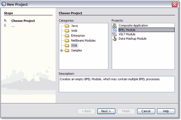
From the main menu, choose File -> New Project.
The New Project dialog box appears.
-
Under Categories select SOA.
-
Under Projects, select BPEL Module, and click Next.
-
From the second page of the wizard, Name and Location, enter HTTP-SOAP-PO-BPEL for Project Name.
-
Click Finish.
The HTTP-SOAP-PO-BPEL project now appears in the Projects window tree.
Creating the XML Schemas
The next step in the Purchase Order sample project is to create the XML schemas
The HTTP-SOAP-PO-BPEL sample project includes two XML schema files. In this section, you create two new XML schema files for your BPEL Module project, inventory.xsd and purchaseOrder.xsd.
Creating the inventory.xsd Schema
The inventory.xsd XML schema enables the BPEL Service Engine to check the current inventory for a requested item.
 To create the inventory.xsd schema
-
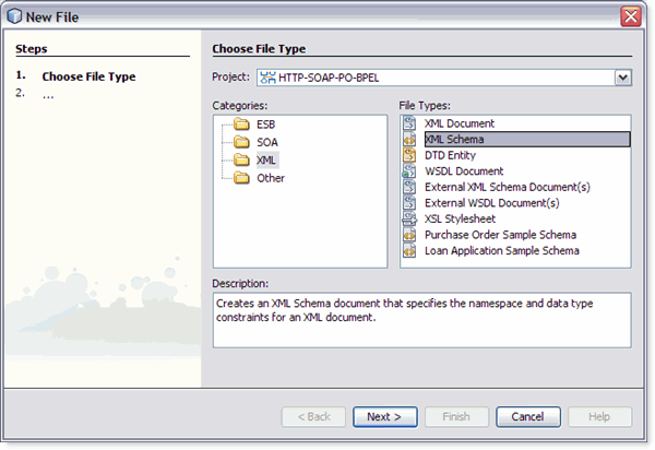
In the Projects window, right-click the HTTP-SOAP-PO-BPEL node and select New -> Other from the pop-up menu.
The New File Wizard appears.
-
In the Categories field, select XML, and in the File Types field, select XML Schema.
-
Click Next.
-
From the second page of the wizard, Name and Location, type inventory as the File Name.
-
Click Finish.
In the Projects window, the Process Files node now contains a subnode named inventory.xsd. The Source Editor contains a tab for the XML schema file, inventory.xsd, with the Schema view open.
 To add a complex type to the XML Schema
-
From the Schema view of the inventory.xsd, right-click the Complex Type node and select Add Complex Type from the pop-up menu.
-
From the Add Complex Type dialog box, click OK. A complex type (newComplexType) is added to the second pane of the Schema window and a sequence node is added to the third pane of the Schema window.
 Add Local Elements to the XML Schema
-
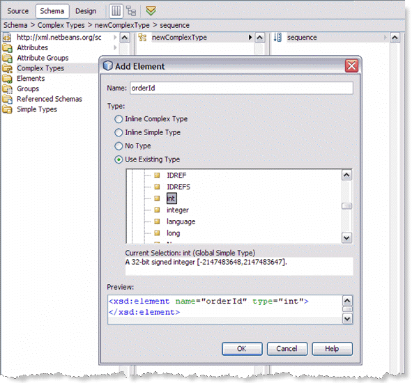
From the Schema window, right-click the sequence node and select Add -> Element from the pop-up menu.
The Add Element dialog box appears.
-
From the Add Element dialog box, do the following:
-
From the Schema window, right-click the sequence node again, and select Add -> Element from the pop-up menu.
The Add Element dialog box appears.
-
From the Add Element dialog box, do the following:
-
From the Schema window, right-click the sequence node again, and select Add -> Element from the pop-up menu.
-
From the Add Element dialog box, do the following:
 To add a global element
-
From the left pane of the Schema window, right-click the Elements node, and select Add -> Element from the pop-up menu.
-
From the Add Element dialog box, do the following:
 To validate the XML Schema
-
From the Schema Editor toolbar, click the Validate XML button. Validation begins.
-
The Outlook window of the IDE displays the validation status. If any errors occur, double-click each error message to see the location of the error and make any necessary corrections. Run validation again to verify corrections.
-
If your validation is successful, click File -> Save All() to save your current changes.
Creating the purchaseOrder.xsd Schema
 To create the purchaseOrder.xsd schema
-
In the Projects window, right-click the HTTP-SOAP-PO-BPEL -> Process Files node and select New -> XML Schema from the pop-up menu.
The XML Schema wizard appears displaying the Name and Location page.
-
From the Name and Location page of the wizard, enter purchaseOrder as the File Name.
-
Click Finish. In the Projects window, the Process Files node now contains a subnode labeled purchaseOrder.xsd . The Source Editor contains a tab for the XML schema file, purchaseOrder.xsd, with the Schema view open.
 To add a complex type to the XML schema
-
From the Schema view of the purchaseOrder.xsd, right-click the Complex Type node and select Add Complex Type from the pop-up menu.
-
From the Add Complex Type dialog box, click OK. A complex type (newComplexType) is added to the second pane of the Schema window and a sequence node is added to the third pane of the Schema window.
 To add local elements to the XML schema
-
From the Schema window, right-click the sequence node and select Add -> Element from the pop-up menu.
The Add Element dialog box appears.
-
From the Add Element dialog box, do the following:
-
In the same manner, add three additional elements with the values shown in the following table:
Name
Type
Current Selection
Type
customerId
Use Existing Type
Built-in Type
int
orderDescription
Use Existing Type.
Built-in Type
String
price
Use Existing Type.
Built-in Type
double
 To add a global element
-
From the left pane of the Schema window, right-click the Elements node, and select Add -> Element from the pop-up menu.
-
From the Add Element dialog box, do the following:
 To validate the XML schema
-
From the Schema Editor's toolbar, click the Validate XML button. Validation begins.
-
If your validation is successful, click File -> Save All to save your current changes.
Creating and Configuring the WSDL Documents
The HTTP-SOAP-PO-BPEL project includes two WSDL documents, one for the inventory service, and one for the purchase order service.
Creating the InventoryService WSDL Document
The InventoryService WSDL document enables the project to check product availability.
 To create the WSDL using the New WSDL Document wizard
-
From the Projects window, right-click the HTTP-SOAP-PO-BPEL project and select New > WSDL Document from the pop-up menu.
The New WSDL Document wizard appears displaying the Name and Location page.
-
Enter InventoryService as the file name.
-
Select Concrete WSDL Document as the WSDL Type, SOAP as the Binding, and Document Literal as the Type. Click Next.
-
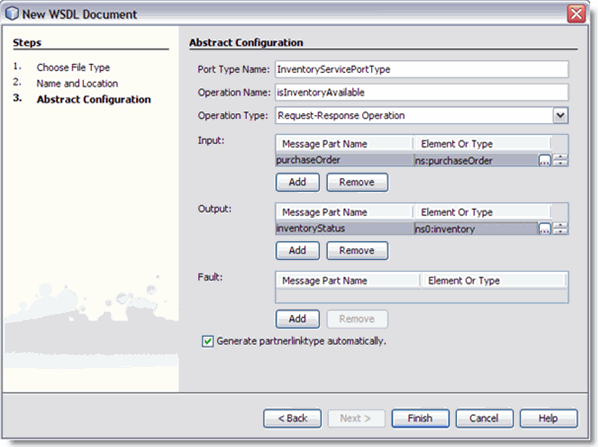
From the Page 3 of the wizard, Abstract Configuration, do the following:
-
For Operation Name, enter isInventoryAvailable.
-
Leave the Operation Type as the default value, Request-Response Operation.
-
For Input, enter purchaseOrder as the Message Part Name.
-
For the input Element or Type value, browse to and select By File -> src/purchaseOrder.xsd -> Elements -> purchaseOrder as the value.
-
For Output, enter inventoryStatus as the Message Part Name.
-
For the output Element or Type value, browse to and select By File -> src/inventory.xsd -> Elements -> inventory as the value.
-
Make sure that the Generate partnerlinktype automatically checkbox is selected, and click Next.
-
From page 4 of the wizard click Finish. The new WSDL is added to the project tree in the Projects window and the WSDL Editor appears in WSDL view.
-
To configure the InventoryService WSDL document:
The InventoryService WSDL document uses the default SOAP WSDL properties. No changes are necessary.
Creating the POService WSDL Document
The POService WSDL document enables the project to send a purchase order.
 To create the POService WSDL document
-
From the Projects window, right-click the HTTP-SOAP-PO-BPEL project and select New -> WSDL Document from the pop-up menu.
-
Enter POService as the file name.
-
Select Concrete WSDL Document as the WSDL Type, SOAP as the Binding, and Document Literal as the Type, and click Next.
-
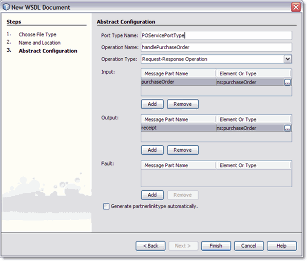
From the page 3 of the wizard, Abstract Configuration, do the following:
-
For Operation Name, enter handlePurchaseOrder.
-
Leave the Operation Type as the default value, Request-Response Operation.
-
For Input, enter purchaseOrder as the Message Part Name.
-
For the input Element or Type value, browse to and select By File -> src/purchaseOrder.xsd -> Elements -> purchaseOrder as the value.
-
For Output, enter receipt as the Message Part Name.
-
For the output Element or Type value, browse to and select By File -> src/purchaseOrder.xsd -> Elements -> purchaseOrder as the value.
-
Make sure that the Generate partnerlinktype automatically checkbox is selected, and click Next.
-
From page 4 of the wizard, click Finish. The new WSDL is added to the project tree in the Projects window and the WSDL Editor appears in WSDL view.
-
To configure the POService WSDL document:
The POService WSDL document uses the default SOAP WSDL properties. No changes are necessary.
Creating the InventoryService BPEL Process
The HTTP-SOAP-PO-BPEL project utilizes two BPEL processes, InventoryService.bpel, which creates a response message with the status of the inventory, and POService.bpel, which creates the purchase order response.
For this example the BPEL Designer's Design view and the BPEL Mapper are used to create the BPEL process.
For more information about using the BPEL Designer, see Developer Guide to BPEL Designer.
 To create the InventoryService BPEL process
-
From the Project window, right-click the HTTP-SOAP-PO-BPEL project's Process Files directory and select New -> BPEL Process from the pop-up menu. The New BPEL Process wizard appears displaying the Name and Location page.
-
From the New BPEL Process wizard, enter InventoryService for the File Name.
-
Click Finish. The BPEL Designer appears containing the new BPEL process.
 To Create the InventoryService business process using
the BPEL Designer
-
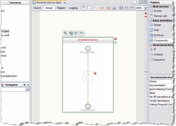
From the Project window, double-click InventoryService.bpel , under the project's Process Files directory. The Design view of the InOutMapper.bpel is displayed graphically in the IDE's BPEL Designer.
-
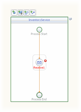
Add a Receive element to the process flow. To do this, drag-and-drop the Receive element from the BPEL Designer Palette to the link between the Process Start and Process End in the designer's process flow.
The IDE provides you with visual clues to show you where you can drop the selection. The Receive element is added to the Design view.
-
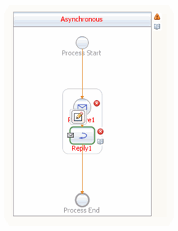
Add a Reply element to the process flow between the Receive1 element and the Process End.
The IDE provides you with visual clues to show you where you can drop the selection. The Reply1 web service is added to the process flow.
-
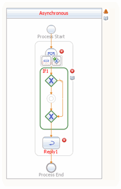
Add an If activity to the process flow diagram between the Receive1 and Reply1 elements. To do this, drag-and-drop the If element from the BPEL Designer Palette to the link between the Receive1 and Reply1 elements in the InventoryService process flow.
-
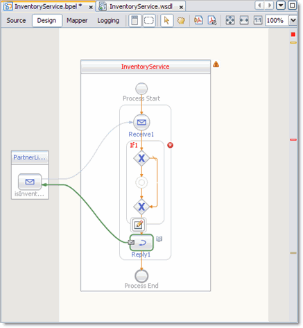
Create a new Partner Link by dragging and dropping the InventoryService.wsdl file from the Projects window to the left side of the BPEL Designer canvas. The IDE provides you with visual clues to show you where you can drop the selection. The PartnerLink1 partner link is added to left side of the BPEL Designer canvas.
-
Set the Receive1 element Partner Link to PartnerLink1 as follows:
-
From the BPEL Designer's Design view, double-click the Receive1 element. The Receive1 [Receive] - Property Editor appears.
-
From the property editor, select PartnerLink1 as the Partner Link value.
-
Click the Input Variable field's Create button. The New Input Variable dialog box appears. Click OK to create the new input variable.
-
Click OK. A partner link is now displayed between the PartnerLink1 and the Receive1 element in the Design view.
-
-
Set the Reply1 element Partner Link to PartnerLink1 as follows:
-
From the BPEL Designer's Design view, click the Reply1 element and click the Reply1 Edit button. The Reply1 [Reply] - Property Editor appears.
-
From the property editor, select PartnerLink1 as the Partner Link value.
-
Click the Output Variable field's Create button. The New Output Variable dialog box appears. Click OK to create the new output variable.
-
Click OK. A partner link is now displayed between the PartnerLink1 and the Reply1 element in the Design view.
-
-
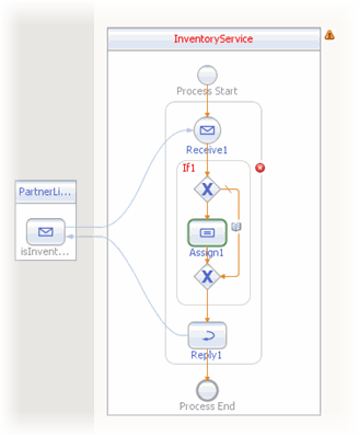
Add an Assign element to the If1 element in the process flow. To do this, drag-and-drop the Assign activity from the BPEL Designer Palette to the link between the beginning and ending node of the If1 element. The Assign1 element is added to the InventoryService process flow.
 To specify the business logic for the InventoryService
BPEL process
-
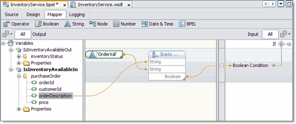
Specify the business logic for the If1 element (not the Assign1 element) from the BPEL Mapper as follows:
-
Select the If1 element in the BPEL Designer's Design view, and click the Designer's Mapper button to open the BPEL Mapper.
The If1 activity is displayed in the BPEL Mapper window.
-
From the BPEL Mapper, expand the nodes in the Output pane.
-
From the BPEL Mapper toolbar's String menu, select Starts With. The Starts With function box appears in the Mapping pane.
-
Map the orderDescription node, under Variables -> IsInventoryAvailableIn -> purchaseOrder in the Output pane of the BPEL Mapper, to the first inbound String node of the Starts With function box. To do this, click on the orderDescription node, and drag your cursor to the String node of the Starts With function box. A link now joins the two nodes.
-
From the BPEL Mapper toolbar's String menu, select String Literal. A String Literal function box appears in the Mapping pane. Enter OrderVal, as the String Literal value.
-
Map the outbound OrderVal node of the String Literal function box to the inbound string2 node of the Starts With function box.
-
Map the outbound Boolean node of the Starts With function box to the Boolean Condition node, under If1 in the Input pane of the BPEL Mapper.
-
-
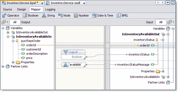
Specify the business logic for the Assign1 element from the BPEL Mapper as follows:
-
From the BPEL Designer's Design view, select the Assign1 element and click the Mapper button to open the BPEL Mapper.
The Assign1 activity is displayed in the BPEL Mapper window.
-
Map orderId, under Variables -> IsInventoryAvailableIn -> purchaseOrder in the Output pane of the BPEL Mapper, to orderId, under Variables -> IsInventoryAvailableOut -> inventoryStatus in the Input pane of the BPEL Mapper.
-
From the BPEL Mapper toolbar's Boolean menu, select and drag Logical True to the Mapping pane. Map the outbound Boolean node of the Logical True function box to inventoryStatus under Variables -> IsInventoryAvailableOut -> inventoryStatus in the Input pane of the BPEL Mapper.
-
From the BPEL Mapper toolbar's String menu, select String Literal. A String Literal function box appears in the Mapping pane. Enter available, as the String Literal value.
-
Map the outbound available node of the String Literal function box to inventoryStatusMessage, under Variables -> IsInventoryAvailableOut -> inventoryStatus in the Input pane of the BPEL Mapper.
-
-
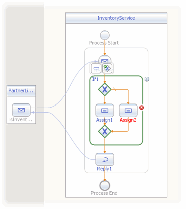
Add an Assign element to the Else of the If1 element in the process flow. To do this, drag-and-drop the Assign activity from the BPEL Designer Palette to the center of the ELSE branch of the If1 element. The Assign2 element is added to the InventoryService process flow.
-
Specify the business logic for the Assign2 element from the BPEL Mapper as follows:
-
Select the Assign2 element in the BPEL Designer's Design view, and click the Designer's Mapper button to open the BPEL Mapper.
The Assign2 activity is displayed in the BPEL Mapper window.
-
From the BPEL Mapper, expand the nodes in the Output and Input panes.
-
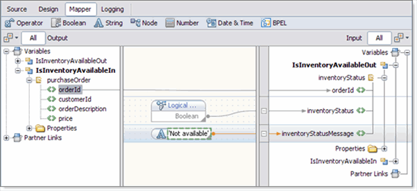
Map orderId, under Variables -> IsInventoryAvailableIn -> purchaseOrder in the Output pane of the BPEL Mapper, to orderId, under Variables -> IsInventoryAvailableOut -> inventoryStatus in the Input pane of the BPEL Mapper.
-
From the BPEL Mapper toolbar's Boolean menu, drag Logical Falseto the center pane of the Designer, inline with the inventoryStatus node under Variables -> IsInventoryAvailableOut -> inventoryStatus in the Input pane of the BPEL Mapper.
The Logical False function box appears in the Mapping pane.
-
Map the outbound Boolean node of the Logical False function box, to the inventoryStatus node under Variables -> IsInventoryAvailableOut -> inventoryStatus in the Input pane of the BPEL Mapper.
-
From the BPEL Mapper toolbar's String menu, select String Literal. Drag the String Literal function box inline with the inventoryStatusmessage node under Variables -> IsInventoryAvailableOut -> inventoryStatus in the Input pane of the BPEL Mapper and enter Not available, as the String Literal value.
-
Map the outbound Not available node of the String Literal function box to inventoryStatusMessage under Variables -> IsInventoryAvailableOut -> inventoryStatus in the Input pane of the BPEL Mapper.
-
-
Validate your new BPEL process as follows:
-
From the BPEL Designer's toolbar, click the Validate XML button. Validation of the BPEL process is performed. The results of the validation are displayed in the NetBeans IDE Output window.
-
If the validation process finds any errors, the Output window lists each error with a link to the point of error in the BPEL Designer. Double-click the hyperlink and refer to the error message for information on how to resolve the error.
-
Once you have resolved any errors, run validation again to ensure that there are no remaining errors or warnings.
-
Click Save All to save your changes.
-
Create the POService BPEL Process
The next step in the Purchase Order sample project is to Create the POService BPEL Process.
The POService.bpel, creates the purchase order response. The BPEL Designer's Design view and the BPEL Mapper are used to create the BPEL process.
 To create the POService BPEL process
-
From the Project window, right-click the HTTP-SOAP-PO-BPEL project and select New -> BPEL Process from the pop-up menu.
-
From the New BPEL Process wizard, enter POService for the File Name.
-
Click Finish.
The POService.bpel file is added to the Projects window, and the BPEL Designer opens containing the new BPEL process.
 To Create the POService business process using the
BPEL Designer
-
From the Project window, right-click the HTTP-SOAP-PO-BPEL project and select New -> BPEL Process from the pop-up menu.
-
From the New BPEL Process wizard, enter POService for the File Name.
-
Click Finish.
The POService.bpel file is added to the Projects window, and the BPEL Designer opens containing the new BPEL process.
-
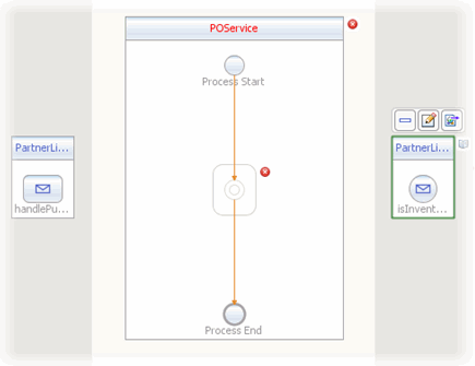
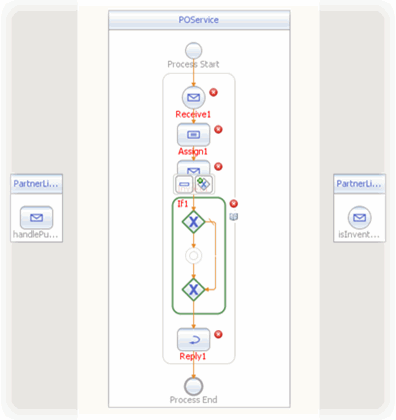
Create a new Partner Link by dragging the POService.wsdl file from the Projects window to the left side of BPEL Designer canvas.
The IDE provides clues to show where to place the POService.wsdl file.
By placing the file on the left side, you create the partnerlink with the roll assigned as “My Role.” This can be verified from the Partnerlink1 Properties Editor.
-
Create another Partner Link, in “Partner Role”, by dragging the InventoryService.wsdl file from the Projects window to the right side of the BPEL Designer canvas.
By placing this file on the right side of the BPEL Designer canvas, you create a partnerlink with the roll assigned as “Partner Roll.” This can be verified from the Partnerlink2 Properties Editor.
Click OK to close the PartnerLink2 Property Editor. The PartnerLink2 partner link is added to the right side of the BPEL Designer canvas.
-
Add a Receive element to the process flow. To do this, drag-and-drop the Receive element from the BPEL Designer Palette to the link between the Process Start and Process End in the designer's process flow. The Receive element is added to the process flow.
-
Add a Reply element to the process flow between the Receive1 element and the Process End. The Reply1 web service is added to the process flow.
-
Add an Invoke element to the process flow between the Receive1 element and the Reply1 element. The Invoke1 web service is added to the process flow.
-
Add an Assign element to the process flow between the Receive1 element and the Invoke1 element. The Assign1 web service is added to the process flow.
-
Add an If element to the process flow between the Invoke1 element and the Reply1 element. The If1 web service is added to the process flow.
-
Set the Receive1 element Partner Link to PartnerLink1 as follows:
-
From the BPEL Designer's Design view, select the Receive1 element and click the Receive1 Edit button. The Receive1 [Receive] - Property Editor appears.
-
From the property editor, select PartnerLink1 as the Partner Link value.
-
Click the Input Variable field's Create button. The New Input Variable dialog box appears. Click OK to create the new input variable.
-
Click OK to close the property editor. A partner link is now displayed from the PartnerLink1 and the Receive1 element in the Design view.
-
-
Set the Reply1 element Partner Link to PartnerLink1 as follows:
-
From the BPEL Designer's Design view, select the Reply1 element and click the Reply1 Edit button. The Reply1 [Reply] - Property Editor appears.
-
From the property editor, select PartnerLink1 as the Partner Link value.
-
Click the Output Variable field's Create button. The New Output Variable dialog box appears. Click OK to create the new output variable.
-
Click OK. A partner link is now displayed between the PartnerLink1 and the Reply1 element in the Design view.
-
-
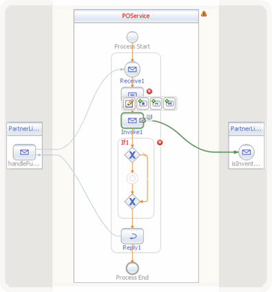
Set the Invoke1 element Partner Link to PartnerLink2 as follows:
-
From the BPEL Designer's Design view, select the Invoke1 element and click the Invoke1 Edit button. The Invoke1 [Invoke] - Property Editor appears.
-
From the property editor, select PartnerLink2 as the Partner Link value.
-
Click the Input Variable field's Create button. The New Input Variable dialog box appears. Click OK to create the new input variable.
-
From the property editor, click the Output Variable field's Create button. The New Output Variable dialog box appears. Click OK to create the new output variable.
-
Click OK. A partner link is now displayed between the PartnerLink2 and the Invoke1 element in the Design view.
-
 To specify the business logic for the POService business
process
-
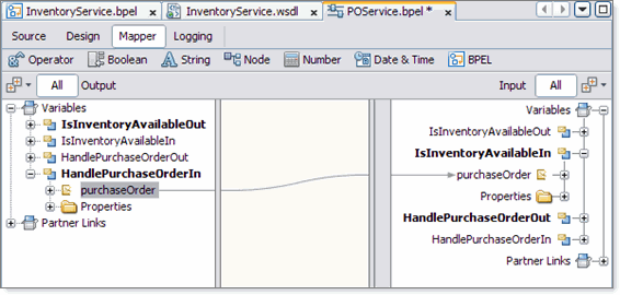
Specify the business logic for the Assign1 element from the BPEL Mapper as follows:
-
Select the Assign1 element in the BPEL Designer's Design view, and click the Designer's Mapper button to open the BPEL Mapper.
The Assign1 activity is displayed in the BPEL Mapper window.
-
From the BPEL Mapper, expand the HandlePurchaseOrderIn node in the Output pane, and the IsInventoryAvailableIn nodes in the Input pane.
-
Map purchaseOrder, under Variables -> HandlePurchaseOrderIn in the Output pane of the BPEL Mapper, to purchaseOrder, under Variables -> IsInventoryAvailableIn in the Input pane of the BPEL Mapper.
-
-
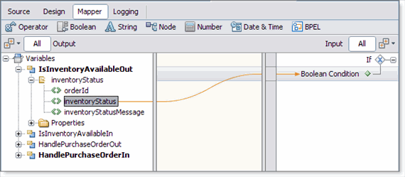
Specify the business logic for the If1 element from the BPEL Mapper as follows:
-
Select the If1 element in the BPEL Designer's Design view, and click the Designer's Mapper button to open the BPEL Mapper.
The If1 activity is displayed in the BPEL Mapper window.
-
Map InventoryStatus, under Variables -> IsInventoryAvailableOut -> InventoryStatus in the Output pane of the BPEL Mapper, to Boolean Condition under If1 in the Input pane of the BPEL Mapper.
-
-
Add an Assign element to the If1 element in the process flow. To do this, drag-and-drop the Assign activity from the BPEL Designer Palette to the link between the beginning and ending node of the If1 element. The Assign2 element is added to the InventoryService process flow.
-
Specify the business logic for the Assign2 element from the BPEL Mapper as follows:
-
Select the Assign2 element in the BPEL Designer's Design view, and click the Designer's Mapper button to open the BPEL Mapper.
The Assign2 activity is displayed in the BPEL Mapper window.
-
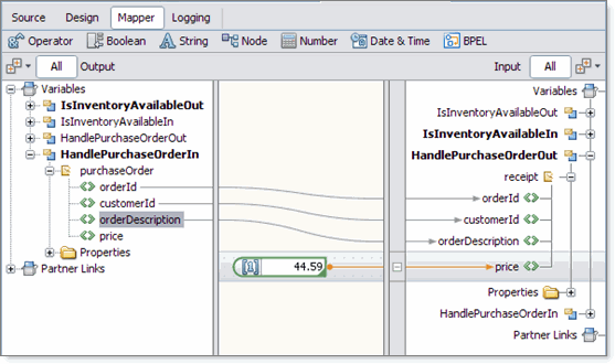
Map orderId, under Variables -> HandlePurchaseOrderIn -> purchaseOrder in the Output pane of the BPEL Mapper, to orderId, under Variables -> HandlePurchaseOrderOut -> receipt in the Input pane of the BPEL Mapper.
-
Map customerId, under Variables -> HandlePurchaseOrderIn -> purchaseOrder in the Output pane of the BPEL Mapper, to customerId, under Variables -> HandlePurchaseOrderOut -> receipt in the Input pane of the BPEL Mapper.
-
Map orderDescription, under Variables -> HandlePurchaseOrderIn -> purchaseOrder in the Output pane of the BPEL Mapper, to orderDescription, under Variables -> HandlePurchaseOrderOut -> receipt in the Input pane of the BPEL Mapper.
-
From the BPEL Mapper toolbar's Number menu, select Number Literal and drag Number Literal to the center pane of the Mapper. A Number Literal function box appears in the Mapping pane. Enter 44.59 as the Number Literal value.
-
Map the outbound 44.59 node of the Number Literal function box, to price, under Variables -> HandlePurchaseOrderOut -> receipt in the right pane of the BPEL Mapper.
-
-
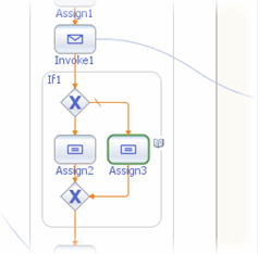
Add an Assign element to the Else of the If1 element in the process flow. To do this, drag-and-drop the Assign activity from the BPEL Designer Palette to the center of the Else branch of the If1 element.
The Assign3 element is added to the InventoryService process flow.
-
Specify the business logic for the Assign3 element from the BPEL Mapper as follows:
-
Select the Assign3 element in the BPEL Designer's Design view, and click the Designer's Mapper button to open the BPEL Mapper.
The Assign3 activity is displayed in the BPEL Mapper window.
-
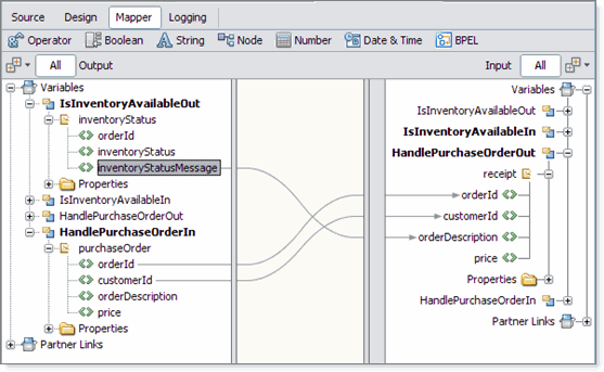
Map orderId, under Variables -> HandlePurchaseOrderIn -> purchaseOrder in the Output pane of the BPEL Mapper, to orderId, under Variables -> HandlePurchaseOrderOut -> receipt in the Input pane of the BPEL Mapper.
-
Map customerId, under Variables -> HandlePurchaseOrderIn -> purchaseOrder in the Output pane of the BPEL Mapper, to customerId, under Variables -> HandlePurchaseOrderOut -> receipt in the Input pane of the BPEL Mapper.
-
Map inventoryStatusMessage, under Variables -> IsInventoryAvailableOut -> inventoryStatus in the Output pane of the BPEL Mapper, to orderDescription, under Variables -> HandlePurchaseOrderOut -> receipt in the Input pane of the BPEL Mapper.
-
-
Validate your new BPEL process as follows:
-
From the BPEL Designer's toolbar, click the Validate XML button. Validation of the BPEL process is performed. The results of the validation are displayed in the NetBeans IDE Output window.
-
If the validation process finds any errors, the Output window lists each error with a link to the point of error in the BPEL Designer. Double-click the hyperlink and refer to the error message for information on how to resolve the error.
-
Once you have resolved any errors, run validation again to ensure that there are no remaining errors or warnings.
-
-
Click Save All to save your changes.
Building the Project
The next step to creating your project is to clean and build it, which means compiling, correcting, and packaging the project's components.
 To compile and package the project
-
In the Projects window, select the HTTP-SOAP-PO-BPEL project node.
-
From the NetBeans Toolbar, click the Clean and Build Main Project icon (hammer and broom).
-
The Output window displays the Ant output and any compilation errors. If any errors are found, double-click each error to go to the error location in the source code. Refer to the error message for information on how to resolve the error.
Creating and Deploying the Composite Application
Before you deploy the BPEL Module project, you must add the JBI module to the deployment project. Deploying the project makes the service assembly available to the application server, which allows its service units to be run.
 To create the Composite Application project
and add the JBI module
-
From the IDE's main menu, choose File -> New Project.
The New Project wizard opens.
-
In the Categories list, select the SOA node.
-
In the Projects list, select the Composite Application
-
Click Next.
-
In the Project Name field, type HTTP-SOAP-PO-JBI .
-
Click Finish.
The Projects window now contains a project node for a Composite Application project called HTTP-SOAP-PO-JBI.
-
In the Projects window, right-click the HTTP-SOAP-PO-JBI project node and select Add JBI Module from the pop-up menu.
The Select Project dialog box opens.
-
Select the HTTP-SOAP-PO-BPEL project you created earlier in this tutorial and click Add Project JAR Files.
The Select Project dialog box closes.
-
In the Projects window, expand the HTTP-SOAP-PO-JBI project node and then expand the JBI Modules node.
Notice that the HTTP-SOAP-PO-BPEL.jar node has been added.
 To build and deploy the Composite Application
-
From the Projects window, right-click the HTTP-SOAP-PO-JBI project and select Build Project from the pop-up menu.
-
The Output window displays the Ant output and any compilation errors. If any errors are found, double-click each error to go to the error location in the source code. Refer to the error message for information on how to resolve the error.
-
Right-click the HTTP-SOAP-PO-JBI project node and select Deploy.
-
The IDE's Output window states BUILD SUCCESSFUL when Deployment has succeeded.
Testing the HTTP Binding Component Sample Project
The Test run feature allows you to test run your processes. BPEL processes are deployed to the BPEL runtime, which manages the process lifecycle.
 To run the HTTP-SOAP-PO-JBI project
-
From the NetBeans IDE Projects window, right click Test under HTTP-SOAP-PO-JBI, and select New Test Case from the pop-up menu.
The New Test Case Wizard appears.
-
From the New Test Case Wizard, type HTTPBC-Test1 as the Test Case Name, and click Next.
-
From the Select the WSDL Document page of the wizard, expand the HTTP-SOAP-PO-BPEL node in the Select the WSDL Document field, and select POService.wsdl . Click Next.
-
From the Select the Operation to Test page of the wizard, select the handlePurchaseOrder operation in the Select the Operation to Test field, and click Finish.
The Input.xml code is displayed in the Source Editor.
-
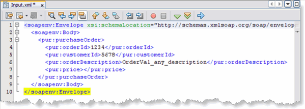
From the Source Editor, make the following changes to the Input.xml code:
-
Change the purchase order ID value in line 4 of the source code to 1234.
-
Change the customer ID value in line 5 of the source code to 5678.
-
Change the purchase order description value in line 6 of the source code to OrderVal_any_description.
-
Delete the value given for purchase price in line 7 of the source code.
Note –To display line numbers, right-click the left frame of the Source Editor and select Show Line Numbers from the pop-up menu.
-
-
Click Save All to save your work.
-
From the IDE's Projects window, right-click HTTPBC-Test1 and select Run.
-
The first time you test run the project, the project fails and an Overwrite Empty Output message appears. Click Yes to save your current output file as the test output.
-
Now that your project has a test output message, run the test again. Right-click HTTPBC-Test1 and select Run.
-
Check the IDEs JUnit Test Results window to verify that the test passed successfully.
-
From the Projects window, double-click Output, under HTTP-SOAP-PO-JBI > Test > TestCase1. The message output, including the purchase price in line 8 of the code, is displayed in the Source Editor.
Note –You can also create a test case to check the Inventory Service by selecting InventoryService.wsdl as the WSDL document, and isInventoryAvailable as the operation.
Project Summary
In this tutorial, you created a purchase order composite application project that uses the HTTP Binding Component. In doing so, you created a BPEL Module project named HTTP-SOAP-PO-BPEL, which includes two XML Schemas, two WSDL documents, and two BPEL processes. Next, you created a composite application project named HTTP-SOAP-PO-JBI, added your HTTP-SOAP-PO-BPEL project to the composite application as a JBI module, and deployed the composite application project. You then tested your composite application.
- © 2010, Oracle Corporation and/or its affiliates

