Using the Partner Link Element
Partner Link elements identify the parties that interact with your business process. Each link is defined by a partner link type and a role name.
Partner Link Types and Roles
The type determines the relationship between a process and its partners by defining the roles played by each service in a conversation. The relationship is further determined by specifying the port type provided by each service to receive messages. Each role specifies one port type in the WSDL file.
Roles determine the conversational aspect of this process or its partner. You use a single role for a synchronous operation as the results are returned using the same operation. You use two roles in an asynchronous operation as the partner role switches during a callback.
It is easy to confuse partner links and partner link types, however:
-
Partner link types and roles are special WSDL extensions defined by the BPEL specification. As such, they are defined in WSDL files, not in the process BPEL file.
-
Partner Link is a BPEL 2.0 element. It is defined in the process BPEL file.
Partner link types are prerequisites to the Partner Link element definition. A Partner Link element can only be defined by referring to a particular partner link type and role which, as mentioned, must be defined in a WSDL file.
Usage
To add the Partner Link element to the BPEL process, do one of the following:
-
Drag the Partner Link element from the Palette to the diagram.
-
Drag a WSDL file node from the same project in the Projects window to the diagram.
-
Drag a WSDL file node from a different project in the Projects window to the diagram.
-
Drag a web service node from an EJB project or a Web Application project in the Projects window to the diagram.
Note: When you drag the web service node, the BPEL Designer retrieves the WSDL file from the Application Server. To successfully retrieve the WSDL file, the Application Server has to be running and the web service project must be deployed.
When you drag the Partner Link element, a WSDL file node, or a web service node to the diagram, the Partner Link Property Editor appears.
The Partner Link Property Editor
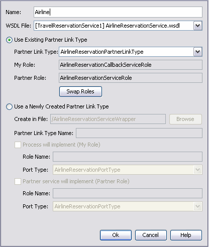
The Partner Link Property Editor dialog box enables you to establish partner links for your BPEL processes.
The Partner Link Property Editor dialog box enables you to establish partner links for your BPEL processes. The Partner Link Property Editor is invoked by double-clicking a Partner Link element on the diagram, or right-clicking the Partner Link element and choosing Edit. The Partner Link Property Editor also appears when you drag the Partner Link element, a WSDL file node, or a web service node to the diagram.
With the Partner Link Property Editor, you can specify:
-
The Partner Link name
-
The WSDL file associated with the Partner Link
Further on you can choose whether to use the existing partner link type or create a new partner link type.
If the WSDL file you selected contains partner link types, the Use Existing Partner Link Type option is selected and the Partner Link Type drop-down list is populated with the partner link types found in the WSDL file. You can use one of the existing partner link types or select the Use a Newly Created Partner Link Type option to create a new partner link type.
If the WSDL file does not contain partner link types, the Use a Newly Created Partner Link Type option is selected.
-
Use Existing Partner Link Type
-
Choose the partner link type from the drop-down list. The My Role and/or Partner Role fields are filled in automatically.
-
To swap the roles of the business process itself (My Role) and the partner (Partner Role), click the Swap Roles button.
-
-
Use a Newly Created Partner Link Type
-
Specify the WSDL file in which to add a partner link type. You can do one of the following:
-
Add the partner link type to the wrapper WSDL file, as suggested by the IDE in the Create in File field by default. If you choose this option, the IDE will automatically create the wrapper WSDL file in your project structure. You can use wrapper WSDL files when the original WSDL file is read-only or when you do not want to modify the original WSDL file. The original WSDL file will be imported to the newly created wrapper WSDL file.
-
Add the partner link type to a WSDL file within your project. Click Browse and locate the WSDL file in which to add the partner link type.
-
-
Specify the partner link type name.
-
Specify the role of the business process itself (My Role) and/or the role of the partner (Partner Role) as follows:
-
Select the appropriate checkbox.
-
Specify the role name.
-
Choose the port type from the drop-down list.
-
-

You can also review and modify the Partner Link's properties in the Properties window invoked by right-clicking the element and choosing Properties.
Partner Link Layout
The partnerlinks are put to the left and to the right margin of the process diagram. Service requestors are placed on the left side, service providers are placed on the right side. To define the role and to choose the appropriate side for each partnerlink the IDE uses the order of roles defined for the partnerLinkType in the WSDL file. The role defined first in the partnerLinkType in the WSDL file is considered to be a service role, the second defined role is considered to be the role for the requestor and callback receiver. If the roles are defined in the reverse order in the wsdl file (the callback receiver role is defined on the first place, and the service role on the second place) then you get the improper partnerlink layout in the BPEL process diagram, though the operation is not damaged. If a partnerlink appears on the wrong side you probably have to go to the WSDL file and swap places for the role definitions in the partnerLinkType.
Dynamic Addressing
Sometimes you need to communicate with partner services whose endpoints are not known beforehand or you need to change an endpoint reference (EPR) during the process execution. The Dynamic Partner Links feature allows you to dynamically assign an endpoint reference to the partnerlink. This means you can use one partner link for communication with several web?services as long as these services have the same interface.
Each partner link has abstract information and concrete information defined. While the abstract information describing web-service interface should be static, the concrete access information such as address and port can be discovered and used dynamically.
Note –
For successful deployment of the process a partner link should be completely defined. It means that when you deploy the project, the WSDL file for the partner link should contain both the abstract and the concrete information for the partner link defined, including address and port, though later the concrete information can be changed independently from the WSDL file.
Note –
The BPEL specification mandates that only the partner EPR can be changed dynamically. In BPEL terms, only the partnerRole of a partnerLink element can have a new value assigned. The myRole value doesn't change after the BPEL has been deployed.
To assign a new EPR to a partner link you can use the standard Assign activity and the BPEL Mapper.
The EPR information can be provided in different ways:
-
Provide it as a literal (type endpoint reference information manually into a literal) and map it to the partner link
-
Use an incoming message to extract the endpoint address
-
Use a variable of the Service Reference type
-
Copy EPR from one partner link to another
If you use an incoming message, an EPR schema should be defined as a part of the message in WSDL. To assign the EPR to a partner link, use the message variable.
 To assign a new endpoint reference to a partner link
from a variable:
-
Create a new Assign activity in the process.
-
Open the BPEL Mapper.
-
In the target tree on the right, find the partner link to which you want to deliver a new concrete part.
-
In the source tree, find a variable containing the new endpoint address.
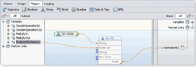
The address of the web-service can be defined in terms of different schemas, and the JBI container requires a special data type called ServiceRefType which is a simple wrapper for any endpoint-describing data type.
To wrap your data:
-
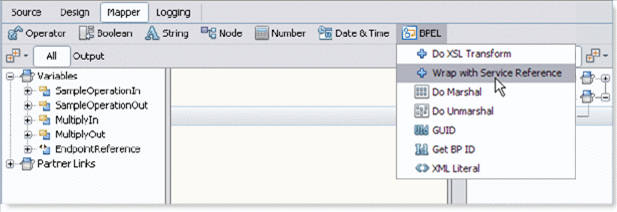
In the mapper toolbar, choose BPEL -> Wrap with Service Reference.

-
This function is a doXslTranform function that uses a predefined XSL-style sheet. A new concrete part is assigned to the partner link.

Note –The runtime supports only schemas included into WS-BPEL 2.0 specification. The WS-Addressing schema is not included in the BPEL specification and as a result it is not supported by the BPEL runtime. When the WS-Addressing schema is used for the first time it is copied from NetBeans global catalog to the BPEL Module project source root and further the project refers to the local copy of the schema. The adressing.xsd schema also appears among the Module's procees files in the Projects window.
-
- © 2010, Oracle Corporation and/or its affiliates
