Creating a BPEL Process Using the BPEL Designer
Now that you have created your XML Schema and WSDL Document, you can create your BPEL process.
 Create the BPEL Process
-
In the Projects window, expand your BPEL module project node, right-click the Process Files node, and choose New -> BPEL Process from the pop-up menu.
The New BPEL Process dialog box appears.

-
Enter a name for the process file name (HelloWorldProcess for this example), and click Finish.
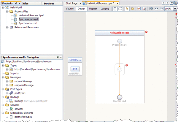
The new BPEL file opens in the Design view of the BPEL Designer.
If the Palette and Properties windows are not displayed in your current view, click Windows -> Reset Windows on the NetBeans menu.

-
Add a partner link to the BPEL Process.
-
In the Projects window, expand your project's Process Files node and select the .wsdl file (Synchronous.wsdl for this example).
-
Drag the .wsdl file from the Projects window to the left side of the Design view canvas.
The IDE provides visual prompts to show you where you can drop the selection.
The BPEL Editor adds a partner link to the canvas.

-
-
Add a Receive activity to the BPEL Process.
-
From the Web Service section of the Palette window, select the Receive activity.
-
Drag the Receive activity to the HelloWorldProcess process box in the Design view canvas, between the Process Start and the Process End activities.
The Receive1 activity is added to the process box.
-
Click the Receive1 activity's Edit icon.
The Receive1 Property Editor appears.
-
On the Main tab, change the value in the Name field to start.
-
From the Partner Link drop-down list, choose PartnerLink1.
The IDE populates the Operation field with operation1.
-
Click the Create button next to the Input Variable Field.
The New Input Variable dialog box appears. Click OK to accept the default values.
-
Click OK to close the Receive1 Property Editor.
The Design view displays the new connection between PartnerLink1 and the Start activity in the process box.

-
-
Add a Reply activity to the BPEL Process.
-
Select the Reply activity in the Web Service section of the Palette. Drag and drop the Reply to the prompt between the Start activity and the Process End activity in the process box on the design view canvas.
A Reply1 activity is added to the design view canvas.
-
Click the Reply1 activity's Edit icon.
The Reply1 Property Editor appears.
-
On the Main tab, change the value in the Name field to End.
-
From the Partner Link drop-down list, choose PartnerLink1.
The IDE populates the Operation field with operation1.
-
To create anew output variable, make sure that Normal Response is selected, and click the Create button next to the Input Variable Field.
The New Input Variable dialog box appears. Click OK to accept the default values.
-
Click OK to close the Reply1 Property Editor.
The Design view displays the new connection between the End activity in the process box and PartnerLink1.

-
-
Add a Reply activity to the BPEL Process.
-
Select the Assign activity in the Basic Activities section of the Palette. Drag and drop the Reply to the prompt between the Start activity and the End activity in the process box on the design view canvas.
The Assign1 activity is added to the design view canvas.
-
Select the Assign1 activity and click the Mapper button on the editors toolbar.
The BPEL Mapper appears.
-
Map the paramA node under Variables -> inputVar -> inputType in the Output pane of the BPEL Mapper, to the paramA node under Variables -> outputVar -> resultType in the Input pane of the Mapper. To do this, select theparamA node under Variables -> inputVar -> inputType in the Output pane, and drag your cursor to the paramA node under Variables -> outputVar -> resultType in the Input pane
This assignment copies the input statement into the output.

-
-
To save your changes click the Save All icon in the IDE menu bar.
- © 2010, Oracle Corporation and/or its affiliates
