Create the POService BPEL Process
The next step in the Purchase Order sample project is to Create the POService BPEL Process.
The POService.bpel, creates the purchase order response. The BPEL Designer's Design view and the BPEL Mapper are used to create the BPEL process.
 To create the POService BPEL process
-
From the Project window, right-click the HTTP-SOAP-PO-BPEL project and select New -> BPEL Process from the pop-up menu.
-
From the New BPEL Process wizard, enter POService for the File Name.
-
Click Finish.
The POService.bpel file is added to the Projects window, and the BPEL Designer opens containing the new BPEL process.
 To Create the POService business process using the
BPEL Designer
-
From the Project window, right-click the HTTP-SOAP-PO-BPEL project and select New -> BPEL Process from the pop-up menu.
-
From the New BPEL Process wizard, enter POService for the File Name.
-
Click Finish.
The POService.bpel file is added to the Projects window, and the BPEL Designer opens containing the new BPEL process.
-
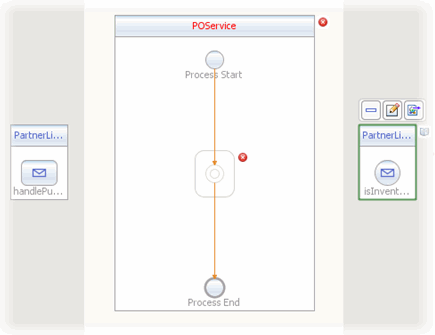
Create a new Partner Link by dragging the POService.wsdl file from the Projects window to the left side of BPEL Designer canvas.
The IDE provides clues to show where to place the POService.wsdl file.
By placing the file on the left side, you create the partnerlink with the roll assigned as “My Role.” This can be verified from the Partnerlink1 Properties Editor.
-
Create another Partner Link, in “Partner Role”, by dragging the InventoryService.wsdl file from the Projects window to the right side of the BPEL Designer canvas.
By placing this file on the right side of the BPEL Designer canvas, you create a partnerlink with the roll assigned as “Partner Roll.” This can be verified from the Partnerlink2 Properties Editor.
Click OK to close the PartnerLink2 Property Editor. The PartnerLink2 partner link is added to the right side of the BPEL Designer canvas.
-
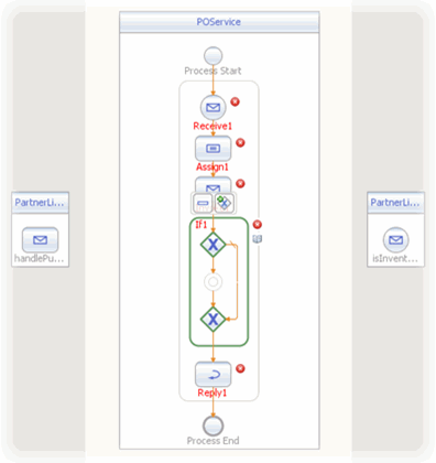
Add a Receive element to the process flow. To do this, drag-and-drop the Receive element from the BPEL Designer Palette to the link between the Process Start and Process End in the designer's process flow. The Receive element is added to the process flow.
-
Add a Reply element to the process flow between the Receive1 element and the Process End. The Reply1 web service is added to the process flow.
-
Add an Invoke element to the process flow between the Receive1 element and the Reply1 element. The Invoke1 web service is added to the process flow.
-
Add an Assign element to the process flow between the Receive1 element and the Invoke1 element. The Assign1 web service is added to the process flow.
-
Add an If element to the process flow between the Invoke1 element and the Reply1 element. The If1 web service is added to the process flow.
-
Set the Receive1 element Partner Link to PartnerLink1 as follows:
-
From the BPEL Designer's Design view, select the Receive1 element and click the Receive1 Edit button. The Receive1 [Receive] - Property Editor appears.
-
From the property editor, select PartnerLink1 as the Partner Link value.
-
Click the Input Variable field's Create button. The New Input Variable dialog box appears. Click OK to create the new input variable.
-
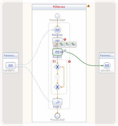
Click OK to close the property editor. A partner link is now displayed from the PartnerLink1 and the Receive1 element in the Design view.
-
-
Set the Reply1 element Partner Link to PartnerLink1 as follows:
-
From the BPEL Designer's Design view, select the Reply1 element and click the Reply1 Edit button. The Reply1 [Reply] - Property Editor appears.
-
From the property editor, select PartnerLink1 as the Partner Link value.
-
Click the Output Variable field's Create button. The New Output Variable dialog box appears. Click OK to create the new output variable.
-
Click OK. A partner link is now displayed between the PartnerLink1 and the Reply1 element in the Design view.
-
-
Set the Invoke1 element Partner Link to PartnerLink2 as follows:
-
From the BPEL Designer's Design view, select the Invoke1 element and click the Invoke1 Edit button. The Invoke1 [Invoke] - Property Editor appears.
-
From the property editor, select PartnerLink2 as the Partner Link value.
-
Click the Input Variable field's Create button. The New Input Variable dialog box appears. Click OK to create the new input variable.
-
From the property editor, click the Output Variable field's Create button. The New Output Variable dialog box appears. Click OK to create the new output variable.
-
Click OK. A partner link is now displayed between the PartnerLink2 and the Invoke1 element in the Design view.
-
 To specify the business logic for the POService business
process
-
Specify the business logic for the Assign1 element from the BPEL Mapper as follows:
-
Select the Assign1 element in the BPEL Designer's Design view, and click the Designer's Mapper button to open the BPEL Mapper.
The Assign1 activity is displayed in the BPEL Mapper window.
-
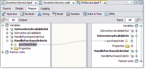
From the BPEL Mapper, expand the HandlePurchaseOrderIn node in the Output pane, and the IsInventoryAvailableIn nodes in the Input pane.
-
Map purchaseOrder, under Variables -> HandlePurchaseOrderIn in the Output pane of the BPEL Mapper, to purchaseOrder, under Variables -> IsInventoryAvailableIn in the Input pane of the BPEL Mapper.
-
-
Specify the business logic for the If1 element from the BPEL Mapper as follows:
-
Select the If1 element in the BPEL Designer's Design view, and click the Designer's Mapper button to open the BPEL Mapper.
The If1 activity is displayed in the BPEL Mapper window.
-
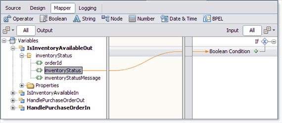
Map InventoryStatus, under Variables -> IsInventoryAvailableOut -> InventoryStatus in the Output pane of the BPEL Mapper, to Boolean Condition under If1 in the Input pane of the BPEL Mapper.
-
-
Add an Assign element to the If1 element in the process flow. To do this, drag-and-drop the Assign activity from the BPEL Designer Palette to the link between the beginning and ending node of the If1 element. The Assign2 element is added to the InventoryService process flow.
-
Specify the business logic for the Assign2 element from the BPEL Mapper as follows:
-
Select the Assign2 element in the BPEL Designer's Design view, and click the Designer's Mapper button to open the BPEL Mapper.
The Assign2 activity is displayed in the BPEL Mapper window.
-
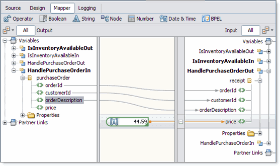
Map orderId, under Variables -> HandlePurchaseOrderIn -> purchaseOrder in the Output pane of the BPEL Mapper, to orderId, under Variables -> HandlePurchaseOrderOut -> receipt in the Input pane of the BPEL Mapper.
-
Map customerId, under Variables -> HandlePurchaseOrderIn -> purchaseOrder in the Output pane of the BPEL Mapper, to customerId, under Variables -> HandlePurchaseOrderOut -> receipt in the Input pane of the BPEL Mapper.
-
Map orderDescription, under Variables -> HandlePurchaseOrderIn -> purchaseOrder in the Output pane of the BPEL Mapper, to orderDescription, under Variables -> HandlePurchaseOrderOut -> receipt in the Input pane of the BPEL Mapper.
-
From the BPEL Mapper toolbar's Number menu, select Number Literal and drag Number Literal to the center pane of the Mapper. A Number Literal function box appears in the Mapping pane. Enter 44.59 as the Number Literal value.
-
Map the outbound 44.59 node of the Number Literal function box, to price, under Variables -> HandlePurchaseOrderOut -> receipt in the right pane of the BPEL Mapper.
-
-
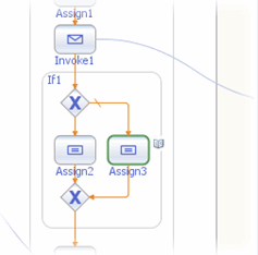
Add an Assign element to the Else of the If1 element in the process flow. To do this, drag-and-drop the Assign activity from the BPEL Designer Palette to the center of the Else branch of the If1 element.
The Assign3 element is added to the InventoryService process flow.
-
Specify the business logic for the Assign3 element from the BPEL Mapper as follows:
-
Select the Assign3 element in the BPEL Designer's Design view, and click the Designer's Mapper button to open the BPEL Mapper.
The Assign3 activity is displayed in the BPEL Mapper window.
-
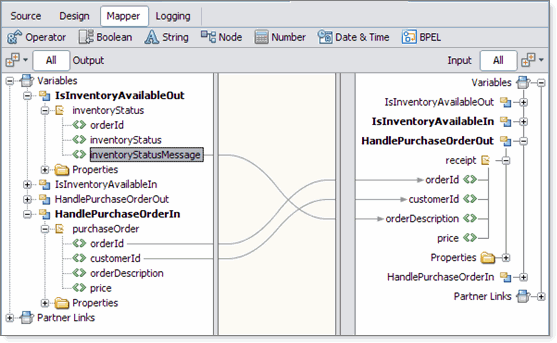
Map orderId, under Variables -> HandlePurchaseOrderIn -> purchaseOrder in the Output pane of the BPEL Mapper, to orderId, under Variables -> HandlePurchaseOrderOut -> receipt in the Input pane of the BPEL Mapper.
-
Map customerId, under Variables -> HandlePurchaseOrderIn -> purchaseOrder in the Output pane of the BPEL Mapper, to customerId, under Variables -> HandlePurchaseOrderOut -> receipt in the Input pane of the BPEL Mapper.
-
Map inventoryStatusMessage, under Variables -> IsInventoryAvailableOut -> inventoryStatus in the Output pane of the BPEL Mapper, to orderDescription, under Variables -> HandlePurchaseOrderOut -> receipt in the Input pane of the BPEL Mapper.
-
-
Validate your new BPEL process as follows:
-
From the BPEL Designer's toolbar, click the Validate XML button. Validation of the BPEL process is performed. The results of the validation are displayed in the NetBeans IDE Output window.
-
If the validation process finds any errors, the Output window lists each error with a link to the point of error in the BPEL Designer. Double-click the hyperlink and refer to the error message for information on how to resolve the error.
-
Once you have resolved any errors, run validation again to ensure that there are no remaining errors or warnings.
-
-
Click Save All to save your changes.
- © 2010, Oracle Corporation and/or its affiliates
