 To Create the InventoryService business process using
the BPEL Designer
-
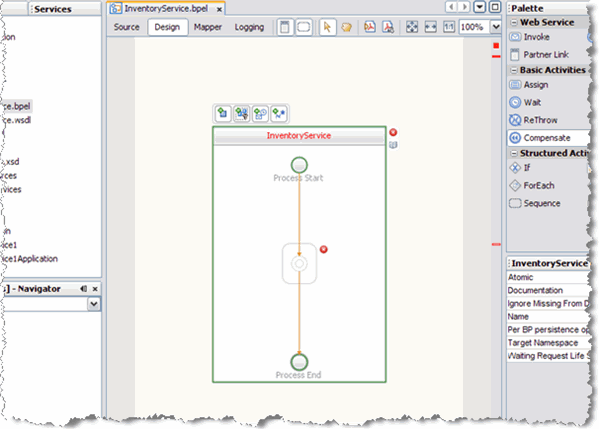
From the Project window, double-click InventoryService.bpel , under the project's Process Files directory. The Design view of the InOutMapper.bpel is displayed graphically in the IDE's BPEL Designer.
-
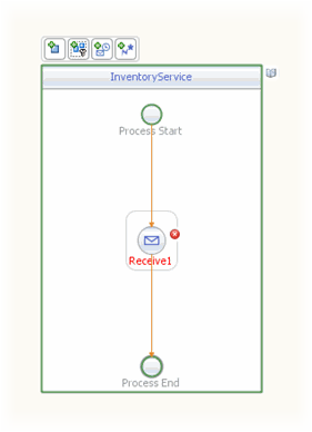
Add a Receive element to the process flow. To do this, drag-and-drop the Receive element from the BPEL Designer Palette to the link between the Process Start and Process End in the designer's process flow.
The IDE provides you with visual clues to show you where you can drop the selection. The Receive element is added to the Design view.
-
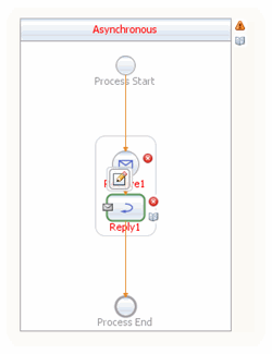
Add a Reply element to the process flow between the Receive1 element and the Process End.
The IDE provides you with visual clues to show you where you can drop the selection. The Reply1 web service is added to the process flow.
-
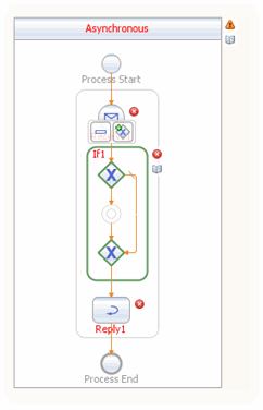
Add an If activity to the process flow diagram between the Receive1 and Reply1 elements. To do this, drag-and-drop the If element from the BPEL Designer Palette to the link between the Receive1 and Reply1 elements in the InventoryService process flow.
-
Create a new Partner Link by dragging and dropping the InventoryService.wsdl file from the Projects window to the left side of the BPEL Designer canvas. The IDE provides you with visual clues to show you where you can drop the selection. The PartnerLink1 partner link is added to left side of the BPEL Designer canvas.
-
Set the Receive1 element Partner Link to PartnerLink1 as follows:
-
From the BPEL Designer's Design view, double-click the Receive1 element. The Receive1 [Receive] - Property Editor appears.
-
From the property editor, select PartnerLink1 as the Partner Link value.
-
Click the Input Variable field's Create button. The New Input Variable dialog box appears. Click OK to create the new input variable.
-
Click OK. A partner link is now displayed between the PartnerLink1 and the Receive1 element in the Design view.
-
-
Set the Reply1 element Partner Link to PartnerLink1 as follows:
-
From the BPEL Designer's Design view, click the Reply1 element and click the Reply1 Edit button. The Reply1 [Reply] - Property Editor appears.
-
From the property editor, select PartnerLink1 as the Partner Link value.
-
Click the Output Variable field's Create button. The New Output Variable dialog box appears. Click OK to create the new output variable.
-
Click OK. A partner link is now displayed between the PartnerLink1 and the Reply1 element in the Design view.
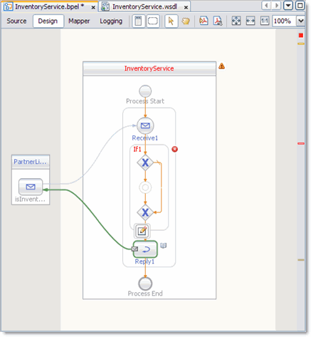
-
-
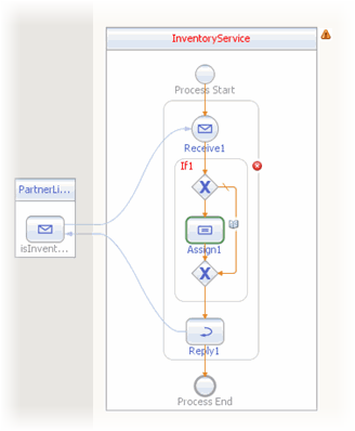
Add an Assign element to the If1 element in the process flow. To do this, drag-and-drop the Assign activity from the BPEL Designer Palette to the link between the beginning and ending node of the If1 element. The Assign1 element is added to the InventoryService process flow.
- © 2010, Oracle Corporation and/or its affiliates
