Chapter 10 Designing a Scaled Deployment
The basic deployment described in Chapter 9, Designing a Basic Deployment assumes that a single Directory Server is enough to satisfy the read and write requirements of your organization. Organizations that have large read or write requirements, that is, several clients attempting to access directory data simultaneously, need to use a scaled deployment.
Generally, the number of searches a Directory Server instance can perform per second is directly related to the number and speed of the server's CPUs, provided there is sufficient memory to cache all data. Horizontal read scalability can be achieved by spreading the load across more than one server. This usually means providing additional copies of the data so that clients can read the data from more than one source.
Write operations do not scale horizontally because a write operation to a master server results in a write operation to every replica. The only way to scale write operations horizontally is to split the directory data among multiple databases and place those databases on different servers.
This chapter describes the different ways of scaling a Directory Server Enterprise Edition deployment to handle more reads and writes. The chapter covers the following topics:
Using Load Balancing for Read Scalability
Load balancing increases performance by spreading the read load across multiple servers. Load balancing can be achieved using replication, Directory Proxy Server, or a combination of the two.
Using Replication for Load Balancing
Replication is the mechanism that automatically copies directory data and changes from one directory server to another directory server. With replication, you can copy a directory tree or subtree that is stored in its own suffix between servers.
Note –
You cannot copy the configuration or monitoring information subtrees.
By replicating directory data across servers, you can reduce the access load on a single machine, improving server response time and providing read scalability. Replicating directory entries to a location close to your users also improves directory response time. Replication is generally not a solution for write scalability.
Basic Replication Concepts
The replication mechanism is described in detail in Chapter 4, Directory Server Replication, in Sun Java System Directory Server Enterprise Edition 6.0 Reference. The following section provides basic information that you need to understand before reviewing the sample topologies described later in this chapter.
Master, Consumer, and Hub Replicas
A database that participates in replication is defined as a replica.
Directory Server distinguishes between three kinds of replicas:
-
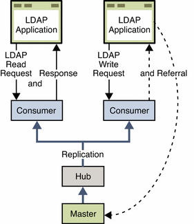
Master or read-write replica. A read-write database that contains a master copy of the directory data. A master replica can process update requests from directory clients. A topology that contains more than one master is called a multi-master topology.
-
Consumer replica. A read-only database that contains a copy of the information in the master replica. A consumer replica can process search requests from directory clients but refers update requests to master replicas.
-
Hub replica. A read-only database (like a consumer replica) that is stored on a Directory Server that supplies one or more consumer replicas.
The following figure illustrates the role of each of these replicas in a replication topology.
Figure 10–1 Role of Replicas in a Replication Topology
Note –
The previous figure is for illustration purposes only and is not necessarily a recommended topology. Directory Server 6.0 supports an unlimited number of masters in a multi-master topology. A master-only topology is recommended in most cases.
Suppliers and Consumers
A Directory Server that replicates to other servers is called a supplier. A Directory Server that is updated by other servers is called a consumer. The supplier replays all updates on the consumer through specially designed LDAP v3 extended operations. In terms of performance, a supplier is therefore likely to be a demanding client application for the consumer.
A server can be both a supplier and a consumer, as in the following situations:
-
In multi-master replication, a master replica is mastered on two different Directory Servers. Each server acts as a supplier and a consumer of the other server.
-
When the server contains a hub replica, the server receives updates from a supplier and replicates the changes to consumers.
A server that plays the role of a consumer only is called a dedicated consumer.
For a master replica, the server must do the following:
-
Respond to update requests from directory clients
-
Maintain historical information and a change log
-
Initiate replication to consumers
The server that contains the master replica is responsible for recording any changes made to the master replica and for replicating these changes to consumers.
For a hub replica, the server must do the following:
-
Respond to read requests
-
Refer update requests to the servers that contain a master replica
-
Maintain historical information and a change log
-
Initiate replication to consumers
For a consumer replica, the server must do the following:
-
Respond to read requests
-
Maintain historical information
-
Refer update requests to the servers that contain a master replica
Multi-Master Replication
In a multi-master replication configuration, data can be updated simultaneously in different locations. Each master maintains a change log for its replica. The changes that occur on each master are replicated to the other servers.
Multi-master configurations have the following advantages:
-
Automatic write failover occurs when one master is inaccessible.
-
Updates can be made on a local master in a geographically distributed environment.
Multi-master replication uses a loose consistency replication model. This means that the same entries may be modified simultaneously on different servers. When updates are sent between the two servers, any conflicting changes must be resolved. Various attributes of a WAN, such as latency, can increase the chance of replication conflicts. Conflict resolution generally occurs automatically. A number of conflict rules determine which change takes precedence. In some cases conflicts must be resolved manually. For more information, see Solving Common Replication Conflicts in Sun Java System Directory Server Enterprise Edition 6.0 Administration Guide.
The number of masters that are supported in a multi-master topology is theoretically unlimited. The number of consumers and hubs is also theoretically unlimited. However, the number of consumers to which a single supplier can replicate depends on the capacity of the supplier server. You can use the SLAMD Distributed Load Generation Engine (SLAMD) to assess the capacity of the supplier server. For information about SLAMD, and to download the SLAMD software, see http://www.slamd.com.
Unit of Replication
The smallest unit of replication is the suffix. The replication mechanism requires one suffix to correspond to one database. You cannot replicate a suffix, or namespace, that is distributed over two or more databases using custom distribution logic. The unit of replication applies to both consumers and suppliers, which means that you cannot replicate two suffixes to a consumer that holds only one suffix.
Change Log
Every server that acts as a supplier maintains a change log. A change log is a record that describes the modifications that have occurred on a master replica. The supplier replays these modifications to its consumers. When an entry is modified, renamed, added, or deleted, a change record that describes the LDAP operation is recorded in the change log.
Replication Agreement
Directory Server uses replication agreements to define how replication occurs between two servers. A replication agreement describes replication between one supplier and one consumer.
A replication agreement identifies the following:
-
The suffix to replicate
-
The consumer server to which the data is pushed
-
The times during which replication can occur
-
The bind DN and credentials that the supplier must use to bind to the consumer
-
How the connection is secured, SSL or client authentication, for example
-
Information about the replication status for this particular agreement
-
Information about replication filtering
Replication Priority
In versions of Directory Server prior to Directory Server6.0, updates were replicated in chronological order. In this version of the product, updates can be prioritized for replication. Priority is a boolean feature, it is on or off. There are no levels of priority. In a queue of updates waiting to be replicated, updates with priority are replicated before updates without priority. In a queue of updates waiting to be replicated, updates with priority are replicated before updates without priority.
The priority rules are configured according to the following parameters:
-
The identity of the client
-
The type of update
-
The entry or subtree that was updated
-
The attributes changed by the update
For more information, see Prioritized Replication in Sun Java System Directory Server Enterprise Edition 6.0 Reference.
Assessing Initial Replication Requirements
A successful replicated directory service requires comprehensive testing and analysis in a production environment. However, the following basic calculation enables you to start designing a replicated topology. The sections that follow use the result of this calculation as the basis of the replicated topology design.
 To Determine Initial Replication Requirements
-
Estimate the maximum number of searches per second that are required at peak usage time.
This estimate can be called Total searches.
-
Test the number of searches per second that a single host can achieve.
This estimate can be called Searches per host. Note that this should be evaluated with replication enabled.
The number of searches that a host can achieve is affected by several variables. Among these are the size of the entries, the capacity of the host, and the speed of the network. A number of third party performance testing tools are available to assist you in conducting these tests. The SLAMD Distributed Load Generation Engine (SLAMD) is an open source Java application designed for stress testing and performance analysis of network-based applications. SLAMD can be used effectively to perform this part of the replication assessment. For information about SLAMD, and to download the SLAMD software, see http://www.slamd.com.
-
Calculate the number of hosts that are required.
Number of hosts = Total searches / Searches per host
Load Balancing With Multi-Master Replication in a Single Data Center
Replication can balance the load on Directory Server in the following ways:
-
By spreading search activities across several servers
-
By dedicating specific servers to specific tasks or applications
Generally, if the Number of hosts calculated in Assessing Initial Replication Requirements is about 16, or not significantly larger, your topology should include only master servers in a fully connected topology. Fully connected means that every master replicates to every other master in the topology.
Note –
The Number of hosts is approximate and depends on the hardware and other details of the deployment.
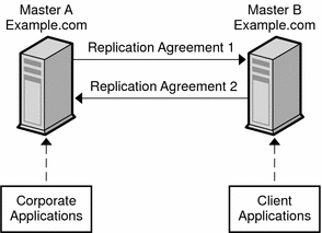
The following figure assumes that the Number of hosts is two. LDAP operations are divided between two master servers, based on the type of client application. This strategy reduces the load that is placed on each server and increases the total number of operations that can be served by the deployment.
Figure 10–2 Using Multi-Master Replication for Load Balancing
For a similar scenario in a global deployment, see Using Multi-Master Replication Over a WAN.
Load Balancing With Replication in Large Deployments
If your deployment requires a Number of hosts significantly larger than 16, you might need to add dedicated consumers to the topology.
The following figure assumes that the Number of hosts is 24 and, for simplicity, shows only a portion of the topology. (The remaining 12 servers would have an identical configuration, with a total of 8 masters and 16 consumers.
Figure 10–3 Using Multi-Master Replication for Load Balancing in a Large Deployment
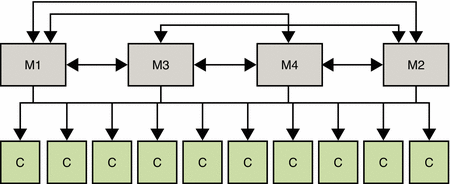
A change log can be enabled on any of these consumers if you need to do the following:
-
Promote the consumer to a master in the event of an outage
-
Perform a binary initialization from a master to any one of the consumers
If the Number of hosts is several hundred, you might want to add hubs to the topology. In such a case, the number of hubs must be an order of magnitude above the number of masters. For example, if your topology requires 200 consumers, you should use approximately 10 hubs and each hub should handle replication to only 20 consumers.
No topology should have the same number of hubs as masters, or the same number of hubs as consumers.
Using Server Groups to Simplify Multi-Master Topologies
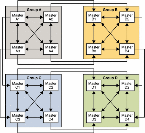
When the Number of hosts is large, the use of server groups can simplify the topology and improve resource usage. In a topology with 16 masters, the use of four server groups, each containing four masters, is easier to manage than 16 fully meshed masters.
Setting up a such a topology involves the following steps:
-
Configure the 16 masters, without any replication agreements.
-
Create four server groups and include four masters in each group.
-
Set up replication agreements between all the masters in a single group.
-
Set up replication agreements between the first master of each group, the second master of each group, and so forth.
The following figure shows the resulting topology.
Figure 10–4 Server Groups in Multi-Master Topologies
Using Directory Proxy Server for Load Balancing
Directory Proxy Server can use multiple servers to distribute the load of a single source of data. Directory Proxy Server can also ensure that if one of the servers is unavailable, the data remains available. Apart from distributing data, Directory Proxy Server provides operation-based load balancing. That is, the server is able to route client operations to a specific Directory Server, based on the type of operation.
Directory Proxy Server supports operation-based load balancing, and a variety of load balancing algorithms that determine how the workload is shared between Directory Servers. For a detailed description of each of these algorithms, see Chapter 25, Directory Proxy Server Load Balancing and Client Affinity, in Sun Java System Directory Server Enterprise Edition 6.0 Reference.
The following figure illustrates how the proportional algorithm is used to balance read load across two servers. Operation-based load balancing routes all writes to Master 1, unless that server fails. On failure all reads and writes are routed to Master 2.
Figure 10–5 Using Proportional and Operation-Based Load Balancing in a Scaled Deployment
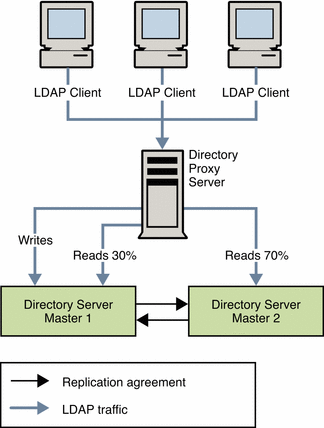
Note that the configuration for load balancing is not recalculated when one server instance fails. You cannot use proportional load balancing to create a “hot standby” server by setting a server's load balancing weight to 0.
Imagine, for example, you have three servers A, B, and C. Proportional load balancing has been configured such that servers A and B each receive 50% of the load. Server C is configured to have 0% of the load as it is designed to be a standby server only. If server A fails, 100% of the load will go to server B automatically. Only if server B also fails, will the load be distributed to server C. So, either the instance participates in load balancing all the time, always ready to take part of the load, or all primary instances have to fail before that server will take any load.
You can achieve something like a hot standby by using the saturation load balancing algorithm and applying a low weight to the standby server. Although the server is not a true standby server, you can configure the algorithm such that requests are distributed to this server only if the primary servers are under heavy load. Effectively if one primary server is disabled, the load on the other primary servers increases to the extent that requests must be distributed to the standby server.
Using Distribution for Write Scalability
Write operations are resource intensive. When a client requests a write operation, the follow sequence of events occurs on the database:
-
The backend database is locked
-
The entry is locked in the database cache
-
The access control check plug-in is called
-
Any backend pre-operation plug-ins are called
-
The database transaction begins
-
The database files are updated
-
The old entry cache is replaced with new data
-
The database transaction is committed
-
Any backend post-operation plug-ins are called
-
The backend database is unlocked
Because of this complex procedure, an increased number of writes can have a dramatic impact on performance.
As an enterprise grows, more client applications require rapid write access to the directory. Also, as more information is stored in a single Directory Server, the cost of adding or modifying entries in the directory database increases. This is because indexes become larger and it takes longer to manipulate the information that the indexes contain.
In some cases, the service level agreements might only be achieved by having all the data cached in memory. However, the data might be too large to fit on a single memory machine
When the volume of directory data increases to this extent, you need to break up the data so that it can be stored in multiple servers. One approach is to use a hierarchy to divide the information. By separating the information into multiple branches based on some criteria, each branch can be stored on a separate server. Each server can then be configured with chaining or referrals to enable clients to access all the information from a single point.
In this kind of division, each server is responsible for only a part of the directory tree. A distributed directory works in a similar way to the Domain Name Service (DNS). The DNS assigns each portion of the DNS namespace to a particular DNS server. In the same way, you can distribute your directory namespace across servers while maintaining, from a client standpoint, a single directory tree.
A hierarchy-based distribution mechanism has certain disadvantages. The main problem is that this mechanism requires that the clients know exactly where the information is. Alternatively, the clients must perform a broad search to find the data. Another problem is that some directory-enabled applications might not have the capability to deal with the information if it is broken up into multiple branches.
Directory Server supports hierarchy-based distribution in conjunction with the chaining and referral mechanisms. However, a distribution feature is also provided with Directory Proxy Server, which supports smart routing. This feature enables you to decide on the best distribution mechanism for your enterprise.
Using Multiple Databases
Directory Server stores data in high-performance, disk-based LDBM databases. Each database consists of a set of files that contains all of the data that is assigned to this set. You can store different portions of your directory tree in different databases. Imagine, for example, that your directory tree contains three subsuffixes, as shown in the following figure.
Figure 10–6 Directory Tree With Three Subsuffixes

The data of the three subsuffixes can be stored in three separate databases as shown in the following figure.
Figure 10–7 Three Subsuffixes Stored in Three Separate Databases

When you divide your directory tree among databases, the databases can be distributed across multiple servers. This strategy generally equates to several physical machines, which improves performance. The three databases in the preceding illustration can be stored on two servers as shown in the following figure.
Figure 10–8 Three Databases Stored on Two Separate Servers

When databases are distributed across multiple servers, the amount of work that each server needs to do is reduced. Thus, the directory can be made to scale to a much larger number of entries than would be possible with a single server. Because Directory Server supports dynamic addition of databases, you can add new databases as required, without making the entire directory unavailable.
Using Directory Proxy Server for Distribution
Directory Proxy Server divides directory information into multiple servers but does not require that the hierarchy of the data be altered. An important aspect of data distribution is the ability break up the data set in a logical manner. However, distribution logic that works well for one client application might not work as well for another client application.
For this reason, Directory Proxy Server enables you to specify how data is distributed and how directory requests should be routed. For example, LDAP operations can be routed to different directory servers based on the directory information tree (DIT) hierarchy. The operations can also be routed based on operation type or on a custom distribution algorithm.
Directory Proxy Server effectively hides the distribution details from the client application. From the clients' standpoint, a single directory addresses their directory queries. Client requests are distributed according to a particular distribution method. Different routing strategies can be associated with different portions of the DIT, as explained in the following sections.
Routing Based on the DIT
This strategy can be used to distribute directory entries based on the DIT structure. For example, entries in the subtree o=sales,dc=example,dc=com can be routed to Directory Server A, and entries in the subtree o=hr,dc=example,dc=com can be routed to Directory Server B.
Routing Based on a Custom Algorithm
In some cases, you might want to distribute entries across directory servers without using the DIT structure. Consider, for example, a service provider who stores entries that represent subscribers under ou=subscribers,dc=example,dc=com. As the number of subscribers grows, there might be a need to distribute them across servers based on the range of the subscriber ID. With a custom routing algorithm, subscriber entries with an ID in the range 1-10000 can be located in Directory Server A, and subscriber entries with an ID in the range 10001-infinity can be located in Directory Server B. If the data on server B grows too large, the distribution algorithm can be changed so that entries with an ID starting from 2000 can be located on a new server, Server C.
Using Directory Proxy Server to Distribute Requests Based on Bind DN
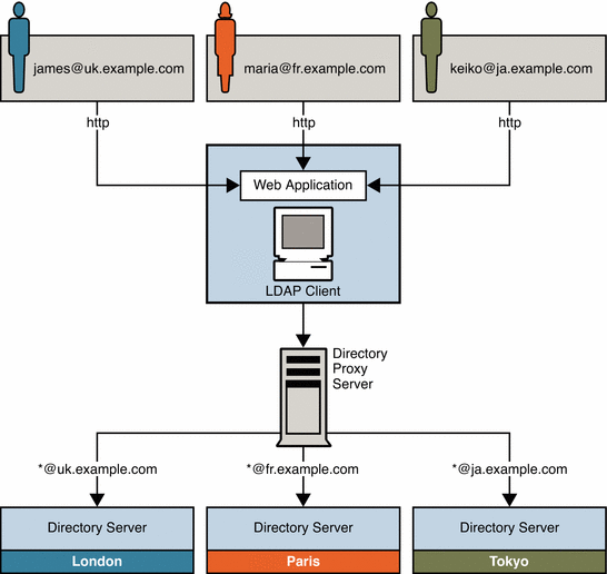
In this scenario, an enterprise distributes customer data between three master servers based on geographical location. Customers that are based in the United Kingdom have their data stored on a master server in London. French customers have their data stored on a master server in Paris. The data for Japanese customers is stored on a master server in Tokyo. Customers can update their own data through a single web-based interface.
Users can update their own information in the directory using a web-based application. During the authentication phase, users enter an email address. email addresses for customers in the UK take the form *@uk.example.com. For French customers, the email addresses take the form *@fr.example.com, and for Japanese customers, *@ja.example.com. Directory Proxy Server receives these requests through an LDAP-enabled client application. Directory Proxy Server then routes the requests to the appropriate master server based on the email address entered during authentication.
This scenario is illustrated in the following figure.
Figure 10–9 Using Directory Proxy Server to Route Requests Based on Bind DN
Distributing Data Lower Down in a DIT
In many cases, data distribution is not required at the top of the DIT. However, entries further up the tree might be required by the entries in the portion of the tree that has been distributed. This section provides a sample scenario that shows how to design a distribution strategy in this case.
Logical View of Distributed Data
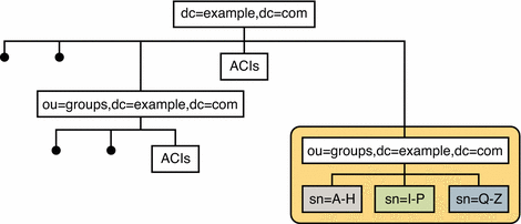
Example.com has one subtree for groups and a separate subtree for people. The number of group definitions is small and fairly static, while the number of person entries is large, and continues to grow. Example.com therefore requires only the people entries to be distributed across three servers. However, the group definitions, their ACIs, and the ACIs located at the top of the naming context are required to access all entries under the people subtree.
The following illustration provides a logical view of the data distribution requirements.
Figure 10–10 Logical View of Distributed Data
Physical View of Data Storage
The ou=people subtree is split across three servers, according to the first letter of the sn attribute for each entry. The naming context (dc=example,dc=com) and the ou=groups containers are stored in one database on each server. This database is accessible to entries under ou=people. The ou=people container is stored in its own database.
The following illustration shows how the data is stored on the individual Directory Servers.
Figure 10–11 Physical View of Data Storage
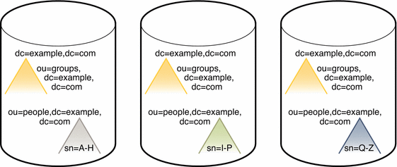
Note that the ou=people container is not a subsuffix of the top container.
Directory Server Configuration for Sample Distribution Scenario
Each server described previously can be understood as a distribution chunk. The suffix that contains the naming context and the entries under ou=groups, is the same on each chunk. A multi-master replication agreement is therefore set up for this suffix across each of the three chunks.
For availability, each chunk is also replicated. At least two master replicas are therefore defined for each chunk.
The following illustration shows the Directory Server configuration with three replicas defined for each chunk. For simplification, the replication agreements are only shown for one chunk, although they are the same for the other two chunks.
Figure 10–12 Directory Server Configuration

Directory Proxy Server Configuration for Sample Distribution Scenario
Client access to directory data through Directory Proxy Server is provided through data views. For information about data views see Chapter 22, Directory Proxy Server LDAP Data Views, in Sun Java System Directory Server Enterprise Edition 6.0 Reference.
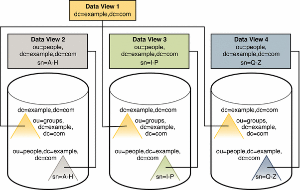
For this scenario, one data view is required for each distributed suffix, and one data view is required for the naming context (dc=example,dc=com) and the ou=groups subtrees.
The following illustration shows the configuration of Directory Proxy Server data views to provide access to the distributed data.
Figure 10–13 Directory Proxy Server Configuration
Considerations for Data Growth
Distributed data is split according to a distribution algorithm. When you decide which distribution algorithm to use, bear in mind that the volume of data might change, and that your distribution strategy must be scalable. Do not use an algorithm that necessitates complete redistribution of data.
A numeric distribution algorithm based on uid, for example, can be scaled fairly easily. If you start with two data segments of uid=0-999 and uid=1000–1999, it is easy to add third segment of uid=2000–2999 at a later stage.
Using Referrals For Distribution
A referral is information returned by a server that tells a client application which server to contact to proceed with an operation request. If you do not use Directory Proxy Server to manage distribution logic, you must define the relationships between distributed data in another way. One way to define relationships is using referrals.
Directory Server supports three ways of configuring how and when referrals are returned:
-
Default referrals. The directory returns a default referral when a client application presents a DN for which the server does not have a matching suffix.
-
Suffix referrals. When an entire suffix has been taken offline for maintenance or security reasons, the server returns the referrals defined by that suffix. Read-only replicas of a suffix also return referrals to the master server when a client requests a write operation.
-
Smart referrals. These referrals are stored on entries within the directory. Smart referrals point to Directory Servers that have knowledge of the subtree whose DN matches the DN of the entry that contains the smart referral.
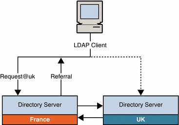
The following figure illustrates how referrals are used to direct clients from the UK to the appropriate server in a global topology. In this scenario, the client application must be able to connect to all the servers in the topology (at the TCP/IP level), to enable it to follow the referral.
Figure 10–14 Using Referrals to Direct Clients to a Specific Server
Using Directory Proxy Server With Referrals
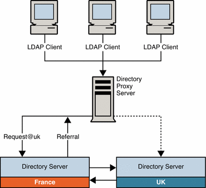
You can use Directory Proxy Server in conjunction with the referral mechanism to achieve the same result. The advantage of using Directory Proxy Server in this regard is that the load and complexity of client applications is reduced. Client applications are only aware of the Directory Proxy Server URL. If the distribution logic is changed, for any reason, this change is transparent to client applications.
The following figure illustrates how the scenario described previously can be simplified with the use of Directory Proxy Server. Client applications always connect to the Proxy Server, which handles the referrals itself.
Figure 10–15 Using Directory Proxy Server With Referrals
- © 2010, Oracle Corporation and/or its affiliates
