Developing Instant Messaging Architectural Strategies
Once you have identified your system performance needs, the next step in sizing your Instant Messaging deployment is to size specific components based on your architectural decisions.
The topics in this section point out sizing considerations when you deploy two-tiered and one-tiered architectures. Using load balancers with Instant Messaging is also discussed.
Two-tiered Instant Messaging Architecture
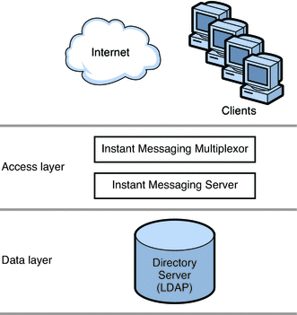
A two-tiered architecture splits the Instant Messaging server deployment into two layers: an access layer and a data layer. In a simplified two-tiered deployment, you might add one or more multiplexors and servers to the access layer. The multiplexor acts as a proxy for users, and relays messages to the Instant Messaging server. The data layer holds the Instant Messaging server database and Directory servers. Figure 20–1 shows a simplified two-tiered Instant Messaging architecture.
Figure 20–1 Simplified Two-tiered Instant Messaging Architecture

Two-tiered architectures have advantages over one-tiered architectures that can impact your sizing decisions. Two-tiered architectures:
-
Are easier to maintain than one-tiered architectures
-
Enable the offloading of load-intensive processes like SSL, message reprocessing
-
Are easier for growth management and you can upgrade your system with limited overall downtime
Sizing Your Multiplexing Services
When you size your multiplexor, the calculation is based on your system load, particularly the number of concurrent connections the multiplexor needs to handle.
In addition, you must:
-
Add CPU or a hardware accelerator for SSL if appropriate.
-
Add memory to the machine if the multiplexor is being configured on it.
-
Add capacity for load balancing and redundancy, if appropriate.
One or more of each type of machine should still handle peak load without a substantial impact to throughput or response time when you plan for redundancy in your deployment.
One-tiered Instant Messaging Architecture
In a one-tiered architecture, there is no separation between access and data layers. The Instant Messaging server, multiplexor, and sometimes the Directory server are installed in one layer. The following figure illustrates the idea.
Figure 20–2 Simplified One-tiered Instant Messaging Architecture

One-tiered architectures have lower up-front hardware costs than two-tiered architectures. However, if you choose a one-tiered architecture, you need to allow for significant maintenance windows.
To size a one-tiered architecture:
-
Add CPU for SSL, if necessary.
-
Add more disks for the increased number of client connections.
-
Add more disks for each multiplexor.
For specific instructions on sizing Instant Messaging components in one-tiered or two-tiered architectures, contact your Sun Client Services representative.
Using Load Balancers With Instant Messaging
Instant Messaging supports the use of load balancers located in front of the Instant Messaging multiplexors. However, you cannot currently use load balancers between the Instant Messaging multiplexors and the Instant Messaging server.
When deploying Instant Messaging as part of a Portal Server/Secure Remote Access deployment, you can locate load balancers between the Secure Remote Access gateway and the Instant Messaging multiplexors.
Note –
If you just need security for the client connection, and not HTTP tunneling, consider using SSL instead of Secure Remote Access. You can configure a secure Instant Messaging client connection by enabling SSL on the multiplexors and locating them outside the firewall.
- © 2010, Oracle Corporation and/or its affiliates
