Example Device Registers
Most of the examples in this manual use a fictitious device that has an 8-bit command and status register (csr), followed by an 8-bit data register. The command and status register is so called because writes to it go to an internal command register, and reads from it are directed to an internal status register.
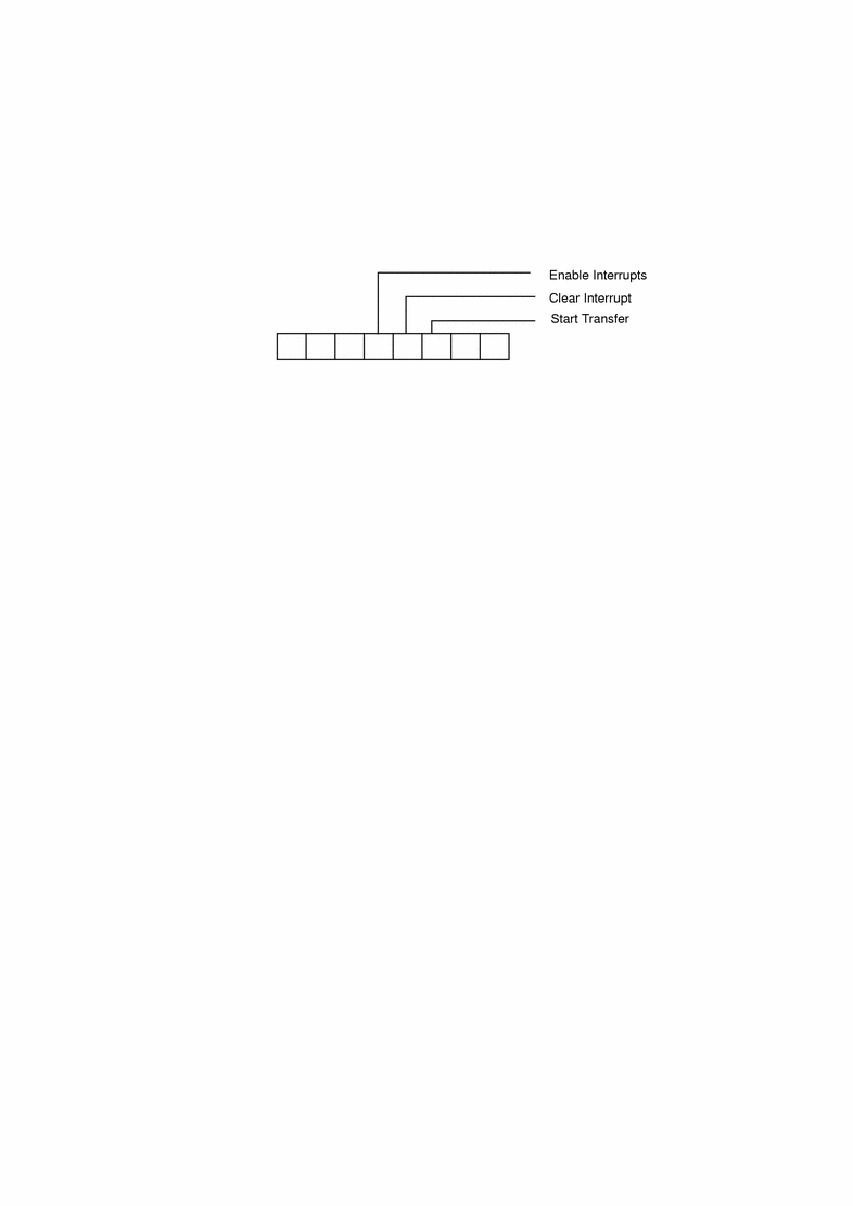
The command register looks like this:

The status register looks like this:

Many drivers provide macros for the various bits in their registers to make the code more readable. The examples in this manual use the following names for the bits in the command register:
	#define	 ENABLE_INTERRUPTS								0x10
 	#define	 CLEAR_INTERRUPT								0x08
 	#define	 START_TRANSFER								0x04
For the bits in the status register, the examples use following macros:
	#define	 INTERRUPTS_ENABLED								0x10
 	#define	 INTERRUPTING								0x08
 	#define	 DEVICE_BUSY								0x04
 	#define	 DEVICE_ERROR								0x02
 	#define	 TRANSFER_COMPLETE								0x01
- © 2010, Oracle Corporation and/or its affiliates
