Chapter 1 Introduction
Communications Services for Access Anywhere is a deployment example of Sun JavaTM Enterprise Systemthat provides secure corporate email and calendar access from any Internet-connected browser, anywhere in the world. Nicknamed EdgeMail, its architecture is patterned after Sun's own internal mail and calendar system.
Instead of distributing mail servers throughout the corporate network, the centralized EdgeMail systems, called complexes, are powerful and highly available racks of machines that provide secure access from both sides of the corporate firewall. An EdgeMail complex is based on the Sun FireTM family of servers, Sun StorEdgeTM disk arrays, and Java Enterprise System (Java ES) software.
This document presents the installation and configuration of an EdgeMail complex. It demonstrates a robust architecture for corporate services that is scalable to global proportions. The complex described here can serve upwards of 10,000 employees and can simply be duplicated across the corporate network to serve more.
This deployment example focuses on the configuration of the hardware and operating system before software installation and the software configuration after installation. It does not document the Java ES installation parameters because they are specific to every installation. This document is intended to provide guidance in dealing with the inherent complexity of large-scale hardware and software systems. It is not a blueprint for implementing an identical system.
1.1 Access Anywhere Architecture
The architecture of an EdgeMail complex is composed of its hardware and software designs.
1.1.1 Hardware Components
The general hardware design of the EdgeMail complex includes the following components:
-
Front-end (FE) servers that receive client requests through a firewall. There are 10 front-end Sun Fire V210 servers.
-
Back-end (BE) servers organized in clustered pairs. There are 4 mail clusters and 2 calendar clusters, for a total of 12 back-end Sun Fire V440 servers.
-
A hardware and operating system management station on a separate Sun Fire V240 server.
-
A software administration station on another separate Sun Fire V240 server.
-
Two redundant storage area networks with three McData Sphereon 4500 fibre channel switches each, for a total of 6 dedicated switches.
-
Six sets of disk arrays, each containing 3 Sun StorEdge 3510 arrays, coupled with 8 Sun StorEdge 3511 arrays, for a total of 26 disk arrays.
-
A large backup server consisting of a Sun Fire V880.
In addition, the EdgeMail complex should include hardware such as the Sun StorEdge L180 or L700 tape libraries for the backup of all data on disk. However, tape libraries are not included in this deployment example.
1.1.2 Racking Diagrams
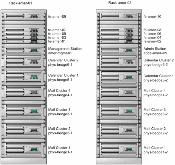
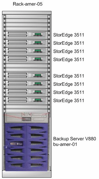
The following racking diagrams give a physical dimension to the size of an EdgeMail complex. All hardware in the complex occupies 5 full-height hardware racks. Such racks are intended to be deployed in a data center where all the power, cooling, and network connectivity needs are provided.
Figure 1–1 Hardware Racks 01 and 02

Figure 1–2 Hardware Racks 03 and 04

Figure 1–3 Hardware Rack 05

1.1.3 Software Design
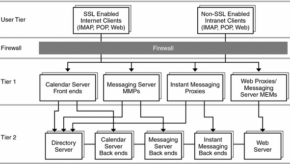
The software design of the EdgeMail system is best described as a multi-tier architecture shown in the following diagram.
Figure 1–4 Multi-Tier Software Design for Access Anywhere

1.1.3.1 User Tier
The users of the EdgeMail system are corporate employees who may be located on the internet or on the corporate intranet. The EdgeMail complex is located behind a firewall to protect both front-end and back-end servers.
From the internet, employees may use any web browser to establish a secure connection to their corporate email and calendar accounts. Security is performed over HTTPS with SSL and certificates to verify user identity without requiring the overhead of VPN (virtual private network).
From inside the corporate network, employees may also use any web browser to view their email and calendar accounts through their familiar portal. Users may also choose to access their accounts through any IMAP email client such as Mozilla. In either case SSL is not used, further reducing overhead.
1.1.3.2 Front-End Tier 1
The front–end tier is in charge of receiving user connections from web browsers and presenting services to the user. The front-end hardware hosts the components that make up tier 1.
The Sun Java System Communications Express and Sun Java System Portal Server components provide the web interface to each employee's email and calendar accounts. Both of these components rely on the Sun Java System Web Server component to provide the web infrastructure to respond to client requests.
1.1.3.3 Back–End Tier 2
The back-end tier is where client requests are processed and business services are performed. The back-end hardware hosts software components that make up tier 2. Here, the Sun Java System Messaging Server component handles all user operations for accessing mailboxes and handling inbound and outbound mail. The Sun Java System Calendar Server handles all interaction between users and their calendars, including email notifications through Messaging Server.
The business services on the back-end hardware also includes the security and identity verification provided by Sun Java System Access Manager and Sun Java System Directory Server.
1.1.3.4 High Availability
In addition to the software components in two tiers, the Access Anywhere design includes Sun Cluster software to provide high availability in case of hardware failure. Each cluster consists of two redundant nodes that run the same software components. Back-end clusters connect to the storage area network (SAN) which includes both redundant switches and redundant disks for fail-safe operation. For more information about the SAN architecture, see 2.2 Storage Area Network (SAN).
The EdgeMail example deploys 4 clusters running Messaging Server and 2 clusters running Calendar Server. System scalability is achieved by increasing the number of clusters according to user needs, which simply involves adding pairs of back-end hosts.
1.2 Naming Conventions
The following naming conventions are used to create physical and logical system names. This document focuses on a single EdgeMail complex installed in a single geographic site. However, complexes are meant to be deployed in several sites to cover all geographic distribution of corporate employees, and system names must allow for them all.
Three elements are used in system names to identify a given complex:
-
The geo is the intended geographic coverage of the complex, for example euro for Europe, amer for North America, soam for South America, and asia for Asia.
-
The complexName itself, which distinguishes between identical systems in separate locations, for example aedge, bedge, and cedge.
-
The network subdomain of the corporate network to which each complex belongs, for example uk.example.com, us.example.com, jp.example.com.
The complex described in this document is bedge in the us.example.com subdomain, serving the amer geographic region.
1.2.1 Physical System Names
Front-end systems have physical names in the following form:
fe-geo-NN.example.com |
Where NN is a two-digit number that sequentially numbers the front-end systems of a given complex, for example fe-amer-01.example.com.
Back-end systems have physical names in the following form:
phys-complexNameN-M.subdomain |
Where N-M are two digits that identify the cluster number and node number, for example phys-bedge3–2.us.example.com is the second node of the third cluster. Because each node of a cluster is on a separate rack, the two digits also identify the server number and the rack number, for example, the physical name above is also the third system in the second rack.
1.2.2 Logical Service Names
Front-end logical service names are used by customers and should be clear and concise. They have the following form:
service-geo.example.com |
Where the front-end service is one of the following:
-
mail for Messaging Server
-
mobile for Wireless
-
book for AddressBook
-
access for HTTP and Communications Express
-
cal for Calendar Server
-
im for Instant Messaging
An example of a logical service name would be mail-amer.example.com that American employees would use as their mail server.
The back-end names for these logical services that are used by the customer have the following form:
complexNameN-serviceM.subdomain |
For example, first node of second mail cluster in the complex can be accessed as bedge2–mail1.us.example.com.
Back-end logical services not used by the customer have names of the following form:
service-geo-NN.subdomain |
Where the back-end service is one of the following:
-
ds for Directory Server, and NN is 01 for a Master, and 02 or 03 for a Replica
-
id for Access Manager and associated Web Server, and NN is 01 or 02, which are load-balanced
For example, ds-amer-01.us.example.com is the master Directory Server for the complex serving the Americas.
- © 2010, Oracle Corporation and/or its affiliates
