2.1 Rack Installation
The following guidelines were adopted to determine mounting locations:
-
Install all Edge hardware with proper mounts in 900 mm depth racks.
-
Separate FE hardware and BE hardware.
-
Place Sun StorEdge 3510 mirrors in different rack cabinets.
-
Place SAN fabrics in different rack units.
-
Minimize number of racks to reduce footprint in datacenter.
-
Consolidate all backup hardware on a single rack.
See 1.1.2 Racking Diagrams for the rack placement of all servers resulting from the guidelines above.
Racks should be installed in a predetermined footprint area of the data center and connected to redundant power distribution units (PDUs). The following specifications give an example of rack footprint and PDU assignments in a data center:
-
Rack 01: location C-01E, connect to PDU-3 circuit 26-28 and PDU-2 circuit 68-70.
-
Rack 02: location C-02E, connect to PDU-3 circuit 25-27 and PDU-2 circuit 67-69.
-
Rack 03: location C-03E connect to PDU-3 circuit 29-31 and PDU-2 circuit 75-77.
-
Rack 04: location C-04E connect to PDU-3 circuit 34-36 and PDU-2 circuit 80-82.
-
Rack 05: location C-05E connect to PDU-4 circuit 80-82 and PDU-3 circuit 17-19.
2.1.1 Component Installation
The following sections list the components in each of the physical servers. All servers of the same type are configured identically.
2.1.1.1 Front-End Sun Fire V210 Servers
The following components are installed in the Sun Fire V210 Servers:
-
DVD-ROM, part number X7410A
-
Sun Crypto Accelerator, part number X7405A
2.1.1.2 Sun Fire V240 Servers
The following components are installed in the Sun Fire V240 servers used for the management and administration stations:
-
DVD-ROM, part number X7410A
-
Sun Crypto Accelerator, part number X7405A
-
2 additional disks, part number XRA-SC1GB-73G10K
2.1.1.3 Back-End Sun Fire V440 Servers
The PCI slot numbers on the back of Sun Fire V440 servers are numbered right to left 0 through 6. Components are installed in V440 systems as per the following table. HBA stands for host bus adapter that allows the server to attach to external storage.
Table 2–1 PCI Slot Components in Sun Fire V440 Servers|
PCI Slot No |
Frequency |
Component |
Description |
|---|---|---|---|
|
0 |
33MHz |
SG-XPCI2FC-QF2 |
PCI Dual HBA |
|
1 |
33MHz |
SG-XPCI2FC-QF2 |
PCI Dual HBA |
|
2 |
66MHz |
SG-XPCI2FC-QF2 |
PCI Dual HBA |
|
3 |
33MHz |
X3151A |
Gigaswift Ethernet |
|
4 |
66MHz |
SG-XPCI2FC-QF2 |
PCI Dual HBA |
|
5 |
66MHz |
X444A |
Quad Gigaswift Ethernet |
2.1.1.4 Backup Sun Fire V880 Server
The following components are installed in the Sun Fire V880 server:
-
DVD-ROM, part number X6168A
-
Sun Crypto Accelerator, part number X7405A
-
6 Additional disks, part number X6756A
2.1.1.5 Sun StorEdge 3510 Arrays
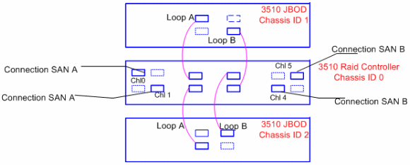
The Sun StorEdge 3510 arrays used for primary storage are grouped as set with 2 of JBOD and 1 Raid Controller unit. The following diagram shows how to connect the 3510 set.
Figure 2–1 Connections Between One Set of 3510 Arrays

2.1.2 Cabling of the Racks
The following sections give an example of cabling guidelines. Details such as cabling are important to specify in your hardware plan to avoid any errors during installation. The following examples give typical information about cabling in a data center.
2.1.2.1 Power Cables
-
Power distribution units (PDUs) and circuits are associated with the location of a rack, as shown i n 2.1 Rack Installation. Access to PDU cirtcuits should be under or adjacent to labeled floor tiles.
-
Power is in a bar (vs power whip) with two rows, one for each PDU.
-
Circuit sockets are on the same row as their associated PDU label. Circuit label is either above or below the actual circuit socket.
2.1.2.2 Patch Panel
-
Copper harmonica patch panels are labeled under the floor.
-
Convention to follow: RED is for network; BLACK is for console.
2.1.2.3 Fiber Connections
-
Patch panels for fiber connections are located under the floor tiles and labeled on the ttile or on the patch panels themselves.
-
Switch fiber patch panels are on right side of switch location. May need to reverse the fibers at the switch patch panels if you do not have connectivity.
-
You will need to connect fiber from switch patch panel over to switches once ports are assigned.
2.1.2.4 Color Conventions
-
No drooping cables or fiber. Cables of correct length need to be used in all racking.
-
Outside corporate network is purple (most cables on the network rack will be purple because most of our servers are outside).
-
Backup is yellow.
-
Inside the corporate network is green.
-
Network cables can be white or gray between server and below floor cable harmonica and need to be purple in the telecom rack, cat 5e plenum rated.
-
Console cables need to be blue for both telecom rack and server to below floor cable harmonica, cat 5e plenum rated.
-
All network, console, and fiber cables need to be labeled with cable length in the middle. Server name, Harmonica port, switch name and blade/port info on both ends of network and console connections. Fiber connections need from and to footprint locations, device names, and board/slot info on both ends.
- © 2010, Oracle Corporation and/or its affiliates
