Chapter 12 Designing a Highly Available Deployment
High availability implies an agreed minimum “up time” and level of performance for your directory service. Agreed service levels vary from organization to organization. Service levels might depend on factors such as the time of day systems are accessed, whether or not systems can be brought down for maintenance, and the cost of downtime to the organization. Failure, in this context, is defined as anything that prevents the directory service from providing this minimum level of service.
This chapter covers the following topics:
Availability and Single Points of Failure
Directory Server Enterprise Edition deployments that provide high availability can quickly recover from failures. With a high availability deployment, component failures might impact individual directory queries but should not result in complete system failure. A single point of failure (SPOF) is a system component which, upon failure, renders an entire system unavailable or unreliable. When you design a highly available deployment, you identify potential SPOFs and investigate how these SPOFs can be mitigated.
SPOFs can be divided into three categories:
-
Hardware failures, for example, server crashes, network failures, power failures, or disk drive crashes
-
Software failures, for example, Directory Server or Directory Proxy Server crashes
-
Database corruption
Mitigating SPOFs
You can ensure that failure of a single component does not cause an entire directory service to fail by using redundancy. Redundancy involves providing redundant software components, hardware components, or both. Examples of this strategy include deploying multiple, replicated instances of Directory Server on separate hosts, or using redundant arrays of independent disks (RAID) for storage of Directory Server databases. Redundancy with replicated Directory Servers is the most efficient way to achieve high availability.
You can also use clustering to provide a highly available service. Clustering involves providing pre-packaged high availability hardware and software. An example of this strategy is deploying Sun Cluster hardware and software.
Deciding Between Redundancy and Clustering
The remainder of this chapter describes in more detail the use of redundancy and clustering to ensure high availability. This section summarizes the advantages and disadvantages of each solution.
Advantages and Disadvantages of Redundancy
The more common approach to providing a highly available directory service is to use redundant server components and replication. Redundant solutions are usually less expensive and easier to implement than clustering solutions. These solutions are also generally easier to manage. Note that replication, as part of a redundant solution, has numerous functions other than availability. While the main advantage of replication is the ability to split the read load across multiple servers, this advantage causes additional overhead in terms of server management. Replication also offers scalability on read operations and, with proper design, scalability on write operations, within certain limits. For an overview of replication concepts, see Chapter 4, Directory Server Replication, in Sun Java System Directory Server Enterprise Edition 6.0 Reference.
During a failure, a redundant system might provide poorer availability than a clustering solution. Imagine, for example, an environment in which the load is shared between two redundant server components. The failure of one server component might put an excessive load on the other server, making this server respond more slowly to client requests. A slow response might be considered a failure for clients that rely on quick response times. In other words, the availability of the service, even though the service is operational, might not meet the availability requirements of the client.
Advantages and Disadvantages of Clustering
The main advantage of a clustered solution is automatic recovery from failure, that is, recovery without user intervention. Disadvantages of clustering are complexity and inability to recover from database corruption.
In a clustered environment, the cluster uses the same IP address for Directory Server and Directory Proxy Server, regardless of which cluster node is actually running the service. That is, the IP address is transparent to the client application. In a replicated environment, each machine in the topology has its own IP address. In this case, Directory Proxy Server can be used to provide a single point of access to the directory topology. The replication topology is therefore effectively hidden from client applications. To increase this transparency, Directory Proxy Server can be configured to follow referrals and search references automatically. Directory Proxy Server also provides load balancing and the ability to switch to another machine when one fails.
How Redundancy and Clustering Handle SPOFs
In terms of the SPOFs that are described at the beginning of this chapter, redundancy and clustering handle failure in the following ways:
-
Single hardware failure. In a clustered environment, this kind of failure has no impact on the directory service. Only multiple hardware failures impact the service in a cluster.
A single hardware failure is fatal to a machine that is not in a clustered environment. Therefore, even if you have redundant hardware, manual intervention is required to repair the failure.
-
Directory Server or Directory Proxy Server failure. In a clustered environment, the server is automatically restarted. Software failure must occur multiple times in quick succession to trigger the service group to switch to another node in the cluster. This handling of a software failure is also true in a redundant environment.
-
Database corruption. A cluster cannot survive this kind of failure. Depending on the architecture, a redundant solution should be able to survive database corruption.
Redundancy at the Hardware Level
This section provides basic information about hardware redundancy. Many publications provide comprehensive information about using hardware redundancy for high availability. In particular, see “Blueprints for High Availability” published by John Wiley & Sons, Inc.
Hardware SPOFs can be broadly categorized as follows:
-
Network failures
-
Failure of the physical servers on which Directory Server or Directory Proxy Server are running
-
Load balancer failures
-
Storage subsystem failures
-
Power supply failures
Failure at the network level can be mitigated by having redundant network components. When designing your deployment, consider having redundant components for the following:
-
Internet connection
-
Network interface card
-
Network cabling
-
Network switches
-
Gateways and routers
You can mitigate the load balancer as an SPOF by including a redundant load balancer in your architecture.
In the event of database corruption, you must have a database failover strategy to ensure availability. You can mitigate against SPOFs in the storage subsystem by using redundant server controllers. You can also use redundant cabling between controllers and storage subsystems, redundant storage subsystem controllers, or redundant arrays of independent disks.
If you have only one power supply, loss of this supply could make your entire service unavailable. To prevent this situation, consider providing redundant power supplies for hardware, where possible, and diversifying power sources. Additional methods of mitigating SPOFs in the power supply include using surge protectors, multiple power providers, and local battery backups, and generating power locally.
Failure of an entire data center can occur if, for example, a natural disaster strikes a particular geographic region. In this instance, a well-designed multiple data center replication topology can prevent an entire distributed directory service from becoming unavailable. For more information, see Using Replication and Redundancy for High Availability.
Redundancy at the Software Level
Failure in Directory Server or Directory Proxy Server can include the following:
-
Excessive response time
-
Write overload
-
Maximized file descriptors
-
Maximized file system
-
Poor storage configuration
-
Too many indexes
-
-
Read overload
-
Cache issues
-
CPU constraints
-
Replication issues
-
Synchronicity
-
Replication propagation delay
-
Replication flow
-
Replication overload
-
-
Large wildcard searches
These SPOFs can be mitigated by having redundant instances of Directory Server and Directory Proxy Server. Redundancy at the software level involves the use of replication. Replication ensures that the redundant servers remain synchronized, and that requests can be rerouted with no downtime. For more information, see Using Replication and Redundancy for High Availability.
Using Replication and Redundancy for High Availability
Replication can be used to prevent the loss of a single server from causing your directory service to become unavailable. A reliable replication topology ensures that the most recent data is available to clients across data centers, even in the case of a server failure. At a minimum, your local directory tree needs to be replicated to at least one backup server. Some directory architects say that you should replicate three times per physical location for maximum data reliability. In deciding how much to use replication for fault tolerance, consider the quality of the hardware and networks used by your directory. Unreliable hardware requires more backup servers.
Do not use replication as a replacement for a regular data backup policy. For information about backing up directory data, see Designing Backup and Restore Policies and Chapter 8, Directory Server Backup and Restore, in Sun Java System Directory Server Enterprise Edition 6.0 Administration Guide.
LDAP client applications are usually configured to search one LDAP server only. Custom client applications can be written to rotate through LDAP servers that are located at different DNS host names. Otherwise, LDAP client applications can only be configured to look at a single DNS host name for Directory Server. You can use Directory Proxy Server, DNS round robins, or network sorts to provide failover to backup Directory Servers. For information about setting up and using DNS round robins or network sorts, see your DNS documentation. For information about how Directory Proxy Server is used in this context, see Using Directory Proxy Server as Part of a Redundant Solution.
To maintain the ability to read data in the directory, a suitable load balancing strategy must be put in place. Both software and hardware load balancing solutions exist to distribute read load across multiple replicas. Each of these solutions can also determine the state of each replica and to manage its participation in the load balancing topology. The solutions might vary in terms of completeness and accuracy.
To maintain write failover over geographically distributed sites, you can use multiple data center replication over WAN. This entails setting up at least two master servers in each data center, and configuring the servers to be fully meshed over the WAN. This strategy prevents loss of service if any of the masters in the topology fail. Write operations must be routed to an alternative server if a writable server becomes unavailable. Various methods can be used to reroute write operations, including Directory Proxy Server.
The following sections describe how replication and redundancy are used to ensure high availability:
Using Redundant Replication Agreements
Redundant replication agreements enable rapid recovery in the event of failure. The ability to enable and disable replication agreements means that you can set up replication agreements that are used only if the original replication topology fails. Although this intervention is manual, the strategy is much less time consuming than waiting to set up the replication agreement when it is needed. The use of redundant replication agreements is explained and illustrated in Sample Topologies Using Redundancy for High Availability.
Promoting and Demoting Replicas
Promoting or demoting a replica changes its role in the replication topology. In a very large topology that contains dedicated consumers and hubs, online promotion and demotion of replicas can form part of a high availability strategy. Imagine, for example, a multi-master replication scenario, with two hubs configured for additional load balancing and failover. If one master goes offline, you can promote one of the hubs to a master to maintain optimal read-write availability. When the master replica comes back online, a simple demotion back to a hub replica returns you to the original topology.
For more information, see Promoting or Demoting Replicas in Sun Java System Directory Server Enterprise Edition 6.0 Administration Guide.
Using Directory Proxy Server as Part of a Redundant Solution
Directory Proxy Server is designed to support high availability directory deployments. The proxy provides automatic load balancing as well as automatic failover and fail back among a set of replicated Directory Servers. Should one or more Directory Servers in the topology become unavailable, the load is proportionally redistributed among the remaining servers.
Directory Proxy Server actively monitors the Directory Servers to ensure that the servers are still online. The proxy also examines the status of each operation that is performed. Servers might not all be equivalent in throughput and performance. If a primary server becomes unavailable, traffic that is temporarily redirected to a secondary server is directed back to the primary server as soon as the primary server becomes available.
Note that when data is distributed, multiple disconnected replication topologies must be managed, which makes administration more complex. In addition, Directory Proxy Server relies heavily on the proxy authorization control to manage user authorization. A specific administrative user must be created on each Directory Server that is involved in the distribution. These administrative users must be granted proxy access control rights.
Using Application Isolation for High Availability
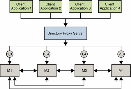
Directory Proxy Server can also be used to protect a replicated directory service from failure due to a faulty client application. To improve availability, a limited set of masters or replicas is assigned to each application.
Suppose a faulty application causes a server shutdown when the application performs a specific action. If the application fails over to each successive replica, a single problem with one application can result in failure of the entire replicated topology. To avoid such a scenario, you can restrict failover and load balancing of each application to a limited number of replicas. The potential failure is then limited to this set of replicas, and the impact of the failure on other applications is reduced.
Sample Topologies Using Redundancy for High Availability
The following sample topologies show how redundancy is used to provide continued service in the event of failure.
Using Replication for Availability in a Single Data Center
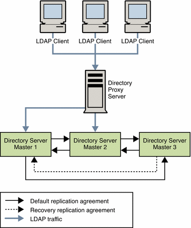
The data center that is illustrated in the following figure has a multi-master topology with three masters. In this scenario, the third master is used only for availability in thdse event of failure. Read and write operations are routed to Masters 1 and 2 by Directory Proxy Server, unless a problem occurs. To speed up recovery and to minimize the number of replication agreements, recovery replication agreements are created. These agreements are disabled by default but can be enabled rapidly in the event of a failure.
Figure 12–1 Multi-Master Replication in a Single Data Center
Single Data Center Failure Matrix
In the scenario depicted in Figure 12–1, various components might become unavailable. These potential points of failure and the related recovery actions are described in this table.
Table 12–1 Single Data Center Failure Matrix|
Failed Component |
Action |
|---|---|
|
Master 1 |
Read and write operations are rerouted to Masters 2 and 3 through Directory Proxy Server while Master 1 is repaired. The recovery replication agreement between Master 2 and Master 3 is enabled so that updates to Master 3 are replicated to Master 2. |
|
Master 2 |
Read and write operations are rerouted to Masters 1 and 3 while Master 2 is repaired. The recovery replication agreement between Master 1 and Master 3 is enabled so that updates to Master 3 are replicated to Master 1. |
|
Master 3 |
Because Master 3 is a backup server only, the directory service is not affected if this master fails. Master 3 can be taken offline and repaired without interruption to service. |
|
Directory Proxy Server |
Failure of Directory Proxy Server results in severe service interruption. A redundant instance of Directory Proxy Server is advisable in this topology. For an example of such a topology, see Using Multiple Directory Proxy Servers. |
Single Data Center Recovery Procedure
In a single data center with three masters, read and write capability is maintained if one master fails. This section describes a sample recovery strategy that can be applied to reinstate the failed component.
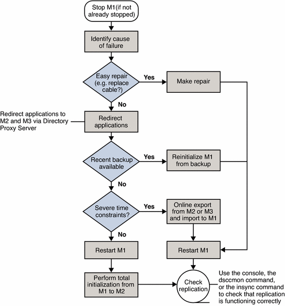
The following flowchart and procedure assume that one component, Master 1, has failed. If two masters fail simultaneously, read and write operations must be routed to the remaining master while the problems are fixed.
Figure 12–2 Single Data Center Sample Recovery Procedure
 To Recover on Failure of One Component
-
If Master 1 is not already stopped, stop it.
-
Identify the cause of the failure.
-
If the failure is easily repaired, by replacing a network cable, for example, make the repair and go to Step 3.
-
If the problem is more serious, the failure might take more time to fix.
-
Ensure that any applications that access Master 1 are redirected to point to Master 2 or Master 3, through Directory Proxy Server.
-
Check the availability of a recent backup.
-
If a recent backup is available, reinitialize Master 1 from the backup and go to Step 3.
-
If a recent backup is not available, do one of the following:
-
Restart Master 1 and perform a total initialization from Master 2 or from Master 3 to Master 1.
For details on this procedure, see Initializing Replicas in Sun Java System Directory Server Enterprise Edition 6.0 Administration Guide.
-
If performing a total initialization will take too long, perform an online export from Master 2, or Master 3, and an import to Master 1.
-
-
-
-
Start Master 1, if it is not already started.
-
If Master 1 is in read-only mode, set it to read/write mode.
-
Check that replication is functioning correctly.
You can use DSCC, dsccmon view-suffixes, or the insync command to check replication.
For more information, see Getting Replication Status in Sun Java System Directory Server Enterprise Edition 6.0 Administration Guide, dsccmon(1M), and insync(1).
Using Replication for Availability Across Two Data Centers
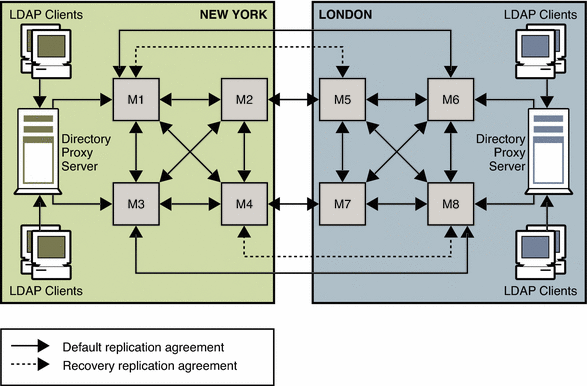
Generally in a deployment with two data centers, the same recovery strategy can be applied as described for a single data center. If one or more masters become unavailable, Directory Proxy Server automatically reroutes local reads and writes to the remaining masters.
As in the single data center scenario described previously, recovery replication agreements can be enabled. These agreements ensure that both data centers continue to receive replicated updates in the event of failure. This recovery strategy is illustrated in Figure 12–3.
An alternative to using recovery replication agreements is to use a fully meshed topology in which every master replicates its changes to every other master. While fewer replication agreements might be easier to manage, no technical reason exists for not using a fully meshed topology.
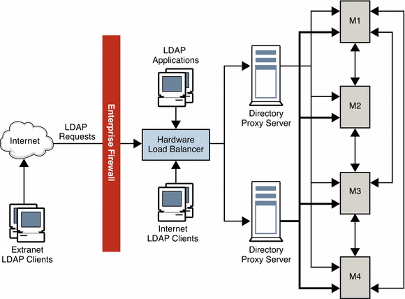
The only SPOF in this scenario would be the Directory Proxy Server in each data center. Redundant Directory Proxy Servers can be deployed to eliminate this problem, as shown in Figure 12–4.
Figure 12–3 Recovery Replication Agreements For Two Data Centers
The recovery strategy depends on which combination of components fails. However, after you have a basic strategy in place to cope with multiple failures, you can apply that strategy if other components fail.
In the sample topology depicted in Figure 12–3, assume that Master 1 and Master 3 in the New York data center fail.
In this scenario, Directory Proxy Server automatically reroutes reads and writes in the New York data center to Master 2 and Master 4. This ensures that local read and write capability is maintained at the New York site.
Using Multiple Directory Proxy Servers
The deployment shown in the following figure includes an enterprise firewall that rejects outside access to internal LDAP services. Client LDAP requests that are initiated internally go through Directory Proxy Server by way of a network load balancer, ensuring high availability at the IP level. Direct access to the Directory Servers is prevented, except for the host that is running Directory Proxy Server. Two Directory Proxy Servers are deployed to prevent the proxy from becoming an SPOF.
A fully meshed multi-master topology ensures that all masters can be used at any time in the event of failure of any other master. For simplicity, not all replication agreements are shown in this diagram.
Figure 12–4 Internal High Availability Configuration
Using Application Isolation
In the scenario illustrated in the following figure a bug in Application 1 causes Directory Server to fail. The proxy configuration ensures that LDAP requests from Application 1 are only ever sent to Master 1 and to Master 3. When the bug occurs, Masters 1 and 3 fail. However, Applications 2, 3, and 4 are not disabled, because they can still reach a functioning Directory Server.
Figure 12–5 Using Application Isolation in a Scaled Deployment
Using Clustering for High Availability
From a physical perspective, a cluster consists of between one and eight servers that work together as a single entity. The servers work together to provide highly available access to applications, system resources, and data. Each server can be a symmetric multiprocessor with multiple CPUs.
A clustering solution can provide high availability for the following:
-
Servers and software
-
Storage subsystem
-
Network adaptor
Clustering does not mitigate all SPOFs in a directory architecture. Failures in the external network, power generation, and data center must be mitigated outside of a clustering solution.
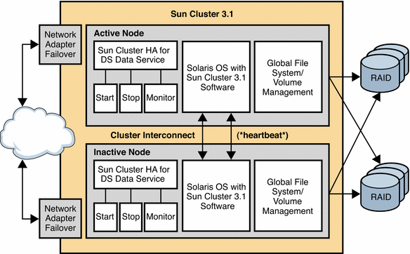
Currently the only supported clustering technology for Directory Server is Sun Cluster 3.1. Using Sun Cluster 3.1 for directory service availability involves installing and configuring the Sun Cluster HA for Directory Server data service as a failover data service. This strategy allows Directory Server to fail over safely in a Sun Cluster 3.1 environment.
The following figure shows the position of the Sun Cluster HA for Directory Server data service in the Sun Cluster 3.1 architecture.
Figure 12–6 Sun Cluster 3.1 Architecture
Hardware Redundancy
The architecture of a Sun Cluster hardware system is designed so that no SPOF can make a cluster unavailable. Redundant high-speed interconnects, storage system connections, and public networks ensure that cluster connectivity does not experience single failures.
Clients connect to the cluster through public network interfaces. If a network adapter card has multiple hardware interfaces, the card can connect to one or more public networks. You can set up nodes to include multiple network interface cards. The cards are configured so that one card is active, and the other cards operate as backups.
A cluster file system is a proxy between the kernel on one or more nodes and the underlying file system and volume manager. The cluster file system runs on a node that has a physical connection to the disks. For a cluster file system to be highly available, you must attach the disks to multiple nodes. A local file system that is made into a cluster file system is not highly available. A local file system implies a file system that is stored on a node's local disk.
A volume manager provides for mirrored or RAID 5 configurations for data redundancy of multihost disks. You can combine multihost disks with disk mirroring and striping to protect against both node failure and individual disk failure.
The cluster interconnect is a private network that transfers cluster-private communications and data service communications between cluster nodes. Redundant NICs, junctions, and cables protect against network failure.
Monitoring in a Clustered Solution
The cluster continuously monitors all its members. It blocks failed nodes from participating in the cluster, which prevents any exchange of corrupt data. The cluster also monitors applications, and it fails over or restarts the applications in case of failures.
Public Network Management, a subsystem of the Sun Cluster software, monitors the active interface. If the active adapter fails, Network Adapter Failover software is called to fail over the interface to one of the backup adapters.
The Cluster Membership Monitor (CMM) is a distributed set of agents, with one set per cluster member or node. The agents exchange messages over the cluster interconnect to ensure full connectivity among all nodes. When the CMM detects a change in cluster membership because of a node failure, for example, the CMM reconfigures the cluster. If the CMM detects a critical problem with a node, the CMM contacts the cluster framework. The cluster framework then forcibly shuts down the node and removes it from the cluster membership.
System Maintenance
You can minimize planned downtime for system maintenance by moving data and applications from the component that needs maintenance to another component on the system. When the maintenance is complete, you can move the data and applications back to the original component.
Directory Server Failover Data Service
The Directory Server Failover Data Service runs on a single node in a cluster. However, nodes can have multiple CPUs for scalability. A fault monitor periodically monitors this failover service.
The Resource Group Manager (RGM) manages data services as resources. When a CMM changes a cluster's membership, the RGM might request changes to the cluster's online or offline resources. The RGM starts and stops failover data services.
Disaster Recovery
The following sections describe how a service is recovered if the Directory Server Data Service fails and if the server fails.
Recovery in the Event of Application Failure
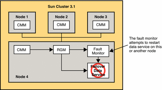
If the fault monitor determines that the Directory Server Data Service has failed, the monitor initiates action to restart the service. The action that is taken depends on the service's configuration.
You can configure the failover data service to attempt to restart a failed service on the same node. Alternatively, the data service can be configured to immediately start a failed service on a different node. If the data service is configured to attempt to restart on the same node, the fault monitor contacts the local RGM. The local RGM then attempts to restart the failed service. If this action fails, the local RGM attempts to start the service on a different node.
If a failed data service cannot be restarted on the same node, the local node's RGM attempts to locate a version of the service on another node. This action also occurs if the data service is configured to start on a different node after failure. If the local RGM finds a version of the service, the local RGM contacts the local CMM and requests that it contact the remote node over the cluster interconnect. The remote CMM then contacts the local RGM and directs it to start the service.
The following figure illustrates recovery in the event of application failure.
Figure 12–7 Application Failure and Recovery in a Sun Cluster 3.1 Architecture
Recovery in the Event of Server Failure
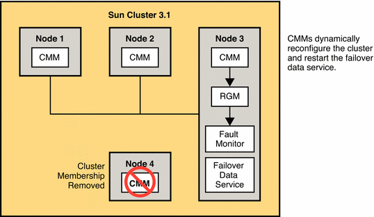
If the server or node on which the Directory Server Data Service is running fails, the service is migrated to another working node. No user intervention is required. This service uses a failover resource group, a container that defines the Directory Server instances, and hosts that support the failover requirements.
The following figure illustrates recovery in the event of server failure.
Figure 12–8 Server Failure and Recovery in a Sun Cluster 3.1 Architecture
- © 2010, Oracle Corporation and/or its affiliates
