Storage Array Cabling Configurations
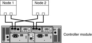
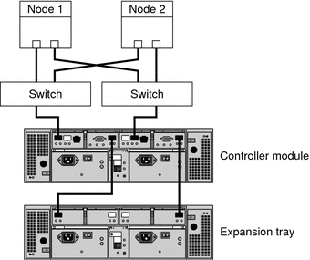
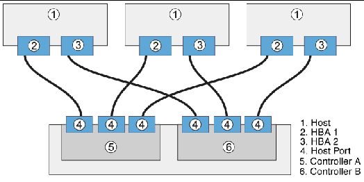
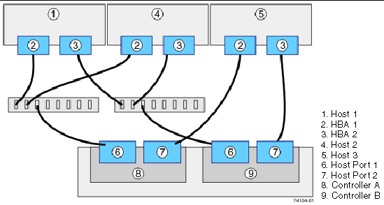
You can install your storage array in several different configurations; see Figure 2–1 through Figure 2–4 for examples.
Figure 2–1 StorageTek Array Direct-Connect Configuration

The StorageTek 6140 array houses two controllers; each controller has four host ports. The cabling approach is the same as shown in Figure 2–1, but it can support up to four nodes in a direct-attach configuration.
Figure 2–2 StorageTek Array Switched Configuration

Figure 2–2 shows a switched configuration for a two-node storage array.
Figure 2–3 Direct Connections from Three Data Hosts with Dual HBAs

You can connect one or more hosts to a storage array. Figure 2–3 shows an example of a direct host connection from each data host with dual HBAs.
Note –
For maximum hardware redundancy, you should install a minimum of two HBAs in each host and distribute I/O paths between these HBAs. A single, dual-port HBA can provide both data paths to the storage array but does not ensure redundancy if the HBA fails.
Figure 2–4 Mixed Topology-Three Hosts Connected Through a Switch or Connected Directly

Figure 2–4 shows that three hosts can be connected directly or through a switch.
- © 2010, Oracle Corporation and/or its affiliates
