Chapter 2 Installing and Configuring a StorageTek Array
This chapter contains the procedures about how to install and configure StorageTek RAID arrays. These procedures are specific to a SunTM Cluster environment.
This chapter contains the following main topics:
For detailed information about storage array architecture, features, configuration utilities, and installation, see Related Documentation.
Installing Storage Arrays
This section contains the procedures listed in Table 2–1.
Table 2–1 Task Map: Installing Storage Arrays|
Task |
Information |
|---|---|
|
Install a storage array in a new cluster, before the OS and Sun Cluster software are installed. | |
|
Add a storage array to an existing cluster. |
Storage Array Cabling Configurations
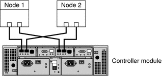
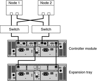
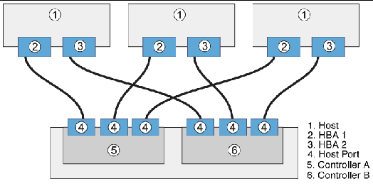
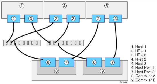
You can install your storage array in several different configurations; see Figure 2–1 through Figure 2–4 for examples.
Figure 2–1 StorageTek Array Direct-Connect Configuration

The StorageTek 6140 array houses two controllers; each controller has four host ports. The cabling approach is the same as shown in Figure 2–1, but it can support up to four nodes in a direct-attach configuration.
Figure 2–2 StorageTek Array Switched Configuration

Figure 2–2 shows a switched configuration for a two-node storage array.
Figure 2–3 Direct Connections from Three Data Hosts with Dual HBAs

You can connect one or more hosts to a storage array. Figure 2–3 shows an example of a direct host connection from each data host with dual HBAs.
Note –
For maximum hardware redundancy, you should install a minimum of two HBAs in each host and distribute I/O paths between these HBAs. A single, dual-port HBA can provide both data paths to the storage array but does not ensure redundancy if the HBA fails.
Figure 2–4 Mixed Topology-Three Hosts Connected Through a Switch or Connected Directly

Figure 2–4 shows that three hosts can be connected directly or through a switch.
How to Install Storage Arrays in a New Cluster
Use this procedure to install a storage array in a new cluster. To add a storage array to an existing cluster, use the procedure in How to Replace a Host Adapter in Sun Cluster 3.1 - 3.2 With Sun StorEdge A3500FC System Manual for Solaris OS.
This procedure relies on the following assumptions:
-
You have not installed the Solaris Operating System.
-
You have not installed the Sun Cluster software.
-
You have enough host adapters to connect the nodes and the storage array.
 Install and Cable the Hardware
-
Unpack, place, and level the storage array.
For instructions, see the StorageTek online documentation.
-
If necessary, install the Fibre Channel (FC) switch for the storage array (if the switch is not already installed).
For the procedure about how to install an FC switch, see the documentation that shipped with your FC switch hardware.
-
Connect the nodes to the storage array.
-
SAN Configuration — Connect the FC switches to the storage array
-
Direct-Attached Configuration — Connect each node directly to the storage array
-
SAS Direct-Attached Configuration
-
iSCSI Direct-Attached Configuration
-
iSCSI Switched Configuration
For instructions, see your storage array documentation and the Related Documentation section.
-
-
Hook up the cards for the storage array.
For instructions, see your storage array documentation.
-
Power on the storage array and the nodes.
For instructions, see your storage array documentation.
-
Configure the storage array, if needed.
For instructions, see Configuring Storage Arrays and consult your storage array documentation.
 Install the Solaris Operating
System and Configure Multipathing
-
On all nodes, install the Solaris operating system and apply the required Solaris patches for Sun Cluster software and storage array support.
For the procedure about how to install the Solaris operating environment, see How to Install Solaris Software in Sun Cluster Software Installation Guide for Solaris OS.
-
Install any required patches or software for Solaris I/O multipathing software support to nodes and enable multipathing.
For the procedure about how to install the Solaris I/O multipathing software, see How to Install Sun Multipathing Software in Sun Cluster Software Installation Guide for Solaris OS.
See Also
-
To create a logical volume, see How to Create a Logical Volume.
-
To continue with Sun Cluster software installation tasks, see your Sun Cluster software installation documentation.
 How to Add Storage Arrays
to an Existing Cluster
Use this procedure to add a new storage array to a running cluster. To install a new storage array in a Sun Cluster configuration that is not running (the nodes are in noncluster mode), use the procedure in How to Install Storage Arrays in a New Cluster.
Before You Begin
This procedure relies on the following assumptions:
-
(Veritas Volume Manager Only) You have a version of Veritas Volume Manager that includes Array Support Library (ASL).
-
You have enough host adapters to connect the nodes and the storage array.
If you need to install host adapters, see How to Replace a Host Adapter in Sun Cluster 3.1 - 3.2 With Sun StorEdge A3500FC System Manual for Solaris OS. When this procedure asks you to replace the failed host adapter, install the new host adapter instead.
-
All cluster nodes have joined the cluster.
If you need to add a node to your cluster, see your Sun Cluster system administration documentation. Ensure that you install the required Solaris patches for storage array support.
-
Unpack, place, and level the storage array.
For instructions, see the StorageTek online documentation.
-
If necessary, install the Fibre Channel (FC) switch for the storage array (if the switch is not already installed).
For the procedure about how to install an FC switch, see the documentation that shipped with your FC switch hardware.
-
Connect the nodes to the storage array.
-
SAN Configuration — Connect the FC switches to the storage array
-
Direct-Attached Configuration — Connect each node directly to the storage array
-
SAS Direct-Attached Configuration
-
iSCSI Direct-Attached Configuration
-
iSCSI Switched Configuration
For instructions, see your storage array documentation and the Related Documentation section.
-
-
Hook up the cards for the storage array.
For instructions, see your storage array documentation.
-
Power on the storage array and the nodes.
For instructions, see your storage array documentation.
-
Configure the storage array, if needed.
For instructions, see Configuring Storage Arrays and consult your storage array documentation.
See Also
-
To create a logical volume, see How to Create a Logical Volume.
Configuring Storage Arrays
This section contains the procedures to configure a storage array in a running cluster. Table 2–2 lists these procedures.
Table 2–2 Task Map: Configuring a Storage Array|
Task |
Information |
|---|---|
|
Create a logical volume | |
|
Remove a logical volume |
The following is a list of administrative tasks that do not require cluster-specific procedures. See the storage array's documentationRelated Documentation for the following procedures.
 How to Create
a Logical Volume
Use this procedure to create a logical volume from unassigned storage capacity.
Note –
Sun storage documentation uses the following terms:
-
Logical volume
-
Logical device
-
Logical unit number (LUN)
This manual uses logical volume to refer to all such logical constructs.
Before You Begin
This procedure relies on the following prerequisites and assumptions.
-
All nodes are booted in cluster mode and attached to the storage device.
-
The storage device is installed and configured. If you are using multipathing, the storage device is configured as described in the installation procedure.
-
If you are using Solaris I/O multipathing (MPxIO) for the Solaris 10 OS, previously called Sun StorEdge Traffic Manager in the Solaris 9 OS, verify that it is installed and configured and the path to the storage device is functioning. To configure the Traffic Manager for the Solaris 9 OS, see the Sun StorEdge Traffic Manager Installation and Configuration Guide. To configure multipathing for the Solaris 10 OS, see the Solaris Fibre Channel Storage Configuration and Multipathing Support Guide.
This procedure provides the long forms of the Sun Cluster commands. Most commands also have short forms. Except for the forms of the command names, the commands are identical. For a list of the commands and their short forms, see Appendix A, Sun Cluster Object-Oriented Commands, in Sun Cluster 3.1 - 3.2 Hardware Administration Manual for Solaris OS.
-
Become superuser or assume a role that provides solaris.cluster.modify role-based access control (RBAC) authorization.
-
Follow the instructions in your storage device's documentation to create and map the logical volume. For a URL to this storage documentation, see Related Documentation.
-
Completely set up the logical volume. When you are finished, the volume must be created, mapped, mounted, and initialized.
-
If necessary, partition the volume.
-
To allow multiple clusters and nonclustered nodes to access the storage device, create initiator groups by using LUN masking.
-
-
If you are not using multipathing, skip to Step 5.
-
If you are using multipathing, and if any devices that are associated with the volume you created are at an unconfigured state, configure the multipathing paths on each node that is connected to the storage device.
To determine whether any devices that are associated with the volume you created are at an unconfigured state, use the following command.
# cfgadm -al | grep disk
Note –To configure the Solaris I/O multipathing paths on each node that is connected to the storage device, use the following command.
# cfgadm -o force_update -c configure controllerinstance
To configure the Traffic Manager for the Solaris 9 OS, see the Sun StorEdge Traffic Manager Installation and Configuration Guide. To configure multipathing for the Solaris 10 OS, see the Solaris Fibre Channel Storage Configuration and Multipathing Support Guide.
-
On one node that is connected to the storage device, use the format command to label the new logical volume.
-
From any node in the cluster, update the global device namespace.
-
If you are using Sun Cluster 3.2, use the following command:
# cldevice populate
-
If you are using Sun Cluster 3.1, use the following command:
# scgdevs
Note –You might have a volume management daemon such as vold running on your node, and have a DVD drive connected to the node. Under these conditions, a device busy error might be returned even if no disk is inserted in the drive. This error is expected behavior. You can safely ignore this error message.
-
-
To manage this volume with volume management software, use Solaris Volume Manager or Veritas Volume Manager commands to update the list of devices on all nodes that are attached to the new volume that you created.
For more information, see your Solaris Volume Manager or Veritas Volume Manager documentation.
See Also
-
To configure a logical volume as a quorum device, see Chapter 6, Administering Quorum, in Sun Cluster System Administration Guide for Solaris OS.
-
To create a new resource or configure a running resource to use the new logical volume, see Chapter 2, Administering Data Service Resources, in Sun Cluster Data Services Planning and Administration Guide for Solaris OS.
 How to Remove a
Logical Volume
Use this procedure to remove a logical volume. This procedure defines Node A as the node with which you begin working.
Note –
Sun storage documentation uses the following terms:
-
Logical volume
-
Logical device
-
Logical unit number (LUN)
This manual uses logical volume to refer to all such logical constructs.
Before You Begin
This procedure relies on the following prerequisites and assumptions.
-
All nodes are booted in cluster mode and attached to the storage device.
-
The logical volume and the path between the nodes and the storage device are both operational.
This procedure provides the long forms of the Sun Cluster commands. Most commands also have short forms. Except for the forms of the command names, the commands are identical. For a list of the commands and their short forms, see Appendix A, Sun Cluster Object-Oriented Commands, in Sun Cluster 3.1 - 3.2 Hardware Administration Manual for Solaris OS.
-
Become superuser or assume a role that provides solaris.cluster.read and solaris.cluster.modify RBAC authorization.
-
Identify the logical volume that you are removing.
Refer to your Solaris Volume Manager or Veritas Volume Manager documentation for more information.
-
(Optional) Migrate all data off the logical volume that you are removing. Alternatively, back up that data.
-
If the LUN that you are removing is configured as a quorum device, choose and configure another device as the quorum device. Then remove the old quorum device.
To determine whether the LUN is configured as a quorum device, use one of the following commands.
-
If you are using Sun Cluster 3.2, use the following command:
# clquorum show
-
If you are using Sun Cluster 3.1, use the following command:
# scstat -q
For procedures about how to add and remove quorum devices, see Chapter 6, Administering Quorum, in Sun Cluster System Administration Guide for Solaris OS.
-
-
If you are using volume management software, use that software to update the list of devices on all nodes that are attached to the logical volume that you are removing.
For instructions about how to update the list of devices, see your Solaris Volume Manager or Veritas Volume Manager documentation.
-
If you are using volume management software, run the appropriate Solaris Volume Manager or Veritas Volume Manager commands to remove the logical volume from any diskset or disk group.
For more information, see your Solaris Volume Manager or Veritas Volume Manager documentation.
Note –Volumes that were managed by Veritas Volume Manager must be completely removed from Veritas Volume Manager control before you can delete them from the Sun Cluster environment. After you delete the volume from any disk group, use the following commands on both nodes to remove the volume from Veritas Volume Manager control.
# vxdisk offline Accessname
# vxdisk rm Accessname
- Accessname
-
Disk access name
-
If you are using multipathing, unconfigure the volume in Solaris I/O multipathing.
# cfgadm -o force_update -c unconfigure Logical_Volume
-
Access the storage device and remove the logical volume.
To remove the volume, see your storage documentation. For a list of storage documentation, see Related Documentation.
-
Determine the resource groups and device groups that are running on all nodes.
Record this information because you use it in Step 14 and Step 15 of this procedure to return resource groups and device groups to these nodes.
-
Move all resource groups and device groups off Node A.
-
Shut down and reboot Node A.
To shut down and boot a node, see Chapter 3, Shutting Down and Booting a Cluster, in Sun Cluster System Administration Guide for Solaris OS.
-
On Node A, remove the paths to the logical volume that you removed. Remove obsolete device IDs.
-
For each additional node that is connected to the shared storage that hosted the logical volume, repeat Step 9 to Step 12.
-
(Optional) Restore the device groups to the original node.
Do the following for each device group that you want to return to the original node.
-
If you are using Sun Cluster 3.2, use the following command:
# cldevicegroup switch -n nodename devicegroup1[ devicegroup2 …]
- -n nodename
-
The node to which you are restoring device groups.
- devicegroup1[ devicegroup2 …]
-
The device group or groups that you are restoring to the node.
-
If you are using Sun Cluster 3.1, use the following command:
# scswitch -z -D devicegroup -h nodename
-
-
(Optional) Restore the resource groups to the original node.
Do the following for each resource group that you want to return to the original node.
-
If you are using Sun Cluster 3.2, use the following command:
# clresourcegroup switch -n nodename resourcegroup1[ resourcegroup2 …]
- nodename
-
For failover resource groups, the node to which the groups are returned. For scalable resource groups, the node list to which the groups are returned.
- resourcegroup1[ resourcegroup2 …]
-
The resource group or groups that you are returning to the node or nodes.
-
If you are using Sun Cluster 3.1, use the following command:
# scswitch -z -g resourcegroup -h nodename
-
- © 2010, Oracle Corporation and/or its affiliates
