JavaScript is required to for searching.
Skip Navigation Links
Exit Print View
SPARC Enterprise T5120 and T5220 Servers Topic Set
search filter icon
search icon

Document Information

Using This Documentation

Related Documentation

Documentation, Support, and Training

Documentation Feedback

Site Planning

Sun SPARC Enterprise T5120 and T5220 Servers Site Planning Guide

Physical Specifications

Minimum Clearance for Service Access

Environmental Specifications

Power Source Requirements

Acoustic Noise Emissions

Agency Compliance Specifications

Operating Environment Requirements

SPARC: Electrical Power

Ambient Temperature

Ambient Relative Humidity

Airflow Considerations

Installation

Preparing for Installation

Server Overview

Server Handling Precautions

Input Power Information and Precautions

Tools and Equipment Needed

Optional Component Installation

ESD Precautions

Installation Overview

Preparing for Installation

Installing the Hardware

Configuring the Service Processor

Configuring the Host Software

Cabling Notes for Both Servers

Port, Connector, and LED Locations for Both Servers

Slide Rail Assembly Notes for Both Servers

Cable Management Notes for Both Servers

Installing the SPARC Enterprise T5120 and T5220 Servers

Installing the Servers in a Rack

Installing the Cable Management Arm for Both Servers

Connecting the Server Cables for Both Servers

Managing Cables With the CMA

Dismounting the Servers

Powering On the System

Powering On the System for the First Time

Enabling the Service Processor Network Management Port

Logging Into the Service Processor

Using the Service Processor for Common Operations

Power On the System

Connect to the System Console

Perform a Normal System Initialization

Devices in the OpenBoot Device Tree

Boot the Solaris Operating System

Avoid Booting the Solaris Operating System at Startup

Reset the System

Power Cycle the System

Verifying System Functionality

Updating the Firmware

flashupdate command

Update the Firmware

Selecting a Boot Device

Selecting a Boot Device

Installing the Servers With the Express Rail Rackmounting Kit

Slide Rail Assembly Notes for the Express Rail Rackmounting Kit

Installing the Servers in a Rack With Express Rails

Installing the Cable Management Arm

Dismounting the Server

Assembling and Installing DC Power Cables for the Sun SPARC Enterprise T5120 Server

Requirements for Servers With DC Input Power

DC Supply and Ground Conductor Requirements

Overcurrent Protection Requirements

Assembling and Installing the DC Input Power Cables

Connecting the DC Input Power Cords to the Server

Assembling and Installing DC Power Cables for the Sun SPARC Enterprise T5220 Server

Requirements for Servers With DC Input Power

Assembling and Installing the DC Input Power Cables

Administration

Communicating With the System

ILOM Overview

Log In to ILOM

Log In to the System Console

Display the ok Prompt

Display the ILOM ->Prompt

Use a Local Graphics Monitor

Performing Common Tasks

Power On the System

Power Off the System

Reset the System

Update the Firmware

Managing Disks

Hardware RAID Support

Creating Hardware RAID Volumes

Delete a Hardware RAID Volume

Hot-Plug a Mirrored Disk

Hot-Plug a Nonmirrored Disk

Disk Slot Numbers

Managing Devices

Unconfigure a Device Manually

Reconfigure a Device Manually

Devices and Device Identifiers

Sun SPARC Enterprise T5x20 Device Tree

Multipathing Software

Handling Faults

Discovering Faults

Bypassing Minor Faults

Clear a Fault

Managing Logical Domains Software

Logical Domains Software Overview

Logical Domain Configurations

View OpenBoot Configuration Variables

OpenBoot Configuration Variables on the SCC

Remote Management (ILOM 3.0)

Understanding ILOM 3.0 for the Sun SPARC Enterprise T5120 and T5220 Servers

ILOM Overview

Platform-Specific ILOM Features

ILOM Features Not Supported

Managing the Host

Reset the Host

Managing Host Boot Mode

Viewing and Configuring Host Control Information

Managing System User Interactions

Managing the Service Processor

Storing Customer Information

Display Console History (CLI)

Change Console Escape Characters (CLI)

Changing Configuration Policy Settings

Managing Network Access

ILOM Information Stored on the SCC

Managing Devices

Managing Virtual Keyswitch Settings

Discover IPMI Sensors and Indicators

Sensors on Sun SPARC Enterprise T5120 and T5220 Servers

Indicators on Oracle's Sun SPARC Enterprise T5120 and T5220 Servers

Discover ALOM Compatibility Information

ALOM CMT Compatibility Shell

ALOM CMT Variable Comparison

Event Messages Available Through the ALOM Compatibility Shell

Service

Identifying Server Components

SPARC: Infrastructure Boards in Sun SPARC Enterprise T5120 Servers

SPARC: Infrastructure Boards in Sun SPARC Enterprise T5220 Servers

Internal System Cables for Sun SPARC Enterprise T5120 Servers

Internal System Cables for Sun SPARC Enterprise T5220 Servers

Front Panel Controls and Indicators on Sun SPARC Enterprise T5120 Servers

Rear Panel Components and Indicators on Sun SPARC Enterprise T5120 Servers

Front Panel Controls and Indicators on Sun SPARC Enterprise T5220 Servers

Rear Panel Components and Indicators on Sun SPARC Enterprise T5220 Servers

Status LEDs for Ethernet Ports and Network Management Port

Detecting and Managing Faults

Diagnostic Tools Overview

Diagnostics Tools Quick Reference

LED Overview

Detecting Faults With ILOM

ILOM Troubleshooting Overview

Service-Related ILOM Command Summary

Faults Displayed by show faulty

Clear FRU Faults Manually

Display FRU Information With the show Command

Create an ALOM CMT Shell

Detecting Faults With POST

POST Overview

Managing POST Operations

ILOM Properties that Affect POST Behavior

Examples of POST Management

Run POST in Maximum Mode

Clear POST-Detected Faults

POST Output Quick Reference

Managing Faults Using the PSH Feature

Solaris PSH Feature Overview

PSH-Detected Fault Console Message

Identify PSH-Detected Faults With fmdump

Clear PSH-Detected Faults

Viewing Solaris OS Messages

Check the Message Buffer

View the System Message Log Files

Managing Components With Automatic System Recovery Commands

ASR Overview

Display System Components

Disable System Components

Enable System Components

Detecting Faults Using SunVTS Software

Run the SunVTS Software

Preparing to Service the System

General Safety Information

Essential Tools

Find the Chassis Serial Number

Removing Power From the System

Positioning the System for Servicing

Accessing Internal Components

Servicing Hard Drives

Hard Drive Servicing Overview

Hard Drive LEDs

Remove a Hard Drive

Install a Hard Drive

Four-Drive Capable Backplane Configuration Reference

Eight-Drive Capable Backplane Configuration Reference

Sixteen-Drive Capable Backplane Configuration Reference

Servicing Motherboard Components

Servicing FB-DIMMs

Servicing the Air Duct

Servicing PCIe/XAUI Risers

Servicing the Battery

Servicing the SCC Module

Servicing the Motherboard Assembly

Servicing Fan Modules

Fan Module Overview

Remove a Fan Module

Install a Fan Module

Servicing Power Supplies

Power Supplies Overview

Remove a Power Supply

Install a Power Supply

Power Supply Configuration Reference

Servicing Boards and Components

Important Safety Instructions

Servicing DVD/USB Modules

Servicing Fan Power Boards

Servicing the Hard Drive Cage

Servicing the Hard Drive Backplane

Servicing Front Control Panel Light Pipe Assemblies

Servicing Power Distribution Boards

Servicing Power Supply Backplanes (Sun SPARC Enterprise T5220 Servers)

Servicing Paddle Cards

Returning the Server to Operation

Install the Top Cover

Reinstall the Server in the Rack

Return the Server to the Normal Rack Position

Connect Power Cords to the Server

Power On the Server Using the poweron Command

Power On the Server Using the Front Panel Power Button

Identifying FRUs in SPARC Enterprise T5120 Servers

Motherboard Components in T5120 Servers

I/O Components in SPARC Enterprise T5120 Servers

Power Distribution/Fan Module Components in SPARC Enterprise T5120 Servers

Internal Cables for Onboard SAS Controller Cards in SPARC Enterprise T5120 Servers

HDD Data Cable Routing for SAS RAID Controller Cards in Four-Disk Capable SPARC Enterprise T5120 Servers

HDD Data Cable Routing for SAS RAID Controller Cards in Eight-Disk Capable SPARC Enterprise T5120 Servers

Identifying FRUs in Sun SPARC Enterprise T5220 Servers

Motherboard Components in T5220 Servers

I/O Components in Sun SPARC Enterprise T5220 Servers

Power Distribution/Fan Module Components in Sun SPARC Enterprise T5220 Servers

Internal Cables for Onboard SAS Controller Cards in Sun SPARC Enterprise T5220 Servers

HDD Data Cable Routing for SAS RAID Controller Cards in Sun SPARC Enterprise T5220 Servers

Index

Diagnostics Tools Quick Reference

The following flowchart illustrates the complementary relationship of the different diagnostic tools and indicates a default sequence of use.

Figure 55 Diagnostics Flowchart
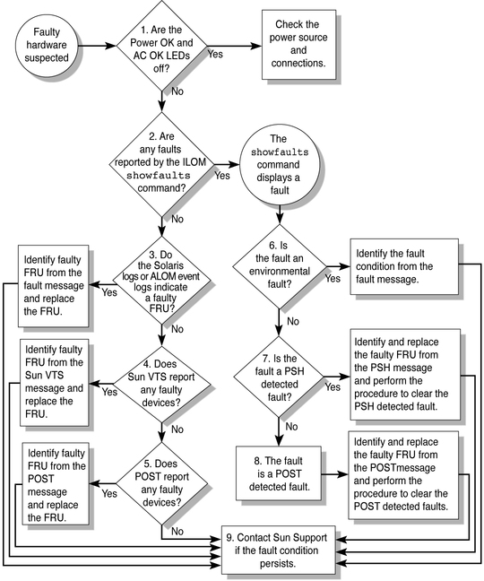
Flow chart showing the diagnostic process.

The following table provides brief descriptions of the troubleshooting actions shown in the flowchart. It also provides links to topics with additional information on each diagnostic action.

Table 38 Diagnostic Flowchart Reference Table

Diagnostic Action
Possible Outcome
Additional Information
Check Power OK and AC Present LEDs on the server.

(Flowchart item 1)

The Power OK LED is located on the front and rear of the chassis.

The AC Present LED is located on the rear of the server on each power supply.

If these LEDs are not on, check the power source and power connections to the server.

Run the ILOM show faulty command to check for faults.

Flowchart item 2)

The show faulty command displays the following kinds of faults:
  • Environmental faults

  • Solaris Predictive Self-Healing (PSH) detected faults

  • POST detected faults

Faulty FRUs are identified in fault messages using the FRU name.

Check the Solaris log files for fault information.

(Flowchart item 3)

The Solaris message buffer and log files record system events, and provide information about faults.
  • If system messages indicate a faulty device, replace the FRU.

  • For more diagnostic information, review the SunVTS report. (Flowchart item 4)

Run SunVTS software.

(Flowchart item 4)

SunVTS is an application you can run to exercise and diagnose FRUs. To run SunVTS, the server must be running the Solaris OS.
  • If SunVTS reports a faulty device, replace the FRU.

  • If SunVTS does not report a faulty device, run POST. (Flowchart item 5)

Run POST.

(Flowchart item 5)

POST performs basic tests of the server components and reports faulty FRUs.
Check if the fault is environmental.

(Flowchart item 6)

Determine if the fault is an environmental fault or a configuration fault.

If the fault listed by the show faulty command displays a temperature or voltage fault, then the fault is an environmental fault. Environmental faults can be caused by faulty FRUs (power supply or fan), or by environmental conditions such as when computer room ambient temperature is too high, or the server airflow is blocked. When the environmental condition is corrected, the fault will automatically clear.

If the fault indicates that a fan or power supply is bad, you can perform a hot-swap of the FRU. You can also use the fault LEDs on the server to identify the faulty FRU (fans and power supplies).

Determine if the fault was detected by PSH.

(Flowchart item 7)

If the fault displayed included a uuid and sunw-msg--id property, the fault was detected by the Solaris Predictive Self-Healing software.

If the fault is a PSH detected fault, refer to the PSH Knowledge Article web site for additional information. The Knowledge Article for the fault is located at the following link:

http://www.sun.com/msg/message-ID

where message-ID is the value of the sunw-msg-id property displayed by the show faulty command.

After the FRU is replaced, perform the procedure to clear PSH detected faults.

Determine if the fault was detected by POST.

(Flowchart item 8)

POST performs basic tests of the server components and reports faulty FRUs. When POST detects a faulty FRU, it logs the fault and if possible, takes the FRU offline. POST detected FRUs display the following text in the fault message:

Forced fail reason

In a POST fault message, reason is the name of the power-on routine that detected the failure.

Contact technical support.

(Flowchart item 9)

The majority of hardware faults are detected by the server’s diagnostics. In rare cases a problem might require additional troubleshooting. If you are unable to determine the cause of the problem, contact your service representative for support.