
This hardware overview is helpful in servicing and maintaining your Desktop Storage Module .
The Desktop Storage Module is an external desktop peripheral that contains the following:
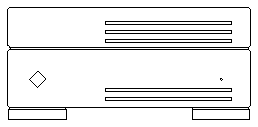
Figures 1-1, 1-2 and 1-3 illustrate front and rear views of the DSM. Figure 1-4 illustrates the top view of a DSM with a disk drive with the cover removed. Figure 1-5 illustrates the top view of a DSM with a tape drive with the cover removed. For simplicity, both Figures 1-4 and 1-5 do not show any cabling.
Figure 1-1 Front View of a Desktop Storage Module with a Disk Drive
Figure 1-2 Front View of a Desktop Storage Module with a Tape Drive
Figure 1-3 Rear View of a Desktop Storage Module
The differences between the disk drive and tape drive versions are the following:
Figure 1-4 Top View of a DSM with a Disk Drive with the Cover Removed
Figure 1-5 Top View of a DSM with a Tape Drive with the Cover Removed
Due to the design of the DSM, you must first remove the disk drive or the tape drive before you can remove the power supply. You need to remove the power supply before you can remove the I/O bracket assembly. However, you do not need to remove the drive to remove and replace the LED harness assembly in the DSM disk drive version.
Figures 1-6 and 1-7 show an exploded view of the disk drive and the tape drive versions. The part numbers in these figures, correct as of the publication date of this document, are subject to change. Consult your authorized Sun sales representative or service provider to confirm part numbers before you order new or replacement parts.
Note that not all of the part numbers are replacement parts. See Appendix B for the replacement parts list.
Exploded View - DSM with a Disk Drive
Exploded View - DSM with a Tape Drive
