Technical Details
The array software consists of a daemon and software objects that run on each of the machines in a Netra Proxy Cache array. On a periodic basis, the array software monitors the health (reachability, load, presence of server processes) of the hardware resources and proxy cache service on each machine. The array software multicasts these individual-host snapshots over an isolated network, called a control network, to which each member of the Netra Proxy Cache array is connected. Netra Proxy Cache Servers are equipped with a second network interface to enable connection to a control network. This second interface is referred to as the control interface.
Note -
The Internet Assigned Numbers Authority (IANA) has designated a multicast address (224.0.1.62) for use with Netra Proxy Cache Array software.
The result of the multicasts over the control network is that all hosts in the array are kept up to date on the health of each host. Responding to these regular updates, array software works to provide users with a continuous proxy cache service, in the face of hardware and software failures and in spite of varying loads on individual servers' resources.
The resource managed by array software is a service address. This is a logical IP address that is associated with the proxy cache service on a given machine. If a machine fails or becomes overloaded, array software can remove the availability of the service address or move the address to a different machine in the array.
A service address is associated with the network interface over which proxy cache server-client interactions occur. In terms of a Netra Proxy Cache array, this is the service interface and the network to which the interface is connected is the service network. The service network is, most often, the local area network (LAN) over which clients access a variety of network services.
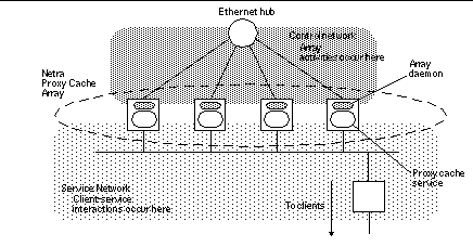
The concepts of control and service networks are illustrated in Figure 1-4.
Figure 1-4 Control and Service Networks

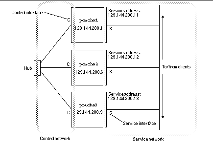
Figure 1-5 illustrates the concepts of control and service interfaces and addresses.
Figure 1-5 Example Netra Proxy Cache Configuration

- © 2010, Oracle Corporation and/or its affiliates
