The Switch Management Agent
The Switch Management Agent (SMA) is a cluster module that maintains communication channels over the private interconnect. SMA monitors the private interconnect and performs a failover of the logical adapter on the surviving private network if it detects a failure. If more than one failure occurs, SMA notifies the Cluster Membership Monitor, which then takes action to change the cluster membership.
Clustered environments have different communication needs depending on the types of data services they support. Clusters providing only HA data services need only heartbeat and minimal cluster configuration traffic over the private interconnect; for these configurations Fast Ethernet is more than adequate. Clusters providing parallel database services send substantial amounts of traffic over the private interconnect. These applications benefit from the increased throughput of SCI.
SMA for SCI Clusters
Scalable Coherent Interface (SCI) is a memory-based high-speed interconnect that enables sharing of memory among cluster nodes. The SCI private interconnect consists of Transmission Control Protocol/Internet Protocol (TCP/IP) network interfaces based on SCI.
Clusters of all sizes may be connected through a switch or hub. However, only two-node clusters may be connected point-to-point. The Switch Management Agent (SMA) software component manages sessions for the SCI links and switches.
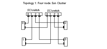
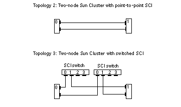
There are three basic SCI topologies supported in Sun Cluster (Figure 1-1 and Figure 1-2):
-
Three- or four-node cluster that requires two SCI switches
-
Two-node cluster connected point-to-point
-
Two-node switched cluster (downgraded case of the four-node cluster that allows for future expansion of cluster nodes, with minimal interruption)
Figure 1-1 SCI Cluster Topology for Four Nodes

Figure 1-2 SCI Cluster Topologies for Two Nodes

SMA for Ethernet Clusters
Clusters of all sizes may be connected through a switch or hub. However, only two-node clusters may be connected point-to-point. The Switch Management Agent (SMA) software component manages communications over the Ethernet switches or hubs.
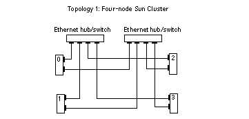
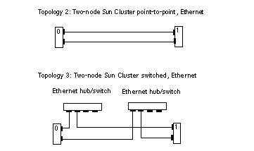
There are three basic Ethernet topologies supported in Sun Cluster (Figure 1-3 and Figure 1-4):
-
Three- or four-node cluster that requires two Ethernet switches or hubs
-
Two-node point-to-point cluster
-
Two-node cluster with Ethernet switches or hubs (a degenerate case of the four-node cluster that allows for future expansion of cluster nodes with minimal interruption)
Figure 1-3 Ethernet Cluster Topology for Four Nodes

Figure 1-4 Ethernet Cluster Topologies for Two Nodes

- © 2010, Oracle Corporation and/or its affiliates
