OTP Topologies
This section provides an overview of the N*N and Pair+N clustered OTP system topologies supported by OTP. A topology is the connection scheme that connects the clustered OTP hosts to the storage platforms used in the cluster.
N*N
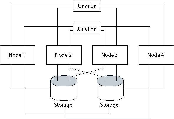
The N*N topology allows every shared storage device in the cluster to connect to every OTP host in the cluster. This topology allows highly available applications to failover from one node to another without service degradation. When failover occurs, the new node can access the storage device using a local path instead of the private interconnect.
The following figure illustrates an N*N configuration where all four OTP hosts connect to shared storage.
Figure 9–1 N*N Topology

The following procedures are supported in N*N topology.
Pair+N
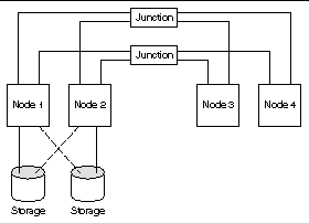
The pair+N topology includes a pair of OTP hosts directly connected to shared storage and an additional set of OTP hosts that use the cluster interconnect to access shared storage. The additional OTP hosts have no direct connection to the shared storage.
The following figure illustrates a pair+N topology where two of the four OTP hosts (Node 3 and Node 4) use the cluster interconnect to access the storage. This configuration can be expanded to include additional OTP hosts that do not have direct access to the shared storage.
Figure 9–2 Pair+N Topology

The following procedures are supported in pair+N topology.
For further information about clustered OTP system topology, see Sun Cluster Concepts Guide for Solaris OS.
- © 2010, Oracle Corporation and/or its affiliates
