Solution Topologies
The following solution topologies are supported:
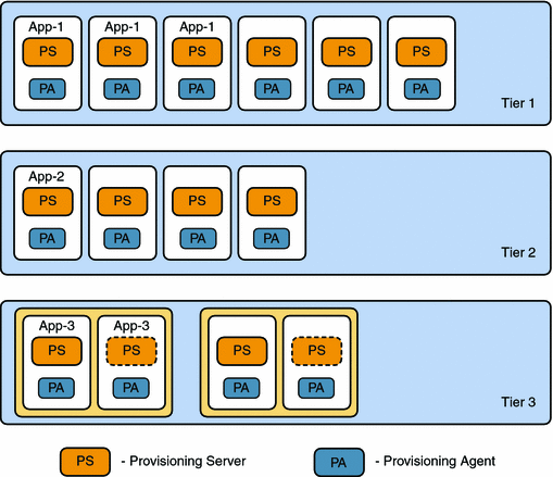
One Provisioning Server for Each Sun OTP Instance
In this topology, one provisioning server is present for each Sun OTP instance.
In tier 3, the provisioning server within the normal box indicates the active node whereas the provisioning server within the dotted line box indicates the failover node or additional node. The figure also shows where you can place your applications in each tier.
Figure 1–1 One Provisioning Server for Each Sun OTP Instance

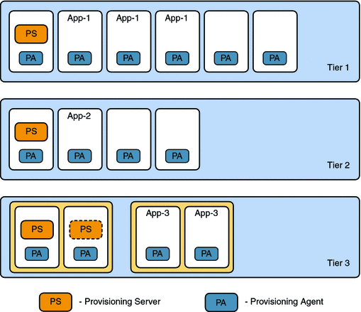
One Provisioning Server for Each Tier
In this topology, one provisioning server is present for each tier.
In tier 3, the provisioning server within the normal box indicates the active node whereas the provisioning server within the dotted line box indicates the failover node or additional node. The figure also shows where you can place your applications in each tier.
In tier 3, the provisioning server is disabled in the second clustered OTP instance.
Figure 1–2 One Provisioning Server for Each Tier

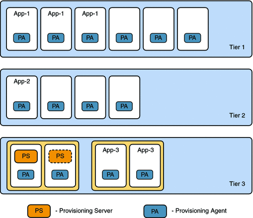
One Provisioning Server for Each Solution Instance
In this topology, one provisioning server is present for the entire solution instance.
In tier 3, the provisioning server within the normal box indicates the active node whereas the provisioning server within the dotted line box indicates the failover node or additional node. The figure also shows where you can place your applications in each tier.
In tier 3, the provisioning server is disabled in the second clustered OTP instance.
Figure 1–3 One Provisioning Server for Each Solution Instance

- © 2010, Oracle Corporation and/or its affiliates
