| Oracle® Communications Service Broker Concepts Guide Release 6.0 Part Number E23524-02 |
|
|
View PDF |
| Oracle® Communications Service Broker Concepts Guide Release 6.0 Part Number E23524-02 |
|
|
View PDF |
This chapter introduces Oracle Communications Service Broker. It provides an overview of the Service Broker features and the different Service Broker solutions.
This chapter also describes the functional architecture of the Service Broker and fundamental concepts of a Service Broker deployment.
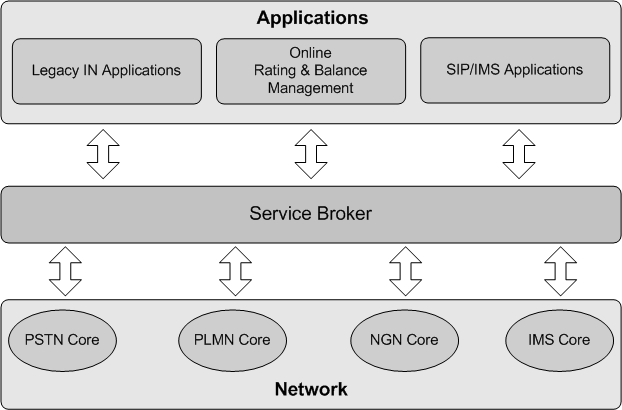
Service Broker enables service delivery for sessions, calls, and events in the network. It controls service delivery across multiple networks, in the legacy and IMS domains, supporting a wide range of protocols, such as SS7-based protocols, SIP, Diameter, RADIUS and more.
Figure 1-1 shows the position of Service Broker in the network.
Service Broker supports a large range of deployment scenarios. The following sections describes the primary functions provided by Service Broker.
Positioned between the application layer and the session control layer, Service Broker controls service delivery for sessions executed in the network, providing protocol mediation and service orchestration.
Using Service Controller, applications such as Service Control Points (SCPs) and SIP application servers, gain access to and control of sessions running in session control layers in different network domains.
For example, the Service Broker NG-IN solution implements stateful mediation between SIP application server and Mobile Switching Centers (MSCs) in the legacy network, providing SIP application servers control of calls executed in the MSC.
Service Controller can also invoke two or more applications, combining and delivering multiple services to sessions in the network. The Service Controller supports mixed orchestration of SIP-based and IN-based applications, supporting orchestration logic which routes a session through a number of applications, invoking the applications in a particular order, according to conditions that determine which application to invoke and in which order.
Using application orchestration, legacy IN applications can work together with new SIP applications, integrating new applications while leveraging existing ones, and enhancing service capabilities. Specifically in legacy networks, this function circumvents IN limitations that allow only one IN application to control a call or a session.
Integrated with the Online Mediation Controller, Service Controller supports mixed orchestration also with Diameter-based charging applications.
Online Mediation Controller provides network connectivity for Oracle Communications Billing and Revenue Management (BRM) and third party Online Charging Systems (OCSs).
Online Mediation Controller acts as the front end for OCSs, providing connectivity to the network and mediating network protocols, supporting the Diameter and RADIUS protocols and enabling delivery of online charging services for sessions in the network.
Online Mediation Controller also extends the OCS functionality traditionally associated with balance management and rating, with additional charging reliant features.
See Oracle Communications Service Broker Online Mediation Controller Implementation Guide for more information.
Policy Controller implements network, subscriber, and service policies, providing control of data usage, quality of service and charging.
Using the Policy Controller you control the service experience of individual subscribers. Policy Controller controls the bandwidth, quality of service, charging, and other service characteristics for each subscriber.
Policy Controller is a fully compliant 3GPP Policy and Charging Rule Function (PCRF), and includes a rule engine that you use to define how resources are allocated among your subscribers. The PCRF makes those decisions based on rules that you set up, information from applications, and subscriber-specific information.
Policy Controller also includes an on-board Subscription Profile Repository (SPR).
Together with the Service Broker Online Mediation Controller and Oracle Communications BRM, Policy Controller provides a complete policy and charging management solution.
See Oracle Communications Service Broker Policy Controller Implementation Guide for more information.
Social Voice Communicator (SVC) is an application that you use to offer subscribers social communications services.
SVC provides a way to connect friends, colleagues, and family with social voice, voicemail, and other features.See Oracle Communications Service Broker SVC Implementation Guide for more information.
Virtual Private Network (VPN) is an application that you use to provide custom voice VPN services to subscribing organizations.
It makes traditional PBX-based VPN feature, such as private extension dialing, calling line identity presentation, and reduced charging rate, available to mobile device users even while away from their home office, city, or country.
VPN allows replacement of IN services running on end-of-life systems. It supports migration from legacy infrastructure and consolidation to IP-based services.
See Oracle Communications Service Broker VPN Implementation Guide for more information.
The Service Broker architecture reflects the Service Broker need to interact with session control entities on one side, and applications on the other side.
On each side, Service Broker interacts through various protocols. Internally, Service Broker performs protocol mediation and optionally service orchestration.
The Service Broker architecture is composed of:
Interworking Modules (IMs)
IMs are a set of interchangeable modules through which Service Broker communicates with applications and session control entities. Each IM provides connectivity to a single application or network entity, through their native protocol.
There are two types of IMs:
Network-facing IMs, connecting Service Broker to session control entities, such as MSCs and Call Session Control Functions (CSCFs). Network-facing IMs provide a stateful front-end to session control entities, thereby entities interact with Service Broker in the same way they interact with application. For a session control entity, connecting to Service Broker is identical to connecting an application. For example, IM-SCF provides a front-end that appears as a standard Service Control Point (SCP) to switches.
Application-facing IMs, connecting Service Broker to applications, such as IN SCPs, SIP ASs, and OCSs. Application-facing IMs provide a stateful front-end to applications, thereby applications interact with Service Broker in the same way they interact with session control entities. For example, IM-OCF provides a front-end that appears as a standard CSCF to OCSs.
While externally IMs communicate with session control entities and applications through a wide range of protocols, inside Service Broker they communicate with the "Orchestration Engine (OE)" through an internal, proprietary, Session Abstraction Layer (SAL) protocol.
The OE resides at the center of the Service Broker architecture. Sessions arriving through IMs, invoke the OE, which routes the sessions through one or more applications based on an orchestration logic that the OE obtains for each session. The OE invokes applications in a specific order, according to conditions that determine which application to invoke and in which order.
Supplementary Modules (SMs)
SMs are interchangeable modules that facilitate and complement Service Broker solutions in certain deployments. The use of SMs is optional.
Applications
Service Broker includes a number of out-of-the-box applications that run in the environment of the Service Broker deployment. When deployed with these services, Service Broker acts as a complete Service Control Point (SCP) and provisioning environment for telecommunication networks.
Applications are available that provide the following services:
Virtual private networking, which provides custom voice VPN services to subscribing organizations. See "Virtual Private Network" for more information.
Social voice communication, which provides end users with social networking communication services such as phone number management, personal contact management, and voicemail. See "Social Voice Communicator" for more information.
Applications are also available in the Online Mediation Controller, that facilitate charging features provided by the OCS.
Mediators
The Online Mediation Controller and Policy Controller include also mediators that bypass the OE and IMs, performing direct mediation between protocols. Those are used when service orchestration is not required.
Inside Service Broker, communication between the OE and IMs is normalized, and communicate is based on the SAL protocol. Each IM provides the conversion between the Service Broker internal SAL representation of the session and the applicable external protocol.
Passing a session through the OE allows Service Broker to apply service orchestration on sessions.
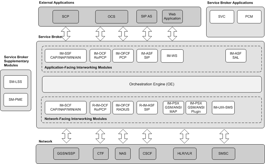
Figure 1-2 shows the full architecture of Service Broker with the Orchestration Engine at the center and a complete set of IMs.
The OE resides at the center of the Service Broker architecture and implements the service orchestration functionality.
The OE takes each session through one or more applications, sequentially, where each application in its turn supplies the service that the application was created for. You specify the applications that the OE invokes, the order in which the OE invokes the applications, and the conditions that determine whether to invoke an application or not, using an orchestration logic.
The OE handles a session as follows:
The OE is invoked, through network-facing IMs, by session control entities. It can be a session control entity in either the legacy domain or the IMS domain.
IM-SCF enables triggering from a legacy domain, and R-IM-ASF SIP and R-IM-OCF Ro enable triggering from an IMS domain.
The OE routes the session sequentially through multiple applications. It uses application-facing IMs to communicate the applications.
Interaction with applications is provided through the following IMs:
IM-SSF to interact with IN SCPs
IM-OCF to interact with OCSs
IM-WS to interact with Web applications
IM-ASF SIP to interact with SIP applications
IM-ASF SAL to interact with Service Broker applications
Routing through multiple applications is not static, but rather determined in real-time based on an orchestration logic, which the OE selects and downloads dynamically. (For more information on how the OE selects and obtains orchestration logic, see "Service Broker Service Orchestration".)
After the session passes the last application in the chain, the OE returns the session back to the session control entity.
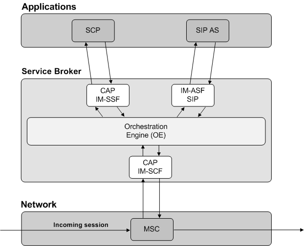
Figure 1-3 shows an example of how the OE routes a session.
Interworking modules are fundamental elements in the Service Broker architecture that allow Service Broker to communicate with the various service platforms and session control platforms in the network.
Each interworking module implements functionality that allows Service Broker to act as a specific network entity towards service platforms and session control platforms, through their native protocole. For example, with IM-SCF, Service Broker acts as an SCP towards SSPs in the network.
IMs normalize the external network interface to a common session and event model interface, the Session Abstraction Layer (SAL) protocols, which is used internally by Service Broker.
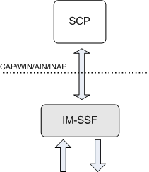
The IM-SSF implements the SSP part of the IN call state model and provides the interface between an IN SCP and Service Broker. From the SCP perspective, Service Broker acts as an MSC/SSP, implementing the Service Switching Function, generating IN triggers, and interacting with the SCP.
Figure 1-4 shows the IN interface between the IM-SSF and SCP, supporting the various IN protocols: CAP, WIN, AIN and INAP.
IM-SSF modules are available for a variety of IN protocols and protocol variants including CAP, AIN, INAP, and WIN.
For example, the IM-SSF CAP supports the complete GSM SSF Call State Model allowing full CAMEL trigger interaction with any CAMEL SCP over CAP protocol.
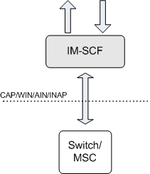
The IM-SCF implements the SCP part of the IN call state model for each IN protocol and variant it handles and provides the interface between the MSC/SSP in the legacy network and Service Broker.
Figure 1-5 shows the IN interface between the IM-SCF and MSC, supporting the various IN protocols: CAP, WIN, AIN and INAP.
For example, the IM-SCF CAP supports the complete CAP Service Control Function (SCF) and IN state model, allowing interaction with any MSC using CAP protocol.
Acting as an SCP, it receives and arms IN triggers from an MSC/SSP and generates internal sessions to Service Broker, based on the trigger information.
IM-SCF modules are available for a variety of IN protocols including CAP, AIN, INAP and WIN.
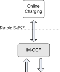
The IM-OCF module implements the mediation module towards any external Diameter-based OCS, acting as 3GPP-compliant Charging Trigger Function (CTF).
Figure 1-6 shows the interface between the IM-OCF and OCS. IM-OCF provides interfaces for the Ro and PCP protocols.
OCS is a telecom platform providing online rating and charging, as well as subscriber balance management. IM-OCF is an application-facing module that communicates with OCS using Diameter Ro, allowing real-time charging for sessions running through Service Broker. With IM-OCF you can implement charging for sessions in any network domain. Another type of IM-OCF supports specific communication with Oracle Communications BRM through PCP.
Deploying IM-OCF with Service Broker's IM-SCF provides a complete online charging solution for SS7-based networks using various IN protocols. Combining IM-OCF with Service Broker's R-IM-ASF SIP provides a complete online charging solution for SIP-based networks, effectively acting as a 3GPP IMS Gateway Function (IMS-GWF).
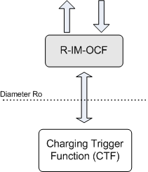
Reverse IM-OCF (R-IM-OCF) is a network-facing IM. It provides an IMS Online Charging Function (OCF) frontend to the network. R-IM-OCF connects Service Broker with IMS core elements that implement 3GPP-compliant Charging Trigger Function (CTF), such as IMS-Gateway Function (IMS-GWF), using the Diameter Credit Control Application interface. It converts charging triggers for online rating and charging to an internal Service Broker representation.
Figure 1-7 shows the Diameter interface between the R-IM-OCF and CTF, supporting Ro.
Deploying R-IM-OCF with Service Broker's IM-SSF provides an online charging solution for IMS-based networks using legacy SS7 IN-based charging, that is SCPs. Deploying R-IM-OCF with Service Broker's IM-OCF provides an online charging solution for IMS-based networks that require mediation towards IMS OCFs. Therefore, R-IM-OCF allows real-time charging for IMS-based sessions using any charging function, whether IN or IMS.
R-IM-OCF allows Service Broker's OE to orchestrate real-time charging requests.
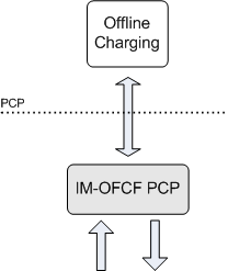
IM-OFCF is an application-facing IM. IM-OFCF enables Service Broker to send accounting requests to, and receive accounting answers, from the Oracle BRM application through the PCP interface. From the perspective of a billing application, IM-OFCF acts as a 3GPP-compliant Charging Trigger Function (CTF).
Figure 1-8 shows the PCP interface between IM-OFCF and the BRM application.
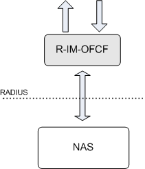
To deploy a complete offline solution, you need to use IM-OFCF PCP with R-IM-OFCF RADIUS. See "R-IM-OFCF RADIUS" for more information.
R-IM-OFCF RADIUS is a network-facing IM. R-IM-OFCF enables Service Broker to receive Accounting-Requests messages from, and send Accounting-Respond messages to, network entities through the Radius interface. From the perspective of a network entity, R-IM-OFCF Radius acts as a 3GPP-compliant Charging Data Function (CDF).
Figure 1-9 shows the Radius interface between R-IM-OFCF and a network entity.
To deploy a complete offline solution, you need to use R-IM-OFCF Radius with IM-OFCF PCP. See "IM-OFCF PCP" for more information.
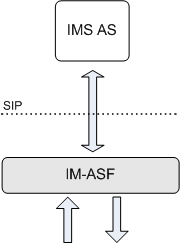
IM-ASF-SIP is an application-facing module connecting Service Broker with SIP applications. Each instance of IM-ASF-SIP provides an interface to one SIP application. You deploy an IM-ASF-SIP instance to add a SIP application to the orchestration sequence, and allow the OE to route sessions through that application.
Figure 1-10 shows the SIP interface between the IM-ASF SIP and application server, supporting SIP.
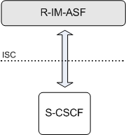
R-IM-ASF SIP is a network-facing module that enables IMS elements, such as Serving Call Session Control Function (S-CSCF), soft switches and Media Gateway Controllers (MGCs), to invoke Service Broker. Each instance of R-IM-ASF SIP provides an interface to one IMS session control entity. You deploy a R-IM-ASF SIP instance to run IMS network sessions run through Service Broker.
Figure 1-11 shows the SIP interface between the R-IM-ASF SIP and S-CSCF, supporting SIP.
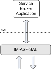
IM-ASF-SAL connects Service Broker with Service Broker applications, that is either out-of-the-box Service Broker applications, such as VPN and SVC, or applications that you implement using the SAL API. Each instance of IM-ASF-SAL provides an internal interface between the OE and one application. You deploy an IM-ASF-SAL instance to add a Service Broker application to the orchestration sequence, and allow the OE to route a session through that application.
Figure 1-12 shows the SAL interface between a Service Broker application and IM-ASF SAL.
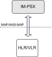
IM-PSX is a network-facing module that enables Service Broker to communicate with HLRs and VLRs in GSM and CDMA networks.
Integrating IM-PSX into Service Broker enables SIP applications to:
Query legacy SS7 networks for information about subscribers, such as state, location, and the services a subscriber owns
Receive notifications from an HLR when a subscriber, who was previously unaccessible, becomes accessible
Modify subscriber information in an SS7 legacy network (in GSM networks only)
Figure 1-13 shows the MAP interface between the IM-PSX and HLR or VLR, supporting GSM MAP and ANSI MAP.
From the HLR's perspective, Service Broker acts as a standard entity in the same network. HLRs can communicate with Service Broker using the MAP protocol (in GSM networks) or ANSI-41 protocol (in CDMA networks). IM-PSX provides interfaces for both MAP and ANSI-41.
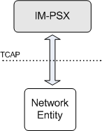
IM-PSX Plugin is a network-facing module that enables Service Broker to handle messages which existing IMs do not support. Unlike other network-facing IMs that communicate with TCAP users (such as CAP, INAP, WIN, or MAP), IM-PSX Plugin communicates with TCAP directly.
Figure 1-14 shows the interface that IM-PSX Plugin provides to receive messages from, and send messages to, an SS7-based network.
IM-PSX Plugin provides interfaces for both ANSI and ETSI networks.
To forward TCAP messages from IM-PSX Plugin to a SIP application, you need to deploy IM-PSX Plugin together with IM-ASF and R-IM-ASF SIP that provide the interface with SIP applications. See "IM-ASF SIP" and "R-IM-ASF SIP" for more information about these modules.
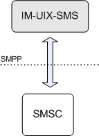
IM-UIX-SMS is a network-facing module that Service Broker use to receive messages from, and send messages to, Short Message Service Centers (SMSCs) through the Short Message Peer-to-Peer Protocol (SMPP).
In conjunction with application-facing IMs (for example, IM-ASF), IM-UIX-SMS provides a solution for routing messages between SMSCs and applications.
Figure 1-15 shows the interface that IM-UIX-SMS provides to receive messages from, and send messages to, SMSCs.
IM-UIX-SMS communicates with SMSCs as follows:
Sending messages from an SMSC to IM-UIX-SMS:
IM-UIX-SMS receives a deliver_sm request sent by an SMSC through the SMPP SSU. IM-UIX-SMS translates the request to a SAL message and sends it to the OE. The OE routes the message to an appropriate IM based on the orchestration logic.
Sending messages from IM-UIX-SMS to an SMSC:
IM-UIX-SMS receives a message from an application, through an application-facing IM supporting the appropriate protocol (for example, through IM-ASF when a message is sent over SIP). Based on this message, IM-UIX-SMS generates a submit_sm message and sends it to an SMSC through the SMPP SSU.
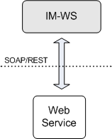
IM-WS is a network-facing module that Service Broker use to receive messages from, and send messages to, web services using Simple Object Access Protocol (SOAP).
Figure 1-16 shows the interface that IM-WS provides to receive messages from, and send messages to, web services.
IM-WS communicates with web services as follows:
Sending messages from IM-WS to a web service:
IM-WS receives an event notification submitted by an application in the SAL format. IM-WS translates this message into a SOAP or REST message and send it to a web service through the WS SSU.
Sending messages from a web service to IM-WS:
IM-WS receives a SOAP message sent by a web service through the WS SSU. IM-WS translates this message from SOAP or REST to a SAL message and sends it to the OE. The OE routes the message to an appropriate IM based on the orchestration logic.
Supplementary Modules (SMs) are optional on-board modules, each facilitating Service Broker solutions in a different manner.
SM-Local Subscriber Server (LSS) is an implementation of a profile server that can be used as a source for service orchestration logic. LSS can store subscriber profiles, including orchestration logic defined in Initial Filter Criteria (iFC) format. When this supplementary module is deployed, the OE can retrieve orchestration logic from the LSS.
SM-Parameter Mapping Engine (PME) is a flexible XML-based engine that manipulates parameters in the headers and body of internal Service Broker SAL messages. SM-PME complements generic solutions with specific requirements and allows fine tuning of parameter mediation for standard and non-standard protocol parameters.
For example, SM-PME can manipulate XER representation of IN messages, allowing CAMEL Furnish Charging Information to update from one format to another Service Broker' OE can chain SM-PME at any point of the service orchestration in the same way that it chains Interworking Modules.
Signaling Server Unit (SSU) is a Service Broker component that enables Service Broker to connect to SS7-based networks and IMS-based networks through standard software and hardware interfaces. There is a specific SSU implementation to support connection to each network domain.
Service Broker includes the following SSUs:
SS7 SSU for TDM, which provides Service Broker with access to a legacy SS7 network through MTP protocols.
SS7 SSU for SIGTRAN, which provides Service Broker with access to a legacy SS7 network through M3UA protocols.
SIP SSU, which provides Service Broker with access to SIP-based networks.
Diameter SSU, which provides Service Broker with access to network entities that interact using the Diameter protocol.
PCP SSU, which provides Service Broker with access to the Oracle BRM application through the Portal Communications Protocol (PCP)
SMPP SSU, which provides Service Broker with access to Short Message System Centers (SMSC) through the Short Message Peer-to-Peer (SMPP) protocol.
Web Services SSU, which enables Service Broker to interact with external entities that use SOAP or REST-based communication.
For more information about SSUs, see "Service Broker Signaling Server Units".
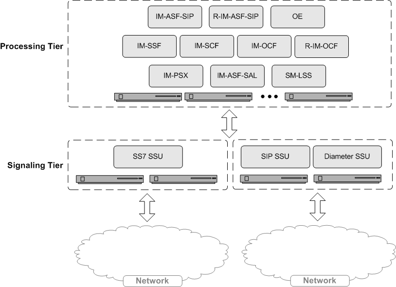
A Service Broker deployment includes two logical tiers as shown in Figure 1-17:
Signaling tier
The signaling tier consists of one or more servers where SSUs run.
Processing tier
The processing tier is a set of servers running functional Service Broker components, that is IMs, OE, SMs, applications and mediators.
Components of the processing tier are stateful. State information is maintained and distributed across the processing tier. Components retrieve and store session state in an in-memory storage. When one server fails, functioning servers continue to retrieve and process all messages, including those stored in the in-memory state of the failing server.
Both signaling and processing tiers are scalable; you can add as many servers as you need to each of the tiers. One exception applies to a signaling tier running TDM SS7 SSUs - in this case you need exactly two servers in the signaling tier.
Normally, a production deployment includes at least four servers, two for each tier, for redundancy purposes.
Service Broker deployments are implemented and administered using domains. To understand the domain-based administration model and how Service Broker is deployed, see the discussion about domains in Oracle Communications Service Broker Installation Guide.
Service Broker is implemented using the Open Services Gateway initiative (OSGi) framework. Service Broker components: IMs, SMs, OE and SSUs, are packaged and deployed as OSGi bundles.
You can install, start, stop, update and uninstall Service Broker bundles without rebooting Signaling Servers and Processing Servers.
The use of OSGi simplifies the Service Broker upgrade procedure and reduces its memory consumption.
For more information about OSGi, see the OSGi Alliance Web site:
Netra 6000 High Availability Manager (HA Manager) is a software module providing management of a complete Service Broker deployment, including hardware and software components.
HA Manager consists of the Service Broker software and an integrated management software operating the hardware and software processes of a Service Broker deployment.
HA Manager is specifically targeted for SUN Netra 6000 hardware, and engineered to work with Oracle Enterprise Linux.
See Oracle Communications Service Broker Netra 6000 High Availability Manager Administrator's Guide for more information.
Service Broker is fully compliant with telecom and other standards. See "Supported Standards" for more information.
|
Copyright © 2010, 2012, Oracle and/or its affiliates. All rights reserved. Legal Notices |
|