| Oracle® Fusion Middleware Application Adapter for PeopleSoft User's Guide for Oracle WebLogic Server 11g Release 1 (11.1.1.4.0) E17055-04 |
|
 Previous |
 Next |
| Oracle® Fusion Middleware Application Adapter for PeopleSoft User's Guide for Oracle WebLogic Server 11g Release 1 (11.1.1.4.0) E17055-04 |
|
 Previous |
 Next |
Oracle Application Adapter for PeopleSoft integrates seamlessly with Oracle Business Process Management (BPM) to facilitate Web service integration. Oracle BPM is based on the Service-Oriented Architecture (SOA). It consumes adapter services exposed as Web Service Definition Language (WSDL) documents.
This chapter contains the following topics:
Designing an Outbound BPM Process Using Transformations for Service Integration
Designing an Inbound BPM Process Using Transformations for Event Integration
To integrate with Oracle BPM, Oracle Application Adapter for PeopleSoft must be deployed in the same WLS container as Oracle BPM. The underlying adapter services must be exposed as WSDL files, which are generated during design time in Oracle Adapter Application Explorer (Application Explorer) for both request-response (outbound) and event notification (inbound) services of the adapter. For more information, see "Generating a WSDL (J2CA Configurations Only)".
The generated WSDL files are used to design the appropriate BPM processes for inbound or outbound adapter services. A completed BPM process must be successfully compiled in JDeveloper and deployed to a BPM server. Upon deployment to the BPM server, every newly built process is automatically deployed to the Oracle Enterprise Manager console, where you run, monitor, and administer BPM processes, and listen to adapter events.
During installation, Oracle Application Adapter for PeopleSoft is deployed as a J2CA 1.0 resource adapter within the WLS container. The adapter must be deployed in the same WLS container as Oracle BPM.
For more information on how to configure a new Application Server connection in Oracle JDeveloper, see Configuring a New Application Server Connection.
The following tools are required to complete your outbound design-time configuration:
Oracle Adapter Application Explorer (Application Explorer)
Oracle JDeveloper BPM Designer (JDeveloper) or Eclipse
|
Note: The examples in this chapter demonstrate the use of JDeveloper. |
Before you design a BPM process, you must generate the respective WSDL file using Application Explorer. For more information, see "Generating WSDL for Request/Response Service".
Samples have been provided for this usecase scenario in the etc/sample folder in Application Adapters installation.
Perform the following steps to create an empty composite for BPM:
Create a new BPM application.
Enter a name for the new BPM application and click Next, as shown in Figure 6-1.
The Name your project page is displayed, as shown in Figure 6-2.
Enter a project name (for example, PSoft_JCA_Outbound) and click Next.
The Configure SOA settings page is displayed, as shown in Figure 6-3.
From the Composite Template list, select Empty Composite and click Finish.
This section describes how to define a BPM outbound process, which consists of the following stages:
Configuring a Third Party Adapter Service Component
Configuring an Outbound BPM Process Component
Creating a File Adapter for the Write Operation
Configuring a Third Party Adapter Service Component
Perform the following steps to create a third party adapter service component:
Drag and drop the Third Party Adapter component from the Service Adapters pane to the External References pane, as shown in Figure 6-4.
The Create Third Party Adapter Service dialog is displayed, as shown in Figure 6-5.
Figure 6-5 Create Third Party Adapter Service Dialog
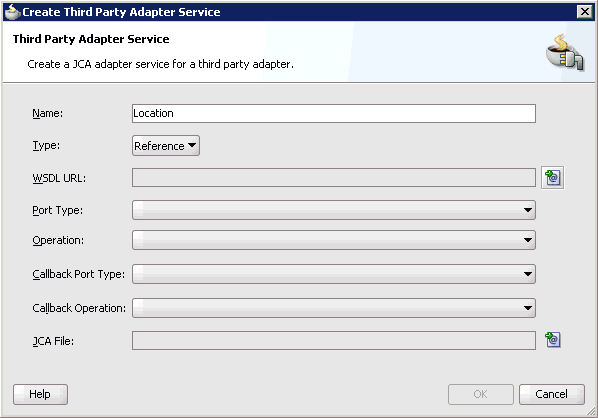
Enter a name for the third party adapter service.
Ensure that Reference is selected from the Type list (default).
Click the Find existing WSDLs icon, which is located to the right of the WSDL URL field.
The SOA Resource Browser dialog is displayed, as shown in Figure 6-6.
Browse and select an outbound PeopleSoft WSDL file from the following directory:
<ADAPTER_HOME>\soa\thirdparty\ApplicationAdapters\wsdls
Click OK.
The Localize Files dialog is displayed, as shown in Figure 6-7.
Click OK.
The outbound WSDL file and associated request and response XML schema files (.xsd) are imported to the project folder that has been created.
You are returned to the Create Third Party Adapter Service dialog, as shown in Figure 6-8.
Figure 6-8 Create Third Party Adapter Service Dialog
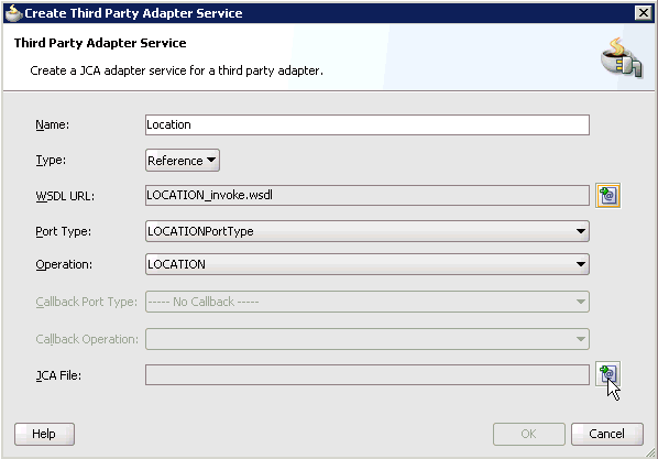
Click the Find JCA file icon, which is located to the right of the JCA File field.
The SOA Resource Browser dialog is displayed, as shown in Figure 6-9.
Browse and select the JCA properties file from the following directory:
<ADAPTER_HOME>\soa\thirdparty\ApplicationAdapters\wsdls
Click OK.
The following message is displayed, as shown in Figure 6-10.
Click Yes.
A copy of the JCA properties file is made in the project folder.
You are returned to the Create Third Party Adapter Service dialog, as shown in Figure 6-11.
Figure 6-11 Create Third Party Adapter Service Dialog
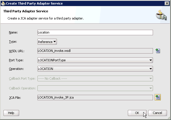
Click OK.
The third party adapter service component (Location) is created and displayed in the External References pane, as shown in Figure 6-12.
Figure 6-12 Third Party Adapter Service Component
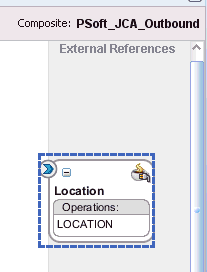
You are now ready to configure an outbound BPM process component.
Configuring an Outbound BPM Process Component
Perform the following steps to configure an outbound BPM process component:
Drag and drop the BPMN Process component from the Service Components pane to the Components pane, as shown in Figure 6-13.
The Create BPMN Process dialog is displayed, as shown in Figure 6-14.
Accept the default option that is selected in the Type area (Asynchronous Service) and click Finish.
The BPMN Process component is created, as shown in Figure 6-15.
Double-click the BPMN Process component in the Components pane.
The BPMN process is displayed, as shown in Figure 6-16.
Click the Activity icon, as shown in Figure 6-17.
Drop the Activity icon on the wire between the Start and End event components, as shown in Figure 6-18.
The Properties - Activity dialog is displayed, as shown in Figure 6-19.
Click the Implementation tab.
Select Service Task from the Implementation Type list, as shown in Figure 6-20.
Select Service Call from the Implementation list, as shown in Figure 6-21.
Click the Browse icon to the right of the Name field, as shown in Figure 6-22.
The Type dialog is displayed, as shown in Figure 6-23.
Select the Third Party Service that has been created for PeopleSoft (for example, Location) and click OK.
You are returned to the Properties - Activity dialog, as shown in Figure 6-24.
Select the Use Associations option that is located under Data Associations.
Click the Edit Data Associations icon.
The Data Associations dialog is displayed, as shown in Figure 6-25.
Right-click the Process node in the right pane and select Add.
The Create Data Object dialog is displayed, as shown in Figure 6-26.
Enter a name in the Name field (for example, Request) and click on the drop-down button in the Type field and select <Component> from the list.
The Create Data Object dialog is displayed, as shown in Figure 6-27.
Click on the Browse button below the Type field, as shown in Figure 6-28.
The Browse window opens, as shown inFigure 6-29.
Select the first component (for example, PS8) and click OK.
You are returned to the Create Data Object dialog, as shown in Figure 6-30.
Click OK.
The Data Object (for example, Request) that has been created is displayed under the Process node in the Data Associations dialog, as shown in Figure 6-31.
Create another Data Object by right-clicking the Process node in the right pane and selecting Add, as shown in Figure 6-32.
Figure 6-32 Add Option in Data Associations Dialog

The Create Data Object dialog is displayed, as shown in Figure 6-33.
Enter a name in the Name field (for example, Response) and click the drop-down button in the Type field and select <Component> from the list.
The Create Data Object dialog is displayed, as shown in Figure 6-34.
Click on the Browse icon below the Type field, as shown in Figure 6-35.
The Browse window opens as shown in Figure 6-36.
Select the second component (for example, PS81) and click OK.
You are returned to the Create Data Object dialog, as shown in Figure 6-37.
Click OK.
The Data Object (for example, Response) that has been created is displayed under the Process node in the Data Associations dialog, as shown in Figure 6-38.
Select the Request Data Object under the Process node in the right pane and drag it to the field below the Inputs area, as shown in Figure 6-39.
Select the Response Data Object under the Process node in the right pane and drag it to the field below the Outputs area, as shown in Figure 6-40.
Click OK.
You are returned to the Properties - Activity dialog, as shown in Figure 6-41.
Click OK.
The Service Task is created between the Start and End Event components, as shown in Figure 6-42.
Save the process and double-click the Start event component.
The Properties - Start dialog is displayed, as shown in Figure 6-43.
Click the Implementation tab, as shown in Figure 6-44.
Click the Plus icon to the right of the Arguments Definition field.
The Create Argument dialog is displayed, as shown in Figure 6-45.
Enter a name in the Name field (for example, argument1) and click on the drop-down button in the Type field and select <Component> from the list.
The Create Argument dialog is displayed, as shown in Figure 6-46.
Click on the Browse icon below the Type field, as shown in Figure 6-47.
Select the first component (for example, PS8) and click OK.
You are returned to the Create Argument dialog, as shown in Figure 6-48.
Click OK.
You are returned to the Properties - Start dialog, as shown in Figure 6-49.
Select the Use Associations option that is located under Data Associations.
Click the Edit Data Associations icon.
The Data Associations dialog is displayed, as shown in Figure 6-50.
Select the Request Data Object under the Process node in the right pane and drag it to the field below the Outputs area.
Click OK.
You are returned to the Properties - Activity dialog, as shown in Figure 6-51.
Click OK.
You are returned to the Process workspace area, as shown in Figure 6-52.
Double-click composite.xml in the left pane.
Click the Save All icon in the menu bar to save the new outbound BPM process component that was configured.
You are now ready to create a File adapter for the write operation.
Creating a File Adapter for the Write Operation
Perform the following steps to create a File adapter for the write operation:
Drag and drop the File Adapter component from the Service Adapters pane to the External References pane, as shown in Figure 6-53.
The Adapter Configuration Wizard is displayed, as shown in Figure 6-54.
Click Next.
The Service Name page is displayed, as shown in Figure 6-55.
Type a name for the new File adapter in the Service Name field and click Next.
The Adapter Interface page is displayed, as shown in Figure 6-56.
Ensure that the Define from operation and schema (specified later) option is selected.
Click Next.
The Operation page is displayed, as shown in Figure 6-57.
Select Write File from the list of Operation Type options and specify an Operation Name (for example, Write).
Click Next.
The File Configuration page is displayed, as shown in Figure 6-58.
Specify a location on your file system where the output file is written.
In the File Naming Convention field, specify a name for the output file.
Click Next.
The Messages page is displayed, as shown in Figure 6-59.
Click Browse, which is located to the right of the URL field.
The Type Chooser dialog is displayed, as shown in Figure 6-60.
Expand Project Schema Files and LOCATION_invoke_response.xsd.
Select the available schema (for example, PS8).
Click OK.
You are returned to the Messages page, as shown in Figure 6-61.
Click Next.
The Finish page is displayed, as shown in Figure 6-62.
Click Finish.
The File Adapter service is created in the External References pane, as shown in Figure 6-63.
Double-click the BPMN Process component.
The BPMN process is displayed, as shown in Figure 6-64.
Click the Activity icon.
Drop the Activity icon on the wire between the Service Task and End event components, as shown in Figure 6-65.
The Properties - Activity dialog is displayed, as shown in Figure 6-66.
Click the Implementation tab.
Select Service Task from the Implementation Type list, as shown in Figure 6-67.
Select Service Call from the Implementation list, as shown in Figure 6-68.
Click the Browse icon to the right of the Name field, as shown in Figure 6-69.
The Type dialog is displayed, as shown in Figure 6-70.
Select the service for write operation that has been created (for example, Write_file) and click OK.
You are returned to the Properties - ServiceTask1 dialog, as shown in Figure 6-71.
Figure 6-71 Properties - ServiceTask1 Dialog
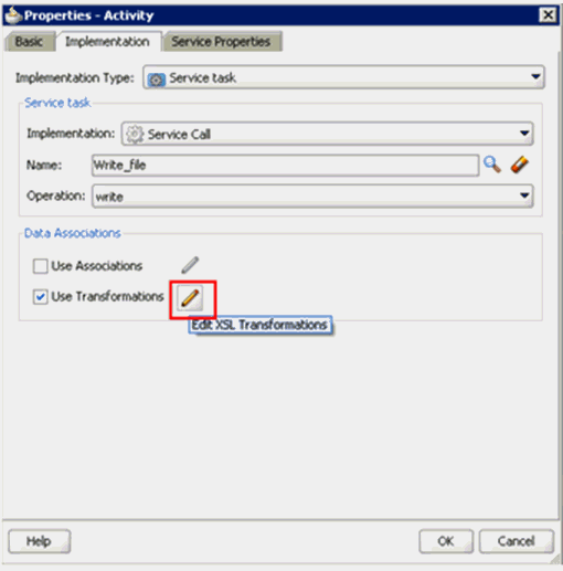
Select the Use Transformations option that is located under Data Associations.
Click the Edit Transformations icon.
The Edit Transformations dialog is displayed, as shown in Figure 6-72.
Click the Plus icon.
The Create Transformation dialog is displayed, as shown in Figure 6-73.
Select the Response Data Object that was created from the Sources list, as shown in Figure 6-74.
Click the Plus icon so that the Data Object 'Response' is added to the Selected Elements area.
Accept the default value that is selected in the Target list, as shown in Figure 6-74.
Leave the default name displayed in the Create field and click OK.
You are returned to the Edit Transformations dialog, as shown in Figure 6-75.
Click OK.
You are returned to the Properties - Activity dialog, as shown in Figure 6-76.
Click OK.
The Response_body.xsl tab is displayed, as shown in Figure 6-77.
Automap the Source and Target elements.
The Auto Map Preferences dialog is displayed, as shown in Figure 6-78.
Accept the default values and click OK.
The transformation is completed, as shown in Figure 6-79.
Save the transformation.
Return to the Process workspace area, as shown in Figure 6-80.
The ServiceTask1 component is created between the ServiceTask component and the End event component.
Save the process.
Double-click the End event component.
The Properties - End dialog is displayed, as shown in Figure 6-81.
Click the Implementation tab.
Select None from the Implementation Type list, as shown in Figure 6-82.
Click OK.
You are returned to the Process workspace area, as shown in Figure 6-83.
Save the Process and double-click the composite.xml file, as shown in Figure 6-84.
Click the Save All icon in the menu bar to save the new outbound BPM process component that was configured.
You are now ready to deploy the outbound BPM process.
Perform the following steps to deploy the BPM outbound process.
Right-click the project name in the left pane (for example, PSoft_JCA_Outbound), select Deploy, and then click PSoft_JCA_Outbound, as shown in Figure 6-85.
The Deployment Action page is displayed, as shown in Figure 6-86.
Ensure that Deploy to Application Server is selected.
Click Next.
The Deploy Configuration page is displayed, as shown in Figure 6-87.
Leave the default values selected and click Next.
The Select Server page is displayed, as shown in Figure 6-88.
Select an available application server that was configured and click Next.
The SOA Servers page is displayed, as shown in Figure 6-89.
Select a target SOA server and click Next.
The Summary page is displayed, as shown in Figure 6-90.
Review and verify all the available deployment information for your project and click Finish.
The process is deployed successfully, as shown in Figure 6-91.
Figure 6-91 Successful Deployment Message

Perform the following steps to invoke the input XML document in the Oracle Enterprise Manager console.
Logon to the Oracle Enterprise Manager console, as shown in Figure 6-92.
Figure 6-92 Oracle Enterprise Manager Console
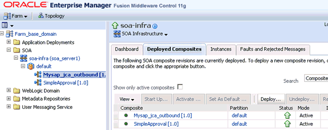
Expand your domain in the left pane followed by the SOA folder.
Select an available project (for example, PSoft_JCA_Outbound).
Click Test.
Click the Request tab.
Provide an appropriate input value in the Value field and click Test Web Service.
A response is received in the Response tab to indicate that invocation was successful in the Oracle Enterprise Manager console.
Navigate to the defined output directory on your file system and open the XML response document that was received.
The XML response document contains the generated output with values.
This section demonstrates how Oracle Application Adapter for PeopleSoft integrates with PeopleSoft to receive event data.
Samples have been provided for this usecase scenario in the etc/sample folder in the Application Adapters installation.
The following tools are required to complete your adapter design-time configuration:
Oracle Adapter Application Explorer (Application Explorer)
Oracle JDeveloper BPM Designer (JDeveloper) or Eclipse
|
Note: The examples in this chapter demonstrate the use of JDeveloper. |
Before you design a BPM process, you must generate the respective WSDL file using Application Explorer. For more information, see "Generating WSDL for Event Integration".
Perform the following steps to create an empty composite for BPM:
Create a new BPM application.
Enter a name for the new BPM application and click Next, as shown in Figure 6-93.
The Name your project page is displayed, as shown in Figure 6-94.
Enter a project name (for example, PSoft_JCA_Inbound) and click Next.
The Configure SOA settings page is displayed, as shown in Figure 6-95.
From the Composite Template list, select Empty Composite and click Finish.
This section describes how to define a BPM inbound process, which consists of the following stages:
Configuring a Third Party Adapter Service Component
Configuring an Inbound BPM Process Component
Creating a File Adapter for the Write Operation
Configuring a Third Party Adapter Service Component
Perform the following steps to create a third party adapter service component:
Drag and drop the Third Party Adapter component from the Service Adapters pane to the Exposed Services pane, as shown in Figure 6-96.
Figure 6-96 Third Party Adapter Component
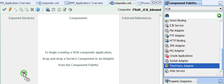
The Create Third Party Adapter Service dialog is displayed, as shown in Figure 6-97.
Figure 6-97 Create Third Party Adapter Service Dialog
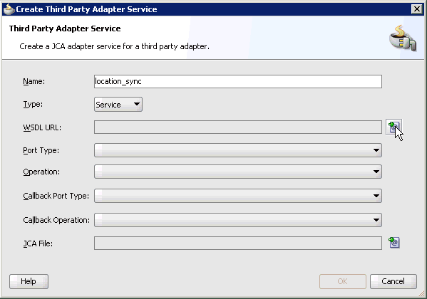
Enter a name for the third party adapter service.
Ensure that Service is selected from the Type list (default).
Click the Find existing WSDLs icon, which is located to the right of the WSDL URL field.
The SOA Resource Browser dialog is displayed, as shown in Figure 6-98.
Browse and select an inbound WSDL file from the following directory:
<ADAPTER_HOME>\soa\thirdparty\ApplicationAdapters\wsdls
Click OK.
The Localize Files dialog is displayed, as shown in Figure 6-99.
Click OK.
The inbound WSDL file and associated receive_request XML schema file (.xsd) are imported to the project folder that has been created.
You are returned to the Create Third Party Adapter Service dialog, as shown in Figure 6-100.
Figure 6-100 Create Third Party Adapter Service Dialog
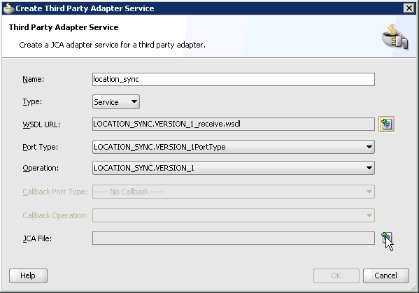
Click the Find JCA file icon, which is located to the right of the JCA File field.
The SOA Resource Browser dialog is displayed, as shown in Figure 6-101.
Browse and select the JCA properties file from the following directory:
<ADAPTER_HOME>\soa\thirdparty\ApplicationAdapters\wsdls
Click OK.
The following message is displayed, as shown in Figure 6-102.
Figure 6-102 Copy File Confirmation Message
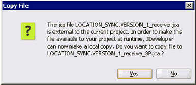
Click Yes.
A copy of the JCA properties file is made in the project folder.
You are returned to the Create Third Party Adapter Service dialog, as shown in Figure 6-103.
Figure 6-103 Create Third Party Adapter Service Dialog
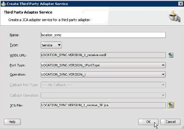
Click OK.
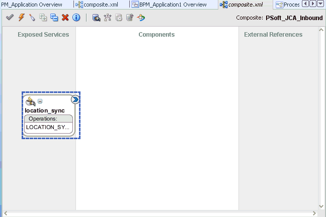
The third party adapter service component (location_sync) is created in the Exposed References pane, as shown in Figure 6-104.
Figure 6-104 Third Party Adapter Service Component
You are now ready to configure an inbound BPM process component.
Configuring an Inbound BPM Process Component
Perform the following steps to configure an inbound BPM process component:
Drag and drop the BPMN Process component from the Service Components pane to the Components pane, as shown in Figure 6-105.
The Create BPMN Process dialog is displayed, as shown in Figure 6-106.
Click on the Manual Process in the Type field as shown in Figure 6-107.
Click Finish.
The BPMN Process component is created, as shown in Figure 6-108.
Double-click the BPMN Process component in the Components pane.
The BPMN process is displayed, as shown in Figure 6-109.
Right-click UserTask and select Delete from the menu.
Double-click the Start event component, as shown in Figure 6-110.
The Properties - Start dialog is displayed, as shown in Figure 6-111.
Click the Implementation tab, as shown in Figure 6-112.
Select Message from the Implementation Type list, as shown in Figure 6-113.
Select Interface from Catalog from the Implementation list.
Click the Browse icon to the right of the Name field, as shown in Figure 6-114.
The Type dialog is displayed, as shown in Figure 6-115.
Select the Third Party Service that has been created and click OK.
You are returned to the Properties - Start dialog, as shown in Figure 6-116.
Select the Use Associations option that is located under Data Associations.
Click the Edit Data Associations icon.
The Data Associations dialog is displayed, as shown in Figure 6-117.
Right-click the Process node in the right pane and select Add.
The Create Data Object dialog is displayed, as shown in Figure 6-118.
Enter a name in the Name field (for example, location_sync_in) and click on the drop-down button in the Type field and select <Component> from the list.
The Create Data Object dialog is displayed, as shown in Figure 6-119.
Click on the Browse icon below the Type field, as shown in Figure 6-120.
The Browse window opens as shown in Figure 6-121.
Select the first component (for example, LOCATION_SYNC) and click OK.
You are returned to the Create Data Object dialog, as shown in Figure 6-122.
Click OK.
The Data Object (for example, location_sync_in) that has been created is displayed under the Process node in the Data Associations dialog, as shown in Figure 6-123.
Select the location_sync_in Data Object under the Process node in the right pane and drag it to the field below the Outputs area.
Click OK.
You are returned to the Properties - Start dialog, as shown in Figure 6-124.
Click OK.
You are returned to the Process workspace area, as shown in Figure 6-125.
Double-click composite.xml in the left pane.
Click the Save All icon in the menu bar to save the new inbound BPM process component that was configured.
You are now ready to create a File adapter for the write operation.
Creating a File Adapter for the Write Operation
Perform the following steps to create a File adapter for the write operation:
Drag and drop the File Adapter component from the Service Adapters pane to the External References pane, as shown in Figure 6-126.
The Adapter Configuration Wizard is displayed, as shown in Figure 6-127.
Figure 6-127 Adapter Configuration Wizard
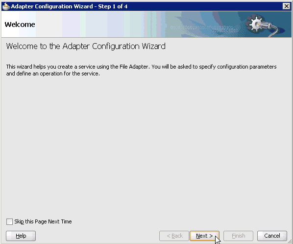
Click Next.
The Service Name page is displayed, as shown in Figure 6-128.
Type a name for the new File adapter in the Service Name field and click Next.
The Adapter Interface page is displayed, as shown in Figure 6-129.
Ensure that the Define from operation and schema (specified later) option is selected.
Click Next.
The Operation page is displayed, as shown in Figure 6-130.
Select Write File from the list of Operation Type options and specify an Operation Name (for example, Write).
Click Next.
The File Configuration page is displayed, as shown in Figure 6-131.
Specify a location on your file system where the output file is written.
In the File Naming Convention field, specify a name for the output file.
Click Next.
The Messages page is displayed, as shown in Figure 6-132.
Click browse for schema file, which is located to the right of the URL field.
The Type Chooser dialog is displayed, as shown in Figure 6-133.
Expand Project Schema Files and LOCATION_SYNC.VERSION_1_receive_request.xsd.
Select the available schema (for example, LOCATION_SYNC).
Click OK.
You are returned to the Messages page, as shown in Figure 6-134.
Click Next.
The Finish page is displayed, as shown in Figure 6-135.
Click Finish.
The File Adapter service is created in the External References pane, as shown in Figure 6-136.
Double-click the BPMN Process component.
The BPMN process is displayed, as shown in Figure 6-137.
Click the Activity icon.
Drop the Activity icon on the wire between the Start and End event components, as shown in Figure 6-138.
The Properties - Activity dialog is displayed, as shown in Figure 6-139.
Figure 6-139 Properties - Activity Dialog
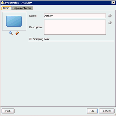
Click the Implementation tab, as shown in Figure 6-140.
Select Service Task from the Implementation Type list, as shown in Figure 6-141.
Select Service Call from the Implementation list.
Click the Browse icon to the right of the Name field, as shown in Figure 6-142.
The Type dialog is displayed, as shown in Figure 6-143.
Select the service for write operation that has been created (for example, PSoft_File_Adapter) and click OK.
You are returned to the Properties - Activity dialog, as shown in Figure 6-144.
Figure 6-144 Properties - Activity Dialog
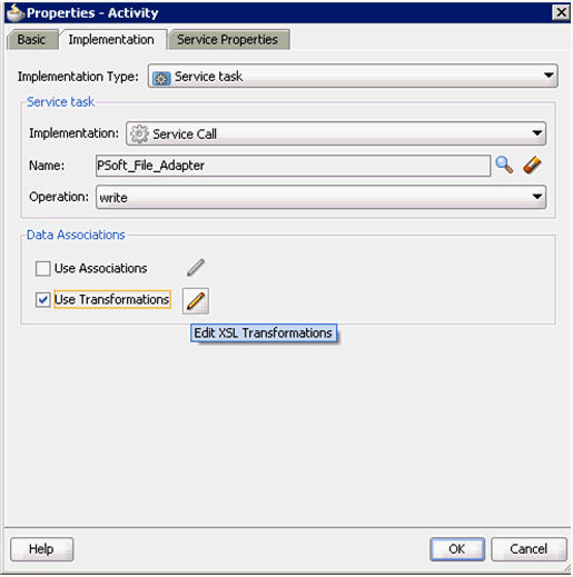
Select the Use Transformations option that is located under Data Associations.
Click the Edit XSL Transformations icon.
The Edit Transformations dialog is displayed, as shown in Figure 6-145.
Click the Plus icon.
The Create Transformation dialog is displayed, as shown in Figure 6-146.
Figure 6-146 Create Transformation Dialog
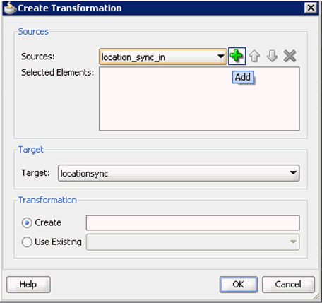
Click the Plus icon so that the Data Object 'location_sync_in' is added to the Selected Elements area, as shown in Figure 6-147.
Accept the default value that is selected in the Target list.
Leave the default name displayed in the Create field and click OK.
You are returned to the Edit Transformations dialog, as shown in Figure 6-148.
Click OK.
You are returned to the Properties - Activity dialog, as shown in Figure 6-149.
Figure 6-149 Properties - Activity Dialog
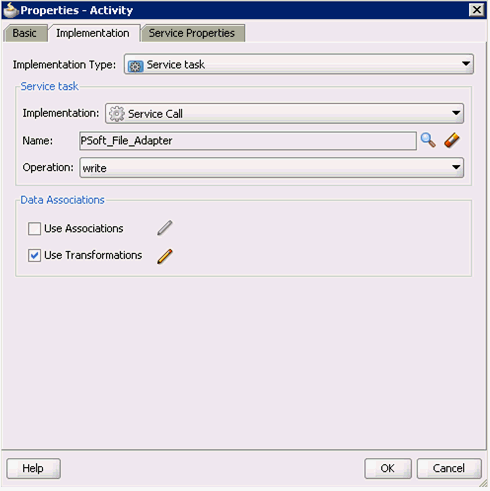
Click OK.
The location_sync_in_body.xsl tab is displayed, as shown in Figure 6-150.
Figure 6-150 location_sync_in_body.xsl Tab

Automap the Source and Target elements.
The Auto Map Preferences dialog is displayed, as shown in Figure 6-151.
Accept the default values and click OK.
The transformation is completed, as shown in Figure 6-152.
Save the transformation.
Return to the Process workspace area, as shown in Figure 6-153.
The ServiceTask component is created between the Start event component and the End event component.
Save the Process and double-click the composite.xml file.
Click the Save All icon in the menu bar to save the new inbound BPM process component that was configured, as shown in Figure 6-154.
You are now ready to deploy the BPM inbound process. You can follow the same procedure that is described in "Deploying the BPEL Inbound Process". Once event messages are triggered through PeopleSoft, output XML is received in the location that was specified for the File adapter component. For more information on how to trigger events in PeopleSoft, see "Triggering an Event in PeopleSoft".