H Clustering for the JD Edwards Transaction Server on WebLogic Server
This appendix discusses these topics:
-
Section H.13, "Associate a JMS Server with a Persistent Store"
-
Section H.14, "Additional Configuration for Using Horizontal Cluster"
H.1 Understanding WebLogic Clustering
Clustering permits the deployment of application components and services to several machines with a single face to the client. When a client requests a service, it should make no difference if the service runs on a single server or across a number of servers. The clustering abstraction provides you with a clear route to improving the performance and scalability of the applications with increased administration of hardware and network resources. WebLogic clustering provides these benefits:
-
Scalability
A clustered solution allows you to create additional capacity by introducing more
servers to the cluster, thereby reducing the load on existing servers. For the JD Edwards EnterpriseOne Transaction Server with the Real Time (RTE) Application, you can add as many servers and messaging engines as you like to meet the performance requirement. The RTE application on WebLogic achieves scalability with the implementation of a messaging engine policy.
-
Load balancing
The ability to distribute requests across all members of the cluster, according to the workload on each server. WebLogic handles load balancing as defined by the Load Balancing Algorithm that you configure on cluster setup. The Transaction Server with RTE on WebLogic only supports round-robin load balancing policy for the RTE application.
-
High availability
A mix of features that ensure applications and services are available even if a server or machine fails. Clients can continue to work with little or no disruption in a highly available environment. RTE on WebLogic achieves high availability with the implementation of a messaging engine policy.
H.2 Creating a Cluster on WebLogic Server
For advanced configuration of the Oracle WebLogic Server refer to this link:
http://download.oracle.com/docs/cd/E15523_01/web.1111/e13709/setup.htm
The section discusses these topics:
-
Creating the Servers
-
Creating Machines
-
Associate Machines with Servers
-
Cluster the Servers
-
Setup the Cluster for Load Balancing
-
Setup the Cluster for Failover
H.3 Creating the Servers
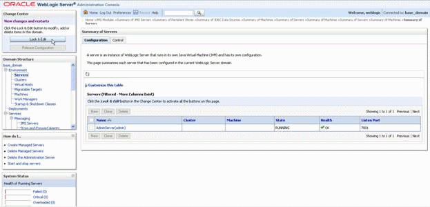
Description of the illustration image001.gif
-
On Summary of Servers, click the Lock and Edit button at the bottom of the page.
Description of the illustration image002.gif
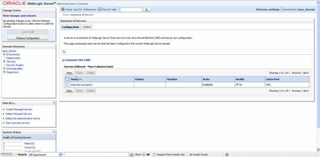
-
On Summary of Servers, click the New Button.
Description of the illustration image003.gif
-
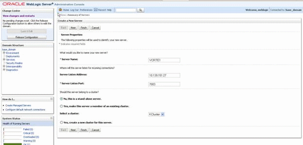
On Create a New Server, complete these fields:
-
Server Name
Enter the name of the new server.
-
Server Listen Address
Enter the IP address of the physical machine on which this instance will run.
Note:
If you want to setup a horizontal Cluster, you should create a server with the remote Server Listen Address. -
Server Listen Port
Enter a valid unused port on which this server will listen.
Note:
If you want to setup a horizontal Cluster, you should create a server with a Remote Server Listen Port.
-
-
On Create a New Server, with the entered values accepted, click the Finish button.
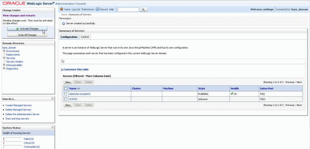
Description of the illustration image005.gif
-
On Create a New Server, click the Activate Changes button at the bottom of the screen.
-
Repeat the steps this procedure for any additional servers you want to make part of the cluster.
-
If you want to setup a horizontal Cluster, you should create a server with the remote Server listen Address and Remote Server Listen Port.
When you complete this procedure, your list of server will be similar to this:
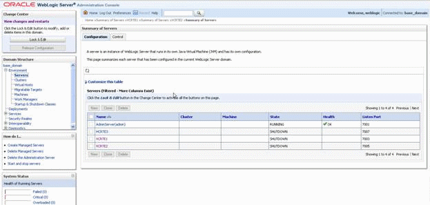
Description of the illustration image006.gif
H.4 Creating Machines
Use this procedure to create the machines:
-
Click Environment > Machines > Lock & Edit.
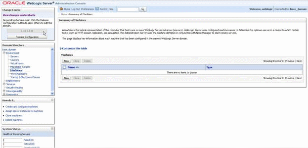
Description of the illustration image007.gif
-
On Summary of Machines, click the New button.
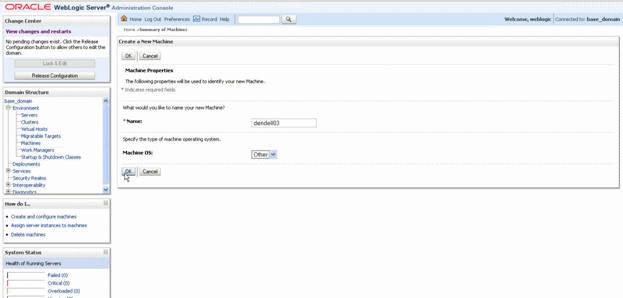
Description of the illustration image008.gif
-
On Create a New Machine, complete these fields:
-
Name
Enter the machine name of the host for this clustered server.
-
Machine OS
Use the pulldown to select the operating system. Choose Other for all non-UNIX operating systems.
-
-
On Create a New Machine, click the OK button.
-
Click Activate Changes.
-
Repeat the steps in this procedure if your cluster spans multiple machines or if multiple server instances will run on individual machines in the cluster.
When you complete this procedure, your list of server will be similar to this:
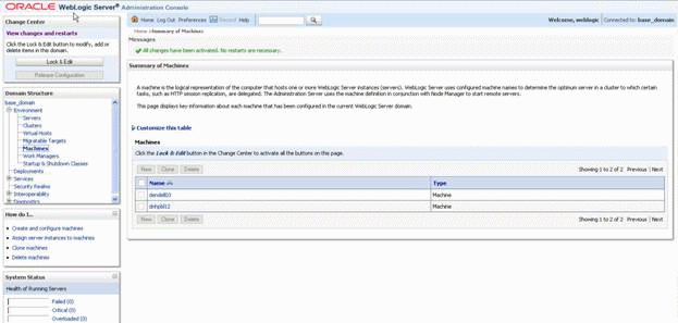
Description of the illustration image009.gif
Note:
For the Horizontal Node ensure that the listen address for the server and the machine are exactly the same. This should be the ip of the physical machine, not "localhost" or 127.0.0.1.
H.5 Associate Machines with Servers
Use this procedure to associate machines with Servers:
-
Go to Environment > Machines.
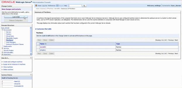
Description of the illustration image010.gif
-
On Summary of Machines, click the Lock & Edit button at the bottom of the screen.
Description of the illustration image011.gif
-
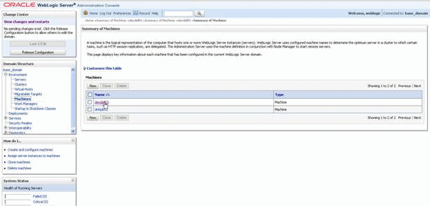
In the Machines list, select the machine for the vertical nodes. If setting up horizontal cluster, select the machine for the horizontal node.
Description of the illustration image012.gif
-
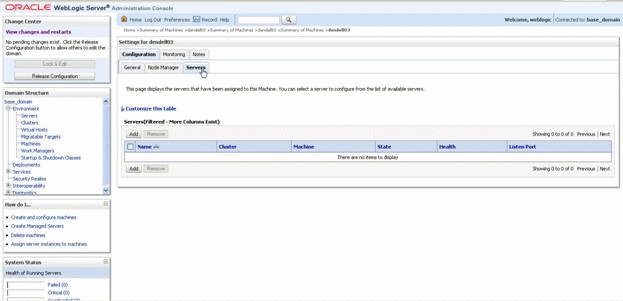
In Settings for <machine>, click on the Servers tab.
Description of the illustration image013.gif
-
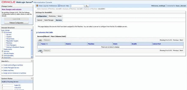
In Customize this table, click the Add button.
Description of the illustration image014.gif
-
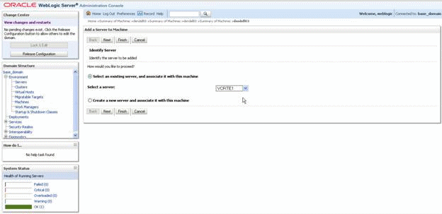
On Identify Server, complete these fields:
-
Check this radio button:
Select an existing server, and associate it with this machine
-
Select a server:
Use the pulldown to select an existing server.
-
-
Repeat the steps in this procedure if your cluster spans multiple machines or if multiple server instances will run on individual machines in the cluster.
-
Click the Finish button.
-
Click the Activate Changes button.
When you complete this procedure, your list of server will be similar to this:
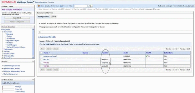
Description of the illustration image015.gif
H.6 Cluster the Servers
Use this procedure to cluster the servers.
-
Go to Environment > Clusters.
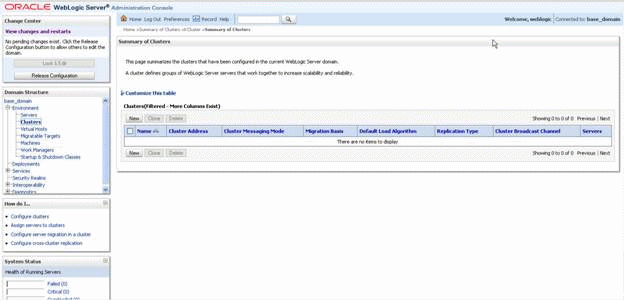
Description of the illustration image016.gif
-
On Summary of Clusters, click the Lock & Edit button at the bottom of the screen.
-
Click the New button.
Description of the illustration image017.gif
-
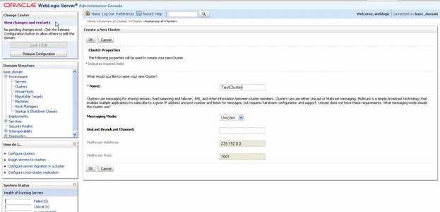
On Cluster Properties, complete these fields:
-
Name
Enter a name for the cluster.
-
Messaging Mode
Use the pulldown to select Unicast.
-
Unicast Broadcast Channel
Leave this field blank.
-
Multicast Address
Accept the default value.
-
Multicast Port
Accept the default value.
-
-
Click the OK button.
Description of the illustration image018.gif
-
On Summary of Clusters, click on the newly-defined cluster name.
Description of the illustration image019.gif
-
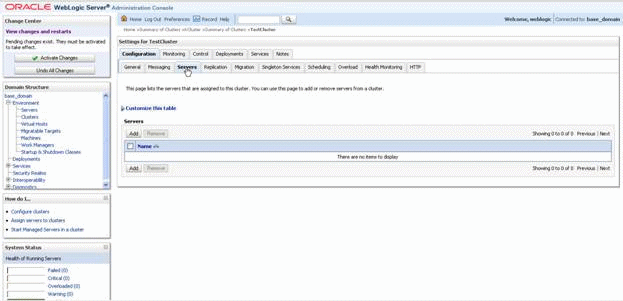
On Settings for <cluster>, click the Servers tab.
-
Click on the Add button.
-
Select the server.
-
Click next.
-
Repeat the preceding two steps for any additional servers.
-
Click the Activate Changes button.
When you complete this procedure, your list of server will be similar to this:
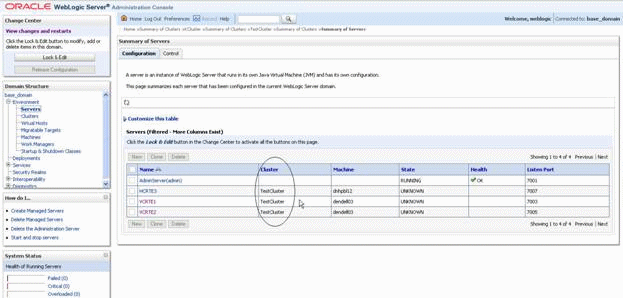
Description of the illustration image020.gif
-
Restart the admin server and all node managers.
H.7 Setup the Cluster for Load Balancing
A cluster is setup with load balancing feature with round-robin algorithm by default. However the algorithm to be used can be changed based on requirement.
-
Go to click Environment > Clusters.
-
Click on the cluster name.
-
Go to General tab.
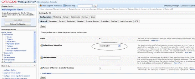
Description of the illustration image021.gif
-
Click the Lock & Edit button.
-
Default Load Algorithm field contains several algorithms in the dropdown. Select the one you want to use. Different load balancing algorithms are round-robin, weight-based and random.
-
Click the Save button.
-
Click the Activate Changes button.
H.8 Setup the Cluster for Failover
A cluster is setup with load balancing feature with round-robin algorithm by default. However the algorithm to be used can be changed based on requirement.
-
Go to Environment > Clusters.
-
Click on the cluster name.
-
Go to Migration tab
-
Click the Lock & Edit button.
-
In the Candidate Machines For Migratable Servers field, move the machines Available to Choose.
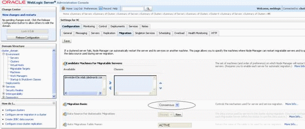
Description of the illustration image022.gif
-
On Settings for VC, with the Configuration tab selected, complete this field:
-
Migration Basis
Use the pulldown to select Consensus.
Note:
You can also select database as Migration Basis with additional setup.
-
-
Click Environment, Migratable Targets.
-
Click on the migratable target.
-
Go to Migration tab.
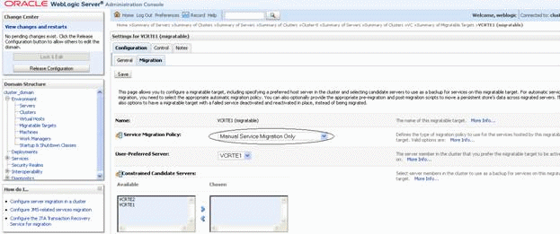
Description of the illustration image023.gif
-
On Settings for <machine> (migratable), with the Migration tab selected, complete this field:
-
Server Migration Policy
Use the pulldown to select between these available policies:
-
Manual Service Migration Only
-
Auto-Migrate Exactly-Once Services
-
Auto-Migrate Failure-Recovery Services
-
-
-
Click the Save button.
-
Click the Activate Changes button.
H.9 Installing the Transaction Server RTE Component on WebLogic Server using Server Manager
Use this procedure to install the RTE application to the cluster via Server Manager.
-
Install the JD Edwards EnterpriseOne product Server Manager on a machine with the Microsoft Windows operating system.
-
Install the Server Manager agent on the machine that is running the Oracle WebLogic Administration Console.
-
Register the WebLogic server through Server Manager.
-
Logon to the Server Manager console.
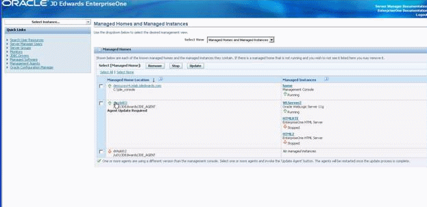
Description of the illustration image024.gif
-
On Managed Homes and Managed Instances, click on the machine running the registered Oracle WebLogic Server.
Description of the illustration image025.gif
-
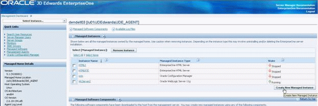
Click the Create New Managed Instance button.
Description of the illustration image026.gif
-
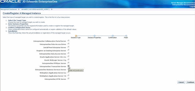
On Create/Register A Managed Instance, Instance Type, click this radio button:
EnterpriseOne Transaction Server
-
Click the Continue button.
Description of the illustration image027.gif
-
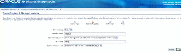
On Create/Register A Managed Instance, Instance Properties, complete the fields:
-
Server Group
Accept the default value.
-
Instance Name
Enter an instance name.
-
J2EE Server/Cluster
Use the pulldown to select the Oracle WebLogic cluster.
-
HTTP Port
Accept the auto populated value.
Note:
You should not manually change this value. -
Software Component
Use the pulldown to select a valid JD Edwards RTE application software component for your installation.
-
-
Click the Continue button.
Description of the illustration image028.gif
-
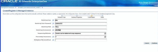
On Create/Register A Managed Instance, Confirmation, complete these fields:
-
Bootstrap User
Enter any value that you will use for this user.
-
Bootstrap User Password
Enter a password.
-
Bootstrap Role
Enter the JD Edwards EnterpriseOne role for the bootstrap user. For example, *ALL is a valid role.
-
Sequencing Behavior
Use the pulldown to select the desired behavior.
-
Processing Concurrency
Use the pulldown to select the desired processing concurrency value. This defines the number of concurrent event processing threads to run.
-
WebSphereMQ Initial Root
Leave this value blank; it is not applicable to WebLogic installations.
-
-
Click the Continue button.
Description of the illustration image029.gif
-
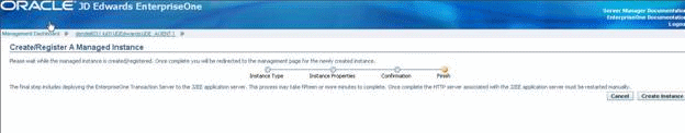
On Create/Register A Managed Instance, Finish, click the Create Instance button.
Description of the illustration image030.gif
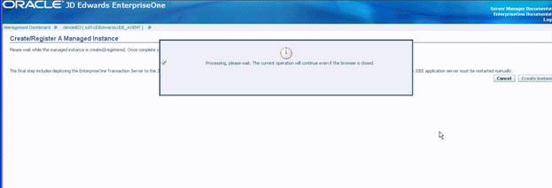
Server Manager displays a processing message.
Description of the illustration image031.gif
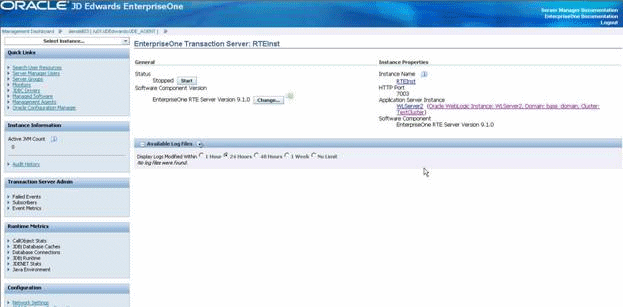
The instance screen for the RTE application displays.
Caution:
Do not attempt to start the instance at this time. You must continue with the setup instructions in this guide until you are explicitly instructed to start the instance.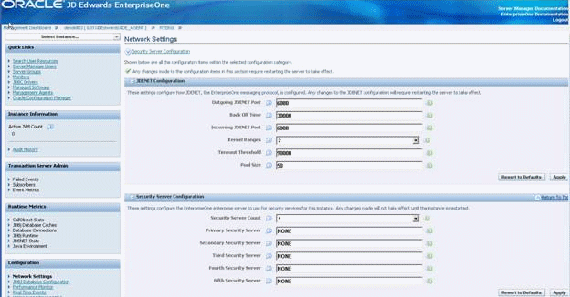
Description of the illustration image032.gif
-
In the Configuration section, click Network Settings and complete the fields as applicable for your environment.
Description of the illustration image033.gif
-
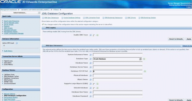
In the Configuration section, click JDBJ Database Configuration and complete the fields as applicable for your environment.
Description of the illustration image034.gif
-
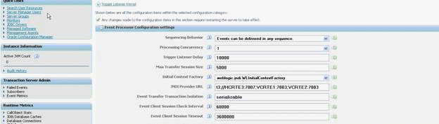
In the Configuration section, click Event Processor Configuration settings and confirm the fields are valid for your installation.
Caution:
Do not attempt to start the instance at this time. You must continue with the setup instructions in this guide until you are explicitly instructed to start the instance.
H.10 Using JDBC Persistent Stores
Follow the steps below to modify the installed configuration for using JDBC Persistent Stores instead of FileStore. In order to use horizontal clusters, it is mandatory to use JDBC Persistent Stores for JMS Servers.
Caution:
Do not attempt to start the Transaction Server RTE instance or any other managed servers at this time. You must continue with the setup instructions in this guide until you are explicitly instructed to start an instance or managed server.These instructions assume that you've already created a database to serve as a persistent store.
This chapter discusses these topics:
H.11 Create JDBC Datasources
Use this procedure to create JDBC Datasources.
-
Logon to the WebLogic Administration Console.
-
Go to Services > Data Sources.
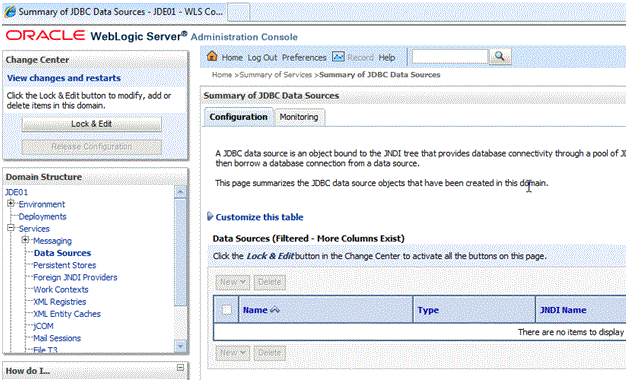
Description of the illustration jdbc_data_sources.gif
-
On Summary of JDBC Data Sources, click the Lock & Edit button.
Description of the illustration jdbc_data_sources_2.gif
-
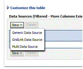
On Summary of JDBC Data Sources, in the Customize this table section, use the New pulldown to select Generic Data Source.
Description of the illustration image037.gif
-
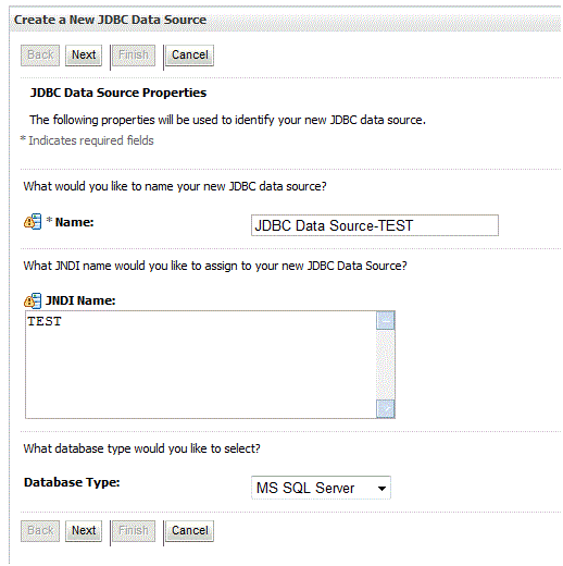
On Create a New JDBC Data Source, JDBC Data Source Properties, complete these fields:
-
Name
Enter a name for the JDBC data source.
-
JNDI Name
Enter a name for the JNDI.
-
Database Type
Use the pulldown to select your database type.
-
-
Click the Next button.
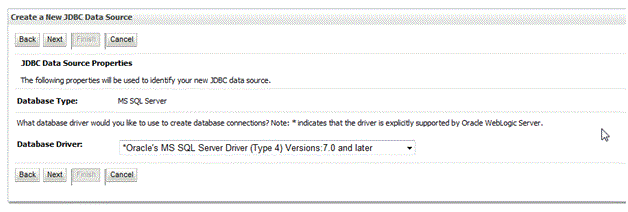
Description of the illustration select_db_driver_2.gif
-
On Create a New JDBC Data Source, use the pulldown to select the driver appropriate for your database.
Note:
For Oracle databases, you must select the thin driver. You cannot use an XA driver. -
Click the Next button.
Description of the illustration select_db_driver_3.gif
-
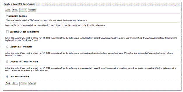
On Create a New JDBC Data Source, Transaction Options, deselect this checkbox:
Supports Global Transactions
-
Click the Next button.
Description of the illustration image039.gif
-
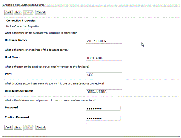
On Create a New JDBC Data Source, Connection Properties, complete these fields:
-
Database Name
Enter a name for the database to which you want to connect.
-
Host Name
Enter the name or IP address of the database server.
-
Port
Enter the port on the database server which is used to connect.
-
Database User Name
Enter the database account you want to use to create the database connections.
-
Password
Enter the database account password to use to create database connections.
-
Confirm Password
Confirm the database account password.
-
-
Click the Next button.
Description of the illustration image040.gif
-
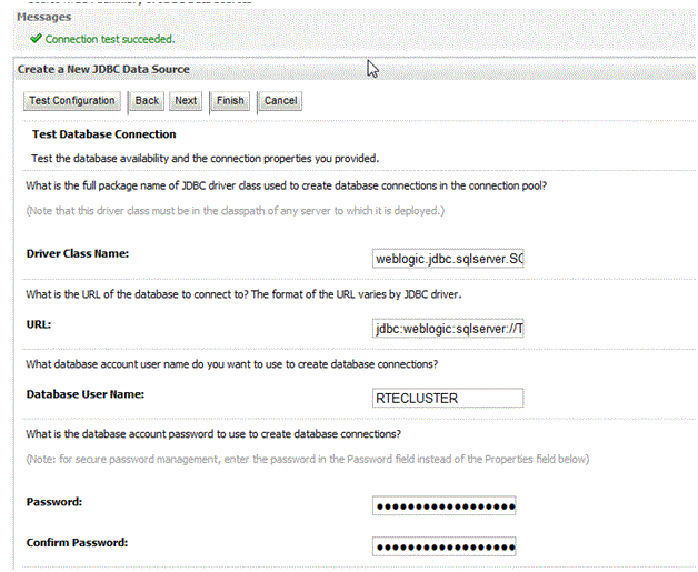
On Create a New JDBC Data Source, Test Database Connection, click the Test Configuration button.
-
Ensure you receive this message: connection test succeeded
-
Click the Next button.
Description of the illustration image041.gif
-
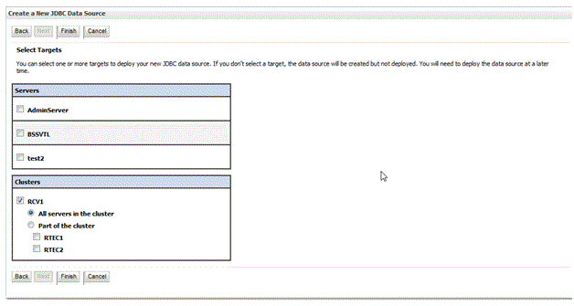
On Summary of JDBC Data Sources, in the list of Data Sources (Filtered - More Columns Exist), select the checkboxes for all servers in the cluster.
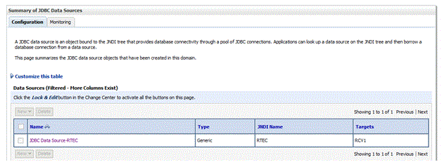
Description of the illustration summary_jdbc_dsources.gif
-
Click the Finish button at the bottom of the page.
-
Repeat the applicable steps in this procedure to add additional JDBC data sources.
-
Click Activate changes.
H.12 Create JDBC Persistent Stores
Server Manager deploys the RTE solution with file persistent stores already created. This works for vertical clusters, but should be changed to JDBC type persistent stores for horizontal clusters.
Use this procedure to create the necessary JDBC persistent stores.
-
Go to Services > Persistent Stores.
Description of the illustration image035.gif
-
On Summary of Persistent Stores, click the Lock & Edit Button.
Description of the illustration persistent_stores.gif
-
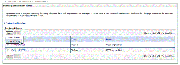
On Summary of Persistent Stores, in the Customize this table section, click the New pulldown and on the flyout choose Create JDBCStore.
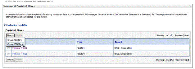
Description of the illustration persistent_stores_2.gif
-
On Settings for JDBCStore, complete these fields:
-
Name
Enter a name for the JDBC store. The name must be unique within the WebLogic Server instance or its cluster.
-
Target
Use the pulldown to select the migratable server. The list will show of all WebLogic Server instances that have been defined in the current domain and are therefore candidates for hosting this JDBC store.
-
Data Source
Use the pulldown to select the JDBC data source used by this JDBC store to access its backing table.
Caution:
The list will only show JDBC datasources that:-
Do not use global transactions.
-
Do not use a non XA JDBC driver.
-
Are not configured to enable Logging Last Resource
-
Are not configured to Emulate Two-Phase Commit
-
-
Prefix Name
Leave this field blank.
-
-
Click the Save button.
-
Click the OK button.
-
Repeat the applicable steps to add additional persistent stores for additional JMS servers.
-
Click the Activate Changes button.
When you complete this procedure, your list of server will be similar to this:
Description of the illustration image045.gif
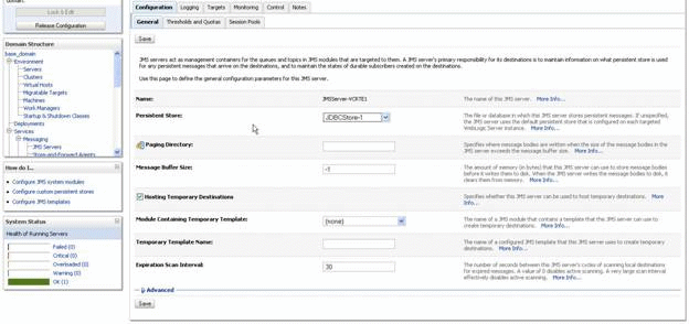
H.13 Associate a JMS Server with a Persistent Store
Server Manager by default associates the JMS Servers with file persistent stores. For using JDBC store or using horizontal cluster, you must associate the JMS Servers with JDBC persistent stores.
Use this procedure to associate a JMS Server with a persistent store:
-
Go to Services > Messaging > JMS Servers.
Description of the illustration image046.gif
-
On Summary of JMS Server, click the Lock & Edit button at the bottom of the page.
Description of the illustration image047.gif
-
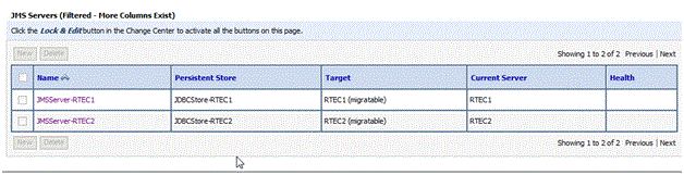
On Summary of JMS Server, in the JMS Servers (Filtered - More Columsn Exist), click on the JMS Server that you want to associate with a persistent store.
Description of the illustration image048.gif
-
Click on the General Tab and complete these fields:
-
Persistent Store
Use the pulldown to select the JDBC Store to which you want to associate.
-
Paging Directory
Accept the default value.
-
Message Buffer Size
Accept the default value.
-
Hosting Temporary Destinations
Ensure the checkbox for this option is selected.
-
Module Containing Temporary Templates
Accept the default value.
-
Temporary Template Name
Accept the default value.
-
Expiration Scan Interval
Accept the default value.
-
-
Click the Save button.
-
Click the Activate Changes button.
-
Repeat the applicable steps to add JMS Servers and persistent stores.
When you complete this procedure, your list of server will be similar to this:
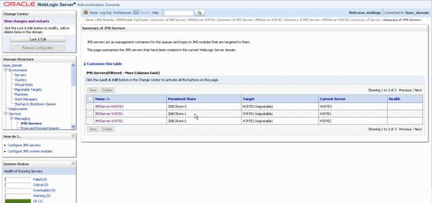
Description of the illustration image049.gif
H.14 Additional Configuration for Using Horizontal Cluster
Server Manager creates the necessary file structure on the node that the WebLogic Administration Console resides on. However, for any horizontal cluster nodes, these files should be transferred manually. On Windows Machines, this should be done through Windows Explorer. For Unix or Linux machines, this should be done through FTP. The steps below use Linux/FTP as an example.
-
Use these steps to determine where the RTE installation is looking for the requisite ini files:
-
Go to Servers > Server_Name.
-
Click on the Server Start tab.
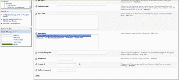
Description of the illustration image050.gif
-
In the Arguments section, note the -
Ddefault_pathstructure.For example, in the above example the structure is:
/u01/JDEdwards/JDE_AGENT/targets/RTEInst/configThis is the directory that is created on the horizontal node and where the necessary files must be copied.
-
On the target machine, you must pre-create the necessary directory structure.
For example:
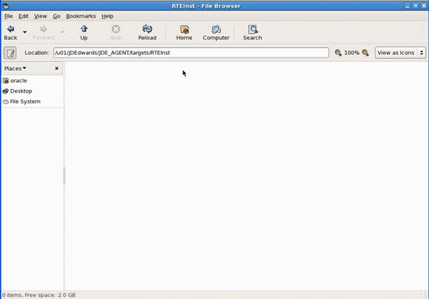
Description of the illustration image051.gif
-
Copy the config files from the vertical node machine to the horizontal node machine.
In the below example, the vertical node machine is dendell03 and the horizontal node machine is dnhpbl12.
Note:
If you are using UNIX or Linux machines, ensure you have the correct permissions for the new directory. For example:chmod 777 -R JDEdwards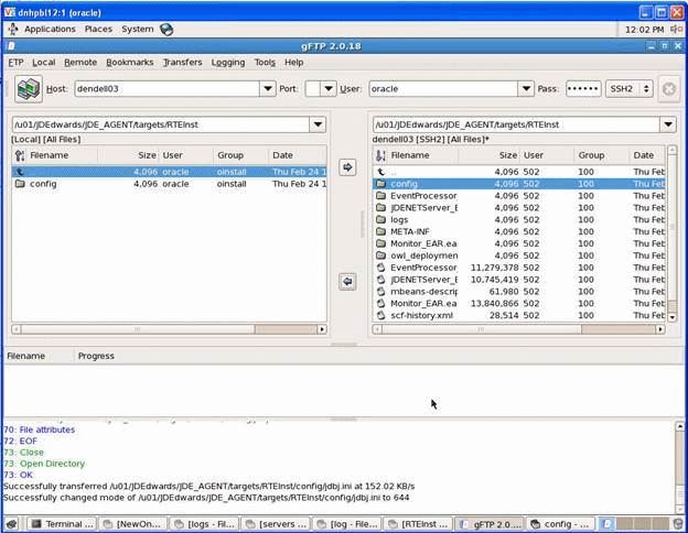
Description of the illustration image052.gif
-