The Sun Ray 3 Plus power LED is illustrated in the following figure.
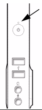
LED colors and states are described in the following table. If the Power LED is green, the unit is functioning normally.
Table 3.8. Sun Ray 3 Plus LED Indicators
State | Meaning |
|---|---|
Off | The unit is not plugged in or not turned on. When the plug is reconnected, the unit is automatically turned On. To turn the unit on manually, touch the ON/OFF switch, located below the LED, or insert a smart card. To turn it off, touch the ON/OFF switch. Note: Turning the unit off or removing a smart card does not affect users' sessions. |
Green | The unit is powered on and is functioning normally. |
Amber | The LED lights for 2-3 seconds or less at power-on while the unit performs diagnostic tests. If the LED remains amber or becomes amber at any other time, the unit may be inoperable and should be reset. To reset the unit, power off and power on the unit by using the power button or by unplugging and replugging the power cord. If the LED remains amber, continue to reset the unit two more times. If the LED remains amber after three resets, the unit is inoperable. Contact your system administrator to replace the unit. |
The Sun Ray 3 Plus Smart Card LED is illustrated in the following figure.
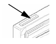
Smart Card LED insertion states are described in the following table.
Table 3.9. Sun Ray 3 Plus Smart Card Insertions States
State | Meaning |
|---|---|
Off | No smart card is inserted or detected. |
On | The smart card has been inserted correctly. |
Blinking | Firmware inside the smart card interface is being updated. This update takes 30 to 40 seconds. |
The Sun Ray 3 Plus Network Connector LEDs are illustrated in the following figure.
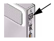
The Ethernet port LEDs indicate network connectivity and speed. The top LED represents the speed of the twisted pair link; the bottom LED shows activity on the link.
Table 3.10. Ethernet Port LED States
State | Meaning |
|---|---|
Top LED Orange | 1 Gbps |
Top LED Green | 100 Mbps |
Top LED Off | 10 Mbps |
Bottom LED Flashing Green | Packets are being received from the network. |
Bottom LED Off | No packets are being received. |