18 Work with Screen Design Aid
This chapter contains these topics:
-
Section 18.17, "Placing Fields on a Screen Using a Pick List"
-
Section 18.21, "Process Overview - Revising the Field Definition"
-
Section 18.22, "Process Overview - Revising Vocabulary and Function Keys"
-
Section 18.23, "Function Keys for Screen and Display Format Control"
18.1 About Screen Design Aid
Screen Design Aid (SDA) is an interactive feature you use to design and maintain screens. This full-screen editor validates your work against the Data Dictionary and adds records to vocabulary overrides. You can work with multiple record formats simultaneously and you can move fields from one format to another.
Below is a list of some features of SDA:
-
Design is conducted in a safe work environment. If you make a mistake you can exit without changing a screen's Data Description Specifications (DDS).
-
Screen specifications are stored in data structures in the QRECOVERY library. This is similar to the IBM recovery of SEU.
-
You can create a screen in normal mode (80 columns by 24 rows) or wide mode (132 columns by 27 rows). You can also design wide screens on 80 column devices using a windowing facility.
-
Answering initial yes/no options allows you to create a basic screen skeleton for a subfile, non-subfile or window-style screen.
-
SDA is fully integrated with the Data Dictionary and vocabulary override files. You can place fields on the screen by referring to a Data Dictionary name and override default attributes, if necessary. You can place vocabulary override fields on the screen and, if desired, modify their contents through the full screen.
-
SDA is fully integrated with the system database. You can select fields from the system database, create a pick list and then reorder fields in the pick list. You can place fields on the screen individually or all at once by pinpointing locations on the full screen with an ampersand (&) or asterisk (*).
-
SDA has full screen capability. You can add, change, move, or delete fields by entering control characters directly on the screen.
-
Unlike the IBM SDA, JD Edwards World SDA allows you to work with multiple record formats at one time. You can display and change any combination of formats simultaneously (as long as they do not overlap). You can also move fields from one format to another.
-
SDA allows you to simulate a screen at program execution time. You can run the simulation for any set of conditioning indicators to represent a particular error condition or other program functions.
18.2 Editing Commands
Standard editing commands available in SDA include:
| Command | Description |
|---|---|
| *DEL | Delete fields (used in Field Definition window) |
| d (cannot be uppercase D) | Delete fields (used in Field Definition window) |
| <<, >> | Shift fields to the left or right |
| (xx...xx) 'xx...xx' | Literals (use apostrophes) |
| - | Move from position. |
| = | Move to position. |
| - - | Move block from position |
| = | Move block to position. |
| F7 | Restore the screen if you accidentally press Field Exit or a power failure knocks you off. |
Precautions and automatic features of the SDA include:
-
Do not use the INSERT or DELETE keys while in the actual design portion of SDA.
-
SDA automatically assigns editing indicators.
-
Indicators 40 to 79 are reserved for editing.
-
Indicator 40 is reserved for the Action Code field.
-
Indicator 41 is reserved for the key fields.
-
If you use all available indicators, you will get an error message.
-
-
Indicator 37 is used in subfile screens to highlight all fields on the last line of the subfile to indicate that no more records exist.
18.3 Prefix Standards
Prefix standards for use in the SDA include:
18.4 Field Name Standards
Field name standards for use in SDA include:
18.5 Updating or Adding Fields through SDA
18.6 Working with Screen Design Aid
To work with Screen Design Aid you must have access to the source file.
18.7 Function Key Exits
F12 - Return to Previous Panel
F12 - Exits you out of the current screen or utility and returns to the screen you were on previously.
Use F12 instead of F3; however, if you are calling another program outside of SDA (for example: F13, F24), you must use F3 to return to SDA.
18.8 Updating an Existing Field
Place an asterisk (*) in front of the field (in the attribute character). This will bring up the Field Definition window.
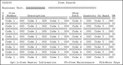
Figure 18-2 Field Definition portion of the Item Search screen

Description of "Figure 18-2 Field Definition portion of the Item Search screen"
| Field | Explanation |
|---|---|
| Dict Name | Identifies the four-byte data item name from the Data Dictionary.
This is the only required field for most data items, the rest will default. |
| Text | Describes the Dictionary Name.
VTX fields contain the soft coded description from the Data Dictionary that updates F9220 (Vocabulary Overrides). |
| Data Type | S – Numeric data items.
A – Alphanumeric. Blank – (w/decimal position blank in Size field)defaults to A. Blank– (w/decimal position defined in Size field) defaults to an S. All – JD Edwards World fields are defined as A. |
| Field Name | Identifies a screen field name.
|
| Row/Column | Two 3-digit fields that define the row and column location of field. |
| Field Use | How the data is to be used on the screen.
I – Input only O – Output only B – Both input and output H – Hidden field M – IBM Message field |
| Size | Two fields identify the length of the data item and for numeric fields, the decimal places.
|
| Text Form | For VTX fields, identifies the field from the Data Dictionary that is used for headings.
R – Row Description. C – Column Heading 1. D – Column Heading 2. |
| Dft Cursor | Starting cursor position on a data entry screen, Y or N. |
| Edited | Should the field be checked for error conditions, Y or N.
|
| Lower Case | To allow lowercase, Y or N. |
| Change | CHANGE keyword is in effect, Y or N. The indicator will be set on whenever the value in this field is changed. |
| OVERDTA | OVRDTA keyword is in effect, Y or N. Used with PUTOVR to override data that is in a field already on the screen. |
Note:
You should edit all input capable fields. (There will be a "Y" or "K" in the "Edited" field).| Field | Explanation |
|---|---|
| Duplicate | Duplicate the data. Only valid for a SFL format. Puts the DUP keyword in the screen/report DDS but the Program Generator does not generate any code to enable this. |
| OVRATR | OVRATR keyword is in effect, Y or N. Used with PUTOVR to override display attributes of a field on the screen. |
| Field Cond | Field Conditioning Indicators. Determines if the user can see the field or not. |
| Condition Indicators | To set a condition indicator on a field, enter a Y in the first blank to the right of the desired condition. You have the option of entering up to 3 indicators to be associated with the condition. Three spaces are provided to allow an N prior to the two digit indicator to create a negative condition. The allowed conditions are:
RI – Reverse Image HI – Highlight UL – Underline ND – Nondisplay BL – Blink PR – Protect PC – Place Cursor A blank or N will deactivate the condition. |
| Color | F8 toggles to display the color attributes for the field. The first blank to the right of each color controls the order that multiple colors will appear in the DDS (1-7). If multiple colors are defined, the first enabled color displays and the remaining colors are ignored. A blank or N disables the color. The color values default based on whether you selected JD Edwards World or SAA colors in QJDF. |
18.9 Accessing Fast Path Create for a New Screen
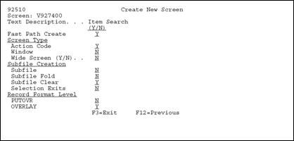
When you design the format for a new screen, you have the option to use Fast Path Create.
To access Fast Path Create for a new screen
-
Locate your screen and enter selection 10.
If SDA cannot find the existing DDS for your screen, the Create New Screen displays:
-
Press Enter and SDA begins the creation of your screen based on what you specified.
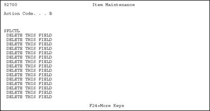
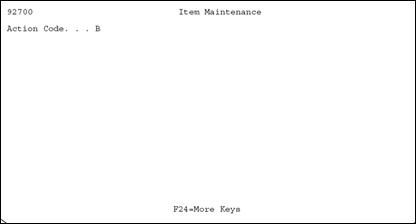
Figure 18-4 Example - Screen with Action Code and No Subfile
Description of "Figure 18-4 Example - Screen with Action Code and No Subfile"
Example - Screen with Action Code and Subfile
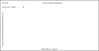
Figure 18-6 Example - Screen with Action Code, Subfile, and Selection Exits
Description of "Figure 18-6 Example - Screen with Action Code, Subfile, and Selection Exits"
18.10 Adding Fields without Using a Pick List
To add a Screen Text Field (VTX)
-
Place an asterisk (*) on the SDA design area where you want to place the screen text field.
Figure 18-7 Item Master Information screen
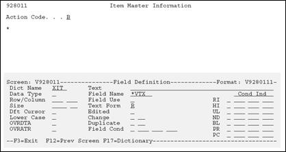
Description of "Figure 18-7 Item Master Information screen"
-
When the Field Definition window displays, do the following:
-
In the Dict Name field, enter the Data Dictionary item name.
-
In the Field Name field, specify *VTX.
The system assigns the next available VTX number.
-
-
Enter a value in the Text Form field to indicate whether the row description or a column heading from the Data Dictionary should be used as the text.
-
R - Row Description.
-
C - Column Heading 1.
-
D - Column Heading 2.
Note:
Text defaults from the Data Dictionary based upon the Text Form value. The default value is R for non-subfile formats. -
-
Enter a value in the Size field only if you want to override the default length of 16 for the Row Description that will be brought in.
Note:
You should start your fields in column two (unless selection exits exist). This allows you to place an asterisk to the left of the first field in column one.To add a Database Screen Field (VD)
-
Place an * on the SDA design area where you want the field to be placed.
Figure 18-8 Item Master Information screen
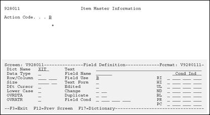
Description of "Figure 18-8 Item Master Information screen"
-
On the Field Definition window, enter the Data Dictionary item name in the Dict Name field.
-
Specify a field use:
-
The default for field use is O for output.
-
Editing indicators are not assigned for output fields.
-
-
The Data Type, Size, and Text default from the Data Dictionary.
To add a Screen Constant Field (VC0)
-
Place an * on the SDA design area where you want to place the description or constant field.
Figure 18-9 Item Master Information screen
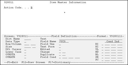
Description of "Figure 18-9 Item Master Information screen"
The Field Definition window displays .
-
On the Field Definition window, specify *VCO in the Field Name field.
The system assigns the next available VC0 number.
-
To override the default length of 30, enter a value in the size field.
18.11 Adding a Literal Field
JD Edwards World standard is that the only literal on a screen is the program ID in the top left corner.
Figure 18-10 Blank Item Master Information screen
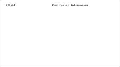
Description of "Figure 18-10 Blank Item Master Information screen"
18.12 Using the *BOTH and *ALL Features
The Field Definition window allows you to enter some special keywords in the Field Name field. Two of these special keywords are *BOTH and *ALL.
This feature provides for placement of multiple fields with a single entry.
18.12.1 Using *BOTH
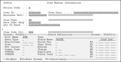
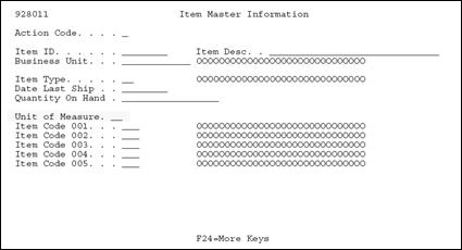
If you use the keyword *BOTH with a valid data dictionary item, screen design will place a VTX field and a screen (VD) field on the screen.
On Field Definition
Figure 18-11 Item Master Information screen
Description of "Figure 18-11 Item Master Information screen"
Type "*BOTH" in the Field Name
When you enter *BOTH, the following screen displays in the SDA design area for the Unit of Measure field:
Figure 18-12 Item Master Information screen
Description of "Figure 18-12 Item Master Information screen"
18.12.2 Using *ALL
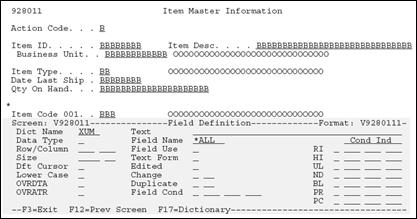
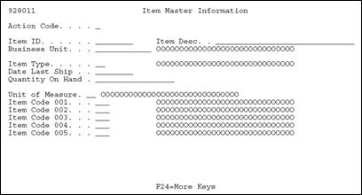
If you use the keyword *ALL with a valid Data Dictionary item, screen design places a VTX field, a screen (VD) field, and a VC0 field on the screen.
On the Field Definition window
Figure 18-13 Field Definition portion of the Item Master Information screen
Description of "Figure 18-13 Field Definition portion of the Item Master Information screen"
Type "*ALL" in the Field Name.
When you enter *ALL, the following screen displays in the SDA design area for the Unit of Measure field:
Figure 18-14 Unit of Measure Field on the Item Master Information screen
Description of "Figure 18-14 Unit of Measure Field on the Item Master Information screen"
The following are field defaults in SDA:
| Field | Explanation |
|---|---|
| VD - Screen Display field |
You can enter a B in the Field Use field to override the default and change it to both input and output.
If you enter B in the Field Use field, the Edited field defaults to Y. The Condition Indicators default to Y and the next available editing indicator is assigned to that field. |
| VTX - Screen Text field |
|
| VC0 - Screen Constant field |
|
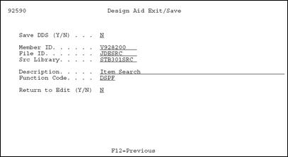
18.12.3 Understanding the SDA Exit/Save Function Key
F3 - Saves, exits, or does both from Screen Design Aid.
| Field | Explanation |
|---|---|
| Save DDS (Y/N) | Saves the DDS and updates or creates Vocabulary Overrides and Function Key definitions. |
| Member ID | The record of the Software Versions Repository member to be copied.
Screen-specific information Name of the screen. |
| File ID | Identifies the file that will contain the source code. |
| Src Library | Identifies the library where the source code resides. |
| Description | The description of a record in the Software Versions Repository file. The member description is consistent with the base member description. |
| Function Code | Should be DSPF for a Screen. |
| Return to Edit (Y/N) | EOJ or allows return to SDA. |
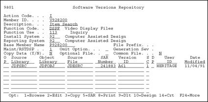
18.13 Compiling Your Screen
From the Software Versions Repository screen
Figure 18-16 Software Versions Repository screen
Description of "Figure 18-16 Software Versions Repository screen"
18.14 Screen Design Standards and Tips
18.14.1 Title
A screen title is limited to 30 characters and should match the Software Versions Repository (F9801). The title you enter in SDA updates the vocabulary overrides record for the screen. If you access the screen using a menu selection, the menu selection name overrides the screen title. If you access the screen using a selection option or function key, the vocabulary overrides title is used.
18.14.2 Line 24
You should document function keys on the right side of line 24 and you should document options on the left side. The following guidelines should also be followed:
-
List both the options and function keys in numeric order.
-
F24 should always appear and should say MORE KEYS or MORE.
-
F4 should always read MORE DETAIL or DETAIL.
-
Do not include standard exits of F3, F7, F22, Help, Rollup, Rolldown.
-
Line 24 should be in reverse image during an error condition. Line 24 is conditioned to appear in reverse image on screens based on indicator 93.
-
If you specify *SAME for the field "Error Text" for Line 24 in vocabulary overrides, then the text displayed is the same as the text specified for the normal Line 24.
18.14.3 Windows
Within a window, line 24 should include F3 and F24 when the window is initially displayed. When designing windows in SDA, fill in unused line space with literal fields to prevent data on the calling screen from showing through on the window. You can add the literal fields on the SDA screen as blanks with a single quote on each end or through the Field Definition window.
18.14.4 Default Cursor
You set the default cursor attribute to Action Code for the input field closest to the upper-left corner of the screen.
18.14.5 Fold Area
Keep the number of Fold Area lines to no more than two lines to avoid excessive use of the cursor keys when the Fold Area is open.
18.14.6 Description Fields
Define all description input fields to allow for uppercase and lowercase letters DDS keyword CHECK(LC). Use VC0 descriptions when a field's value has no obvious meaning and you can retrieve a description from a master file or user defined codes.
18.14.7 Alpha Fields
Because of the dynamic nature of international currency, you must define every field as alpha. The only exception is that you can define hidden fields as numeric. JD Edwards World scrubbing routines handle the two-way conversion between numeric data in the file and formatted alpha screen fields.
18.14.8 General Aesthetics
The following are things you might want to consider when designing screens. They are guidelines that will give your screens a more professional look.
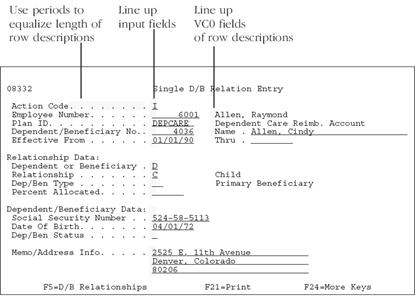
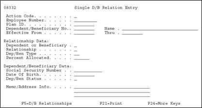
Line up fields vertically. This includes row descriptions, input fields, and description fields. Fields on the left side of the screen should be in column space 2 (column 1 is needed for the attribute byte).
When entering a descriptive heading to group related fields, use up to 40 characters for the description (or as long as space permits). Highlight the heading and end it with a colon. Underneath the heading, indent the group of fields one space to the right.
Figure 18-19 An Example of Grouped Fields
Description of "Figure 18-19 An Example of Grouped Fields"
Use the following as your standards when spacing different screen elements:
Figure 18-20 Standards for Spacing Screen Elements

Description of "Figure 18-20 Standards for Spacing Screen Elements"
-
Separate column headings with one space.
Figure 18-21 An Example of Separating Columns

Description of "Figure 18-21 An Example of Separating Columns"
-
End row descriptions with at least one period followed by a single space before you begin associated input fields.
-
Indent Fold Area fields one or more spaces to offset them from regular subfile.
-
Use two or more spaces to separate Fold Area data fields from row descriptions that follow on the same line. End Fold Area row descriptions with a colon instead of periods to aid legibility.
Figure 18-24 Ending Fold Area Row Descriptions

Description of "Figure 18-24 Ending Fold Area Row Descriptions"
-
Insert a blank line between header and subfile information.
Figure 18-25 Separating the Header and Subfile Rows

Description of "Figure 18-25 Separating the Header and Subfile Rows"
-
When possible, insert a blank line between the title and first field. Begin fields on line 3 unless you need to use the upper right corner of line 1 and 2.
18.15 Adding Screen Fields Using Pick List
From the SDA screen:
-
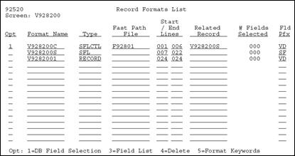
Access the Records Formats List using the F10 key.
-
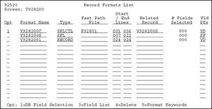
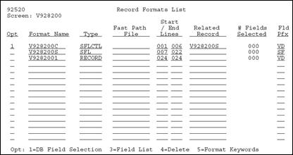
Press F10 to display the Record Formats List.
Use this screen to select database fields and maintain record formats, record types, fast path files, and record format keywords.
18.15.1 About Record Formats
Several Record Format Types are valid for screens. Currently, they include:
-
Present in all subfile screens. Contains all of the fields in the header or top portion of the screen, including the subfile column headings.
-
SFL - Subfile
Contains all the fields in the subfile portion of the screen, including the fold area (if applicable).
-
RECORD
Present in all screens. In subfile screens, contains VDL24 (line 24 text). In non-subfile screens, can contain all fields on the screen, including VDL24.
-
SFLMSG - Subfile Message
Displays error message text. JD Edwards World does not use this format because errors are handled through RPG programs.
18.16 Selecting Database Fields
There are two methods of selecting database fields for placement on the screen:
-
With Fast Path
-
With the File Selection List
| Method | Description |
|---|---|
| Fast Path | Type 1 next to the format on which you want to place the fields and enter a file name under the Fast Path File column. |
| File Selection List | Type 1 next to the format on which you want to place the fields but do not enter a file name.
Accesses a file selection screen where you can specify multiple files and libraries from which to select database fields. |
To select a database field using Fast Path
-
On the Record Formats List screen, enter a Fast Path File for the specified format.
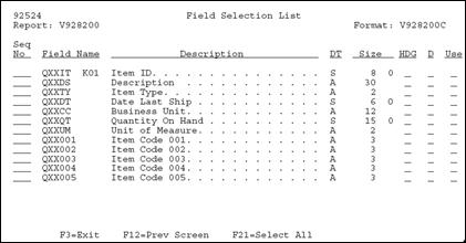
-
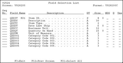
Press F21 to select all the fields for the file instead of selecting them individually.
Based on the record format for which you are using the Field Selection List, the following information is the default:
-
For a subfile control record format, the HDG field will default to R for the type of heading and the Use field will default to B for input/output.
-
For a subfile record format, the HDG field will default to D for the type of heading and the Use field will default to B for input/output.
-
For a non-subfile screen, the HDG field will default to R for the type of heading and the Use field will default to B for input/output.
-
For a report, the HDG field will default to D for the type of heading and the Use field will default to O for output.
-
To select database fields using the File Selection List
From the Record Formats List screen:
-
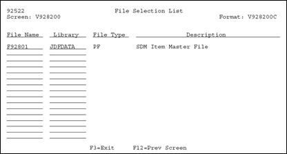
Enter the files from which you want to select fields.
Fields for files requested will be displayed through the Field Selection List screen.
-
Select fields using the same techniques as in the Fast Path method.
Note:
If you select a key field, that field is edited as the key of the screen. An edit indicator of 41 is assigned.18.17 Placing Fields on a Screen Using a Pick List
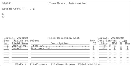
To place fields on a screen using a Pick List
On the Item Master Information screen
Figure 18-34 Item Master Information screen
Description of "Figure 18-34 Item Master Information screen"
-
Type either one or more ampersands (&) on the SDA screen where you want to place the fields from the pick list you created.
If you place more than one &, make sure that you allow room for all of the fields that are returned to the screen, so that you do not overlap fields.
-
On the Field Selection screen, verify the information that is on the screen (VTX field - HDG, 30-character description - D, and field Use - USE), as well as the order that they will be brought back (the sequence number), and row description length.
-
To add a Fold Area to a subfile, place an asterisk (*) or ampersand (&) on the second line in the subfile format of your screen. If you need a second line in the Fold Area, you can place an asterisk (*) or ampersand (&) on the third line of the subfile format. HDG should be "R" when adding fields to the fold.
18.18 Function Key Exits from Screen Design Aid
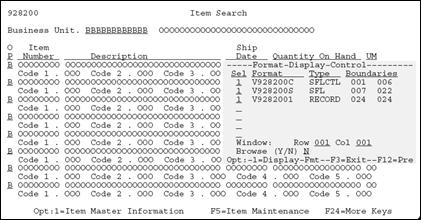
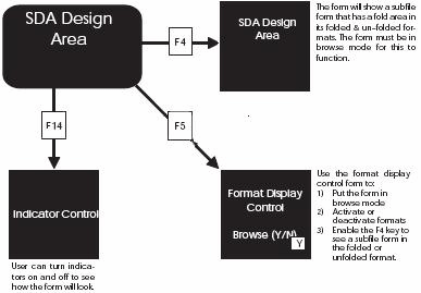
Example F5 - Format Display Control window.
Figure 18-35 Format Display Control portion of the Item Search screen
Description of "Figure 18-35 Format Display Control portion of the Item Search screen"
The following table provides an explanation of the fields in the Format Display Control window.
| Field | Explanation |
|---|---|
| Selection | Controls the display of record formats.
1 – Format is displayed. Blank – Format is not to be displayed. |
| Format | Lists the DDS format names for the screen screen.
All names begin with Screen name
|
| Type | Describes the format type. |
| Boundaries | Two 3-digit numbers that define the range (rows) for the DDS. |
| Window | Allows access to fields outside the boundaries. |
| Browse (Y/N) | Allows user to enable/disable the browse mode and view the screen as it would appear when executed.
|
| Function | Description |
|---|---|
| F4 | Provides the following: |
| F6 | This screen provides access to other repository services within JD Edwards World. |
| F8 | Provides the following: |
| F10 | Displays the Format Keyword Maintenance screen. |
Example F10 - Format Keyword Maintenance screen
Figure 18-36 Format Keyword Maintenance screen
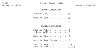
Description of "Figure 18-36 Format Keyword Maintenance screen"
| Field | Explanation |
|---|---|
| PUTOVR (Y/N) | The screen record format uses the PUTOVR keyword. Causes the screen to be erased and redisplayed when a window is displayed. |
| OVERLAY (Y/N) | The screen record format uses the OVERLAY keyword. Will not erase and redisplay screen when a window is displayed. Most JD Edwards World screens use OVERLAY. |
| Subfile Fold | Create a fold area in the subfile using SFLDROP and SFLFOLD keywords. |
| Type (A/F) | Further identifies subfile fold area:
A – Will lose modified data in the subfile when you press F4. F – Data is retained. |
| Subfile Clear | This option specifies if you want to use SFLCLR or SFLINZ. The default is SFLCLR. This option is ignored when designing non-subfile screens.
Y – means you want SFLCLR N – will give you SFLINZ |
| Subfile Next Change | Whether or not to use SFLNXTCHG (Y/N). Will require the user to correct any errors in the subfile before further execution of the program. |
| Subfile Page | Identifies the number of records on one subfile page, with the fold area open, if applicable.
|
| Subfile Size | Identifies the total number of records in the subfile that will be loaded in one program cycle.
|
| Function | Description |
|---|---|
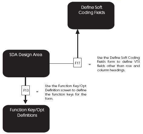
| F13 | Displays the Function Key/Opt Definition screen. |
Example F13 Function Key/Opt Definition screen
Figure 18-37 Function Key/Opt Definition screen
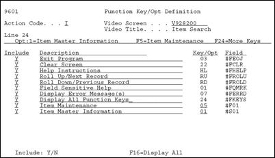
Description of "Figure 18-37 Function Key/Opt Definition screen"
| Field | Explanation |
|---|---|
| Action Code | One character field used to indicate the action that the user wants to take on the record requested.
Inquire on a record before you attempt to change it. |
| Screen Screen | The name of the screen or report record to be copied. All records for soft coding will be displayed. |
| Screen Title | The vocabulary overrides title used on screens and reports. On screens, the title is retrieved from the Menu file. If a record is not found, then the title is retrieved from the Vocabulary Overrides file. Report titles are retrieved from the DREAM Writer Version ID (F98301). |
| Include | Whether or not to include the function or option key on the screen. |
| Description | Describes the function or option exit.
Cannot exceed 40 characters. |
| Key/Opt | Identifies the function key number or option.
Special values:
|
| Field | Identifies the name of the function or option exit.
Values always begin with a # (pound sign). |
| Function | Description |
|---|---|
| F14 | Displays the Indicator Control portion of a simulated program execution screen.
|
Figure 18-38 Example F14 - Indicator Control Portion of a Simulated Program Execution screen
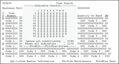
Description of "Figure 18-38 Example F14 - Indicator Control Portion of a Simulated Program Execution screen"
| Function | Description |
|---|---|
| F16 | Displays the List of Defined Fields screen. |
Figure 18-39 Example F16 - List of Defined Fields screen
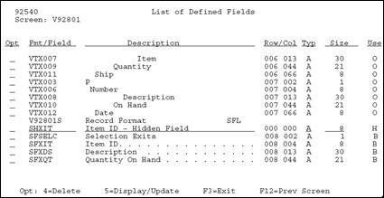
Description of "Figure 18-39 Example F16 - List of Defined Fields screen"
18.18.1 Hidden Fields
Used to store hidden field information.
To add a hidden field to a screen
-
Roll to the bottom blank line of the format that contains the field.
-
Choose option 5, Display/Update.
-
Enter the field with a prefix of SH, description, type, size, and press Enter.
This information should be the same as the associated database field.
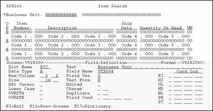
Option 5 - Select Field Definition
Figure 18-40 Option 5 - Select Field Definition screen
Description of "Figure 18-40 Option 5 - Select Field Definition screen"
Accesses the Field Definition screen, just as if you had entered an asterisk (*) for the field.
| Function | Description |
|---|---|
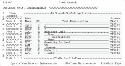
| F17 | Used to define soft coding (Vocabulary Override) fields.
Note: After changing the size of a VTX field, you should execute the Rebuild Vocabulary Override Field Lengths program (11/G9642). This displays the correct VTX field lengths in the Field Size field in Vocabulary Overrides. |
Figure 18-41 Example F17 - Define Soft Coding Fields screen
Description of "Figure 18-41 Example F17 - Define Soft Coding Fields screen"
| Function | Description |
|---|---|
| F19 | Used to window left.
Note: This function key is applicable only when designing wide screens (132 by 27 rows) on 80 column terminal. |
| F20 | Used to window right.
Note: This function key is applicable only when designing wide screens (132 by 27 rows) on 80 column terminal. |
18.19 Changing Subfile Boundaries
Be careful when changing the size of a subfile through SDA. Consider using these processes to make such changes easier and less confusing.
-
Change the starting line number for the subfile form at (VxxxxxS).
-
To return to SDA, press Enter.
-
To access the Record Formats List screen again, press F10.
-
Change the ending line number for the control format (VxxxxxC).
-
To return to SDA, press Enter.
-
Move or add headings.
You can reverse the above steps if you want to make the subfile larger. You must move the control format fields up before changing the starting line number for the subfile format.
-
Move headings.
-
To access the Record Formats List screen, press F10.
-
Change the ending line number for the control format (VxxxxxC).
-
To return to SDA, press Enter.
-
To access the Record Formats List screen again, press F10.
-
Change the starting line number for the subfile format (VxxxxxS).
-
To return to SDA, press Enter.
-
In SDA, press F10 to alter the format.
-
Enter 5 on the control format field.
-
Change subfile page size, as needed.
Note:
When you change the subfile, you must change the subfile page and subfile size to correctly reflect the size of the new subfile.18.20 Process Overview - Placing Selected Fields
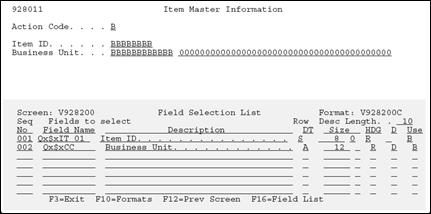
Once you have established your field pick list, use the ampersand (&) to specify where you want to locate the field.
Figure 18-42 Ampersand in the Item Master Information screen

Description of "Figure 18-42 Ampersand in the Item Master Information screen"
The ampersand (&) calls up the pick list in the Field Selection screen where you can order the fields and further define their specifications.
18.20.1 Options
The following options are available:
-
Override Row Description length
-
Resequence fields in list
-
Select headings (Row, Column headings) *VTX
-
Description Field (*VC0)
-
Usage (O=Output, B=Both Input and Output)
After you have sequenced the fields, they are retrieved from the file and placed on the design area.
Figure 18-44 Design Area Showing Field Selection List
Description of "Figure 18-44 Design Area Showing Field Selection List"
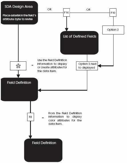
18.21 Process Overview - Revising the Field Definition
Figure 18-45 Process Flow to Revise the Field Definition
Description of "Figure 18-45 Process Flow to Revise the Field Definition"
18.22 Process Overview - Revising Vocabulary and Function Keys
Figure 18-46 Process Flow to Revise the Vocabulary and Function Keys
Description of "Figure 18-46 Process Flow to Revise the Vocabulary and Function Keys"
18.23 Function Keys for Screen and Display Format Control
Figure 18-47 Function Keys for Screen and Display Format Control
Description of "Figure 18-47 Function Keys for Screen and Display Format Control"
18.24 Summary of Screen Design Aid
-
d, *DEL
-
<<, >>
-
'xx...xx'
-
-, =
-
- -, =
-
* and &
You should not use the INSERT and DELETE keys while in SDA.
F7 restores a screen if you accidentally press Field Exit.
Standard prefixes:
-
VD, SF, SH
Special Fields:
-
*VTX, *VC0, *LITER, *DATE, *TIME
-
ACTION
-
VDL24
-
TTL@
Error indicators 40 to 79 are automatically assigned to VD and SF fields that are defined as input or input/output.
Update fields by using *.
You have two methods of adding fields to a screen:
-
* (non-pick list method)
-
& (pick list method)
You can pull in VTX, VC, and the screen database fields all at the same time for one database field.
You have two methods of selecting database fields:
-
Fast Path
-
Non-Fast Path - Accesses File Selection screen
If you are changing subfile boundaries, you should use the outlined processes to make this process easier.
You must save a screen at least once before updating vocabulary overrides or Function Key Definitions because the exit from SDA creates these records.
You add hidden fields from the List of Defined Fields screen, which you access by pressing F16 from SDA:
-
You add hidden fields one at a time.
-
You must enter a selection exit 5 to actually add the field.
