27 Work with Action Diagramming
This chapter contains these topics:
The Action Diagramming functionality allows you to produce a diagram which illustrates the different groupings of logic and the interrelationships of code within a program. The system generates the diagrams from the program source code. They provide easy access to more detailed information about the files, fields and programs in the code.
27.1 Building an Action Diagram
The Build Action Diagram program allows you to build the necessary cross reference items to produce the action diagram. Using DREAM Writer as the initial screen to the batch job, you can specify the programs for which you want to build an action diagram.
JD Edwards World includes sample Action Diagrams with the software but you must build the Action Diagram for all other programs. This is not an automatic function.
From Action Diagramming (G9363), choose Build Action Diagrams
27.2 Viewing an Action Diagram
When you view an action diagram, you are viewing a graphical representation of the code's hierarchy within the program and how different subsets of code relate to other subsets of code. You can view the code for a subroutine from the program or exit to facilities that show more detail for fields, files, and programs.
From Action Diagramming (G9363), choose Display Action Diagram
On Display Action Diagram, enter a program ID in the Program ID field to view an action diagram.
For example, enter P92801.
Figure 27-2 Display Action Diagram screen

Description of "Figure 27-2 Display Action Diagram screen"
The logic groups for the program display.
| Group | Description |
|---|---|
| Lvl/Sbr | Specifies the logic level and subroutine. |
| Program ID | The program name for the action diagram. |
| Scan | Allows the user to search for specific information. |
The use of colors, arrows, indentation, and connecting vertical lines indicates the hierarchy and relationships of the code within the program.
| Symbol | Description |
|---|---|
| ===> | Signals the beginning or ending of a loop. |
| ---> | Signals an IF or WHEN statement or their associated end statement. |
| Blank | Labels are in reverse image. |
27.2.1 Function Exits
Choose Display File Usage (F10) to view the files in the file specifications of the program.
Return to Previous Logic Level (F12)
Choose Return to Previous Logic Level (F12) to return to the logic level immediately prior to the one that currently displays.
Choose Scan Text Forward (F16) to enter a value in the Scan field and then scan forward through the code to locate the value.
Choose Scan Text Backward (F17) to enter a value in the Scan field and then scan backward through the code to locate the value.
Choose Skip to Start Group (F19) to skip to the beginning (start) of a section of code. The user places the cursor within the section of code and then chooses Skip to Start Group to go to the beginning of that section of code.
Choose Skip to End Group (F20) to skip to the end of a section of code. The user places the cursor within the section of code and then chooses Skip to End Group to go to the end of that section of code.
Choose Print Action Diagram (F21) to obtain a printout of the action diagram.
Choose Program Flowchart (F23) to view and print, or view, or print a flowchart which illustrates the interaction of files and processes that relate to a single program. You can continue to view lower levels of detail as well.
27.2.2 Cursor Sensitive Function Exits
To access information that relates to fields, files, and programs appearing in the program code, you can use cursor sensitive function exits to access this information by placing the cursor at the beginning of the field, file, or program.
Software Versions Repository (F13)
Choose Software Versions Repository (F13) to access the Software Versions Repository.
Choose File Field Description (F14) to display the File Field Description screen.
Choose Data Cross Reference (F15) to access the cross reference program.
Choose Data Dictionary (F18) to access the Data Dictionary program.
The following chart indicates which function exits access relevant information for the different elements.
| Element | Function Exit | Description |
|---|---|---|
| Fields | Data Cross Reference (F15) | Displays all the programs that use the data item. |
| Data Dictionary (F18 | Displays the Data Dictionary definition for the data item. | |
| Files | Display File Usage (F10) | Displays the files within the program. |
| Software Versions Repository (F13) | Displays the Software Versions Repository record for the file. | |
| File Field Description (F14) | Displays the File Field Descriptions for the file. | |
| Data Cross Reference (F15) | Displays all the programs that use the file. | |
| Programs | Software Versions Repository (F13) | Displays the Software Versions Repository record for the program. |
| Data Cross Reference (F15) | Displays all the programs that launch the program. |
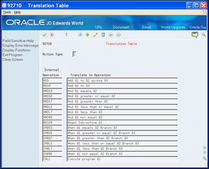
27.3 Accessing the Logic Translation Feature
The Logic Translation feature allows you to view how the Action Diagram feature translates the RPG code of a program into an Action Diagram.
To access the logic translation feature
From Action Diagramming (G9363), choose Translation Table
The system displays the RPG operation in the first column and how it translates that operation within an action diagram in the second column.