| Skip Navigation Links | |
| Exit Print View | |

|
Securing the Network in Oracle Solaris 11.1 Oracle Solaris 11.1 Information Library |
| Skip Navigation Links | |
| Exit Print View | |

|
Securing the Network in Oracle Solaris 11.1 Oracle Solaris 11.1 Information Library |
1. Using Link Protection in Virtualized Environments
2. Tuning Your Network (Tasks)
3. Web Servers and the Secure Sockets Layer Protocol
4. IP Filter in Oracle Solaris (Overview)
6. IP Security Architecture (Overview)
How to Secure Traffic Between Two Systems With IPsec
How to Use IPsec to Protect a Web Server From Nonweb Traffic
Examples of Protecting a VPN With IPsec by Using Tunnel Mode
Description of the Network Topology for the IPsec Tasks to Protect a VPN
How to Manually Create IPsec Keys
How to Configure a Role for Network Security
How to Manage IPsec and IKE Services
How to Verify That Packets Are Protected With IPsec
8. IP Security Architecture (Reference)
9. Internet Key Exchange (Overview)
Oracle Solaris can configure a VPN that is protected by IPsec. Tunnels can be created in tunnel mode or in transport mode. For a discussion, see Transport and Tunnel Modes in IPsec. The examples and procedures in this section use IPv4 addresses, but the examples and procedures apply to IPv6 VPNs as well. For a short discussion, see Protecting Traffic With IPsec.
For examples of IPsec policies for tunnels in tunnel mode, see Examples of Protecting a VPN With IPsec by Using Tunnel Mode.
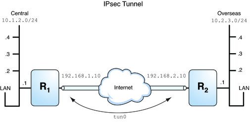
Figure 7-1 Tunnel Protected by IPsec

The following examples assume that the tunnel is configured for all subnets of the LANs:
## Tunnel configuration ##
# Tunnel name is tun0
# Intranet point for the source is 10.1.2.1
# Intranet point for the destination is 10.2.3.1
# Tunnel source is 192.168.1.10
# Tunnel destination is 192.168.2.10
# Tunnel name address object is tun0/to-central
# Tunnel name address object is tun0/to-overseas
Example 7-2 Creating a Tunnel That All Subnets Can Use
In this example, all traffic from the local LANs of the Central LAN in Figure 7-1 can be tunneled through Router 1 to Router 2, and then delivered to all local LANs of the Overseas LAN. The traffic is encrypted with AES.
## IPsec policy ##
{tunnel tun0 negotiate tunnel}
 ipsec {encr_algs aes encr_auth_algs sha512 sa shared}
Example 7-3 Creating a Tunnel That Connects Two Subnets Only
In this example, only traffic between subnet 10.1.2.0/24 of the Central LAN and subnet 10.2.3.0/24 of the Overseas LAN is tunneled and encrypted. In the absence of other IPsec policies for Central, if the Central LAN attempts to route any traffic for other LANs over this tunnel, the traffic is dropped at Router 1.
## IPsec policy ##
{tunnel tun0 negotiate tunnel laddr 10.1.2.0/24 raddr 10.2.3.0/24}
 ipsec {encr_algs aes encr_auth_algs sha512 shared}
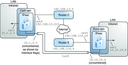
The procedures that follow this section assume the following setup. For a depiction of the network, see Figure 7-2.
Each system is using an IPv4 address space.
Each system has two interfaces. The net0 interface connects to the Internet. In this example, Internet IP addresses begin with 192.168. The net1 interface connects to the company's LAN, its intranet. In this example, intranet IP addresses begin with the number 10.
Each system requires ESP authentication with the SHA-2 algorithm. In this example, the SHA-2 algorithm requires a 512-bit key.
Each system requires ESP encryption with the AES algorithm. The AES algorithm uses a 128-bit or 256-bit key.
Each system can connect to a router that has direct access to the Internet.
Each system uses shared security associations.
Figure 7-2 Sample VPN Between Offices Connected Across the Internet

As the preceding illustration shows, the procedures use the following configuration parameters.
|
For information about tunnel names, see Tunnel Configuration and Administration With the dladm Command in Configuring and Administering Oracle Solaris 11.1 Networks. For information about address objects, see How to Configure an IP Interface in Connecting Systems Using Fixed Network Configuration in Oracle Solaris 11.1 and the ipadm(1M) man page.
In tunnel mode, the inner IP packet determines the IPsec policy that protects its contents.
This procedure extends the procedure How to Secure Traffic Between Two Systems With IPsec. The setup is described in Description of the Network Topology for the IPsec Tasks to Protect a VPN.
For a fuller description of the reasons for running particular commands, see the corresponding steps in How to Secure Traffic Between Two Systems With IPsec.
Note - Perform the steps in this procedure on both systems.
In addition to connecting two systems, you are connecting two intranets that connect to these two systems. The systems in this procedure function as gateways.
Note - To use IPsec in tunnel mode with labels on a Trusted Extensions system, see the extension of this procedure in How to Configure a Tunnel Across an Untrusted Network in Trusted Extensions Configuration and Administration.
Before You Begin
You must be in the global zone to configure IPsec policy for the system or for a shared-IP zone. For an exclusive-IP zone, you configure IPsec policy in the non-global zone.
To run configuration commands, you must become an administrator who is assigned the Network Management and Network IPsec Management rights profiles. To edit system files, you must assume the root role. For more information, see How to Use Your Assigned Administrative Rights in Oracle Solaris 11.1 Administration: Security Services.
If you log in remotely, use the ssh command for a secure remote login. For an example, see Example 7-1.
# routeadm -d ipv4-routing
# ipadm set-prop -p forwarding=off ipv4
# routeadm -u
Turning off IP forwarding prevents packets from being forwarded from one network to another network through this system. For a description of the routeadm command, see the routeadm(1M) man page.
# ipadm set-prop -p hostmodel=strong ipv4
Turning on IP strict multihoming requires that packets for one of the system's destination addresses arrive at the correct destination address.
When the hostmodel parameter is set to strong, packets that arrive on a particular interface must be addressed to one of the local IP addresses of that interface. All other packets, even packets that are addressed to other local addresses of the system, are dropped.
Verify that loopback mounts and the ssh service are running.
# svcs | grep network
online         Aug_02   svc:/network/loopback:default
…
online         Aug_09   svc:/network/ssh:default
Edit the /etc/inet/ipsecinit.conf file to add the IPsec policy for the VPN. For additional examples, see Examples of Protecting a VPN With IPsec by Using Tunnel Mode.
In this policy, IPsec protection is not required between systems on the local LAN and the internal IP address of the gateway, so a bypass statement is added.
# LAN traffic to and from this host can bypass IPsec.
{laddr 10.16.16.6 dir both} bypass {}

# WAN traffic uses ESP with AES and SHA-2.
{tunnel tun0 negotiate tunnel}
ipsec {encr_algs aes encr_auth_algs sha512 sa shared}# LAN traffic to and from this host can bypass IPsec.
{laddr 10.1.3.3 dir both} bypass {}
# WAN traffic uses ESP with AES and SHA-2.
{tunnel tun0 negotiate tunnel}
ipsec {encr_algs aes encr_auth_algs sha512 sa shared}Configure IKE by following one of the configuration procedures in Configuring IKE (Task Map). For the syntax of the IKE configuration file, see the ike.config(4) man page.
# ipsecconf -f -c /etc/inet/ipsecinit.conf
Fix any errors, verify the syntax of the file, and continue.
# svcadm refresh svc:/network/ipsec/policy:default
IPsec policy is enabled by default, so you refresh it. If you have disabled IPsec policy, enable it.
# svcadm enable svc:/network/ipsec/policy:default
The following commands configure the internal and external interfaces, create the tun0 tunnel, and assign IP addresses to the tunnel.
If the interface net1 does not already exist, the first command creates it.
# ipadm create-addr -T static -a local=10.1.3.3 net1/inside
# dladm create-iptun -T ipv4 -a local=10.1.3.3,remote=10.16.16.6 tun0
# ipadm create-addr -T static \
-a local=192.168.13.213,remote=192.168.116.16 tun0/v4tunaddr
# ipadm create-addr -T static -a local=10.16.16.6 net1/inside
# dladm create-iptun -T ipv4 -a local=10.16.16.6,remote=10.1.3.3 tun0
# ipadm create-addr -T static \
-a local=192.168.116.16,remote=192.168.13.213 tun0/v4tunaddr
Note - The -T option to the ipadm command specifies the type of address to create. The -T option to the dladm command specifies the tunnel.
For information about these commands, see the dladm(1M) and ipadm(1M) man pages, and How to Configure an IP Interface in Connecting Systems Using Fixed Network Configuration in Oracle Solaris 11.1. For information about customized names, see Network Devices and Datalink Names in Oracle Solaris Administration: Network Interfaces and Network Virtualization.
# ipadm set-ifprop -m ipv4 -p forwarding=on net1
# ipadm set-ifprop -m ipv4 -p forwarding=off net0
IP forwarding means that packets that arrive from somewhere else can be forwarded. IP forwarding also means that packets that leave this interface might have originated somewhere else. To successfully forward a packet, both the receiving interface and the transmitting interface must have IP forwarding turned on.
Because the net1 interface is inside the intranet, IP forwarding must be turned on for net1. Because tun0 connects the two systems through the Internet, IP forwarding must remain on for tun0. The net0 interface has its IP forwarding turned off to prevent an outside adversary from injecting packets into the protected intranet. The outside refers to the Internet.
# ipadm set-addrprop -p private=on net0
Even if net0 has IP forwarding turned off, a routing protocol implementation might still advertise the interface. For example, the in.routed protocol might still advertise that net0 is available to forward packets to its peers inside the intranet. By setting the interface's private flag, these advertisements are prevented.
# svcadm restart svc:/network/initial:default
The default route must be a router with direct access to the Internet.
# route -p add net default 192.168.13.5
# route -p add net default 192.168.116.4
Even though the net0 interface is not part of the intranet, net0 does need to reach across the Internet to its peer system. To find its peer, net0 needs information about Internet routing. The VPN system appears to be a host, rather than a router, to the rest of the Internet. Therefore, you can use a default router or run the router discovery protocol to find a peer system. For more information, see the route(1M) and in.routed(1M) man pages.