2 Working with the Oracle ADF Model Layer
The model layer represents the data values related to the current page.
This section contains the following topics:
2.1 Creating the JPA Model Project
If you did not create the JPA project when you created your ADF Application, you can create one using the New Gallery.
To create the JPA project:
- From the main menu, select File > New > Other. From the New Gallery, open the JPA node and select JPA Project.
- In the New JPA Project wizard, enter the following details:
- Project name
- Project location (
<user_home>/workspace by default)
- Target runtime
- JPA version (If you have installed JPA 2.0, the version defaults to
2.0)
- Configuration. Note: You can modify the default configuration to add the Oracle WebLogic EJB Extensions facet or the Oracle WebLogic Utility Module Extensions facet. These facets cannot be added together. The benefit of using the WLS Extensions facet during project creation is that you can take advantage of the EclipseLink/TopLink shared libraries that ship with Oracle WebLogic Server. If you do not select a WLS Extensions facet, you will need to manually configure your JPA runtime.
- EAR Membership. Select an EAR file to add the project to. Not selecting an EAR will not prevent the project from being added to the current ADF EAR project.
- Working sets
- Once you have added details in the JPA Project page of the New JPA Project Wizard, click Next.
- On the Java page, specify the source folders on build path and the default output folder, and click Next.
- On the JPA Facet page, specify the Platform, JPA Implementation, and database connection settings, and click Finish.
2.2 Creating JPA Entities from Tables
To create JPA Entities from Tables:
- Right-click your JPA project, and in the context menu, select JPA Tools > Generate Entities from Tables.
- On the Generate Custom Entities wizard - Select Tables page, select a database connection from the Connection dropdown list, or click the New Connections button to add a connection.
- On the Generate Custom Entities wizard - Select Tables page, select a database schema from the Schema dropdown list, and select the tables you want to generate entities from in the Tables area. Then click Next.
- On the Table Associations page, review and optionally edit the table associations. Then click Next.
- On the Customize Default Entity Generation page, optionally customize aspects of entities that will be generated by default from database tables. You must specify a Java package.
- On the Customize Individual Entities page, optionally customize individual entities. Then click Finish.
- In the Project Explorer, expand the src folder in your JPA project to see the JPA entities that have been created.
2.3 Working with Session Beans
Session beans implement business logic. A session bean instance serves one client at a time.
2.3.1 Generating a Session Bean on Selected JPA Entities
To generate a session bean on selected JPA entities:
- Right-click your JPA project to open the context menu.
- In the context menu, select New > Session Bean (EJB 3.x) from JPA Entities.
- On the Session Bean (EJB 3.x) page of the Create EJB 3.x Session Bean from JPA Entities wizard, specify a Java package and a class name. Then click Next.
- On the Select Entities page, indicate which entities to access via the generated session bean. Then click Finish.
- You can view the generated session bean in the Project Explorer.
2.3.2 Generating a JSF Managed Bean
You can generate a JSF Managed Bean which is a wrapper on a session bean.
To generate a JSF Managed Bean:
- Right-click the session bean in the Project Explorer to open the context menu.
- In the context menu, select New > Data Model Components > Generate JSF Managed Bean.
- On the Managed Bean page of the Create Managed Bean wizard, specify the Java package and the Session bean to wrap. Then click Finish.
- View the generated JSF Managed Bean in the Project Explorer.
Notes:
- While regeneration is available for EJBs, it is currently not supported for a Managed Bean. The Create Managed Bean wizard will fail if the class already exists.
- OEPE uses the
@generated annotation to determine what can be overwritten when regenerating the EJB. If you customize one of the generated methods, persist for example, you will need to remove the @generated label from the method before regenerating an EJB.
2.3.3 Generating a Session Bean and a JSF Managed Bean using the Data Components Model Wizard
You can generate a Session Bean facade on selected entities and generate a JSF Managed Bean to wrap the services in the session facade using the Data Components Model WIzard.
To generate a Session Bean and a JSF Managed Bean using the Data Components Model Wizard:
- Open the New Gallery by selecting File > New > Other.
- Expand Application Development Framework, and double-click Data Model Components.
- On the Session Bean (EJB 3.x) page of the Create Data Model Components wizard, specify the Java package and class name for the session bean. Then click Next.
- On the Select Entities page, indicate which entities to access via the generated session bean, then click Next.
- On the Data Object page, select JSF Managed Bean or ADF Data Control as the Data object type. Then specify name and location details for the Managed Bean and click Finish. For more information on ADF Model Data Binding see Working with ADF Model Data Binding.
- In the Project Explorer, view the generated session bean facade in the JPA project and the JSF Managed Bean in the web project.
2.3.4 Editing a Session Bean
To edit the session bean facade:
- Right-click the session bean to open the context menu.
- In the context menu, select Data Model Components > Edit Session Bean Facade.
- On the Select Entities page, indicate which entities you want to add to or remove from the session bean facade.
For more information on EJB session beans, see the Understanding
Enterprise JavaBeans chapter in the Oracle Fusion Middleware
Programming Enterprise JavaBeans for Oracle WebLogic Server.
2.4 Working with ADF Model Data Binding
This section describes how to create ADF model data controls for EJB session beans and POJOs (plain, old Java objects) and how to use the Data Palette to create databound UI components on web pages.
This section contains the following topics:
2.4.1 Introduction to ADF Model Data Binding
ADF Model implements two concepts that enable the decoupling of the user interface technology from the business service implementation: data controls and bindings. Data controls abstract the implementation technology by using standard metadata interfaces to describe the bean's operations and data collections, including information about the properties, methods, and types involved. In OEPE, you can view this information in the Data Palette, and create databound HTML elements for JSP pages by dragging and dropping data control artifacts from the Data Palette onto the editor for a page. OEPE automatically creates the metadata that describes the bindings from the page to the services. At runtime, the ADF Model layer reads
the metadata information from the appropriate XML files for both the data controls and the bindings, and then implements the two-way connection between your user interface and your services.
Declarative bindings abstract the details of accessing data from data collections in a data control and of invoking its operations. There are three basic kinds of declarative binding objects:
- Executable bindings: Include iterator bindings, which simplify the building of user interfaces that allow scrolling and paging through collections of data and drilling-down from summary to detail information. Executable bindings also include bindings that allow searching and nesting a series of pages within another page.
- Value bindings: Used by UI components that display data. Value bindings range from the most basic variety that work with a simple text field to more sophisticated list and tree bindings that support the additional needs of list, table, and tree UI controls.
- Action bindings: Used by UI command components like hyperlinks or buttons to invoke built-in or custom operations on data collections or a data control without writing code.
The following figure shows how bindings connect UI components to data control collections and methods.
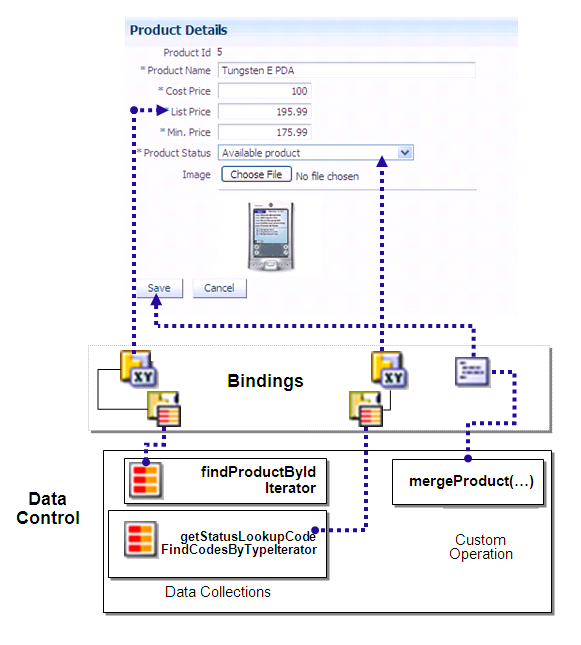
The group of bindings supporting the UI components on a page are described in a page-specific XML file called the page definition file. The ADF Model layer uses this file at runtime to instantiate the page's bindings. These bindings are held in a request-scoped map called the binding container.
2.4.2 Creating ADF Data Controls
Once you have your application's services in place, you can use OEPE to create data controls that provide the information needed to declaratively bind UI components to those services. In an ADF application, you can create a data control for the session bean or POJO, and that data control will contain representation of all data on the bean. The data control consists of a number of XML metadata files that define the capabilities of the service that the bindings can work with at runtime.
To create a data control from the Project Explorer:
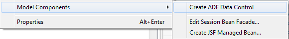
- In the Project Explorer, right-click the session bean or POJO for which you want to create a data control.
- From the context menu, select Model Components > Create ADF Data Control, as shown in the following figure.
Alternatively, you can also create a data control from the New Gallery.
To create a data control from the New Gallery:
- Right-click your model project and select New > Other from the context menu.
- In the New gallery, Oracle > Application Development Framework > ADF Data Control.
- On the Bean Class page, select project [Project] and the bean [Bean Class] from which to create the data control. Note: The Project dropdown list contains all eligible projects in the workspace.
- Preview and confirm the project changes on the Summary page and click Finish.
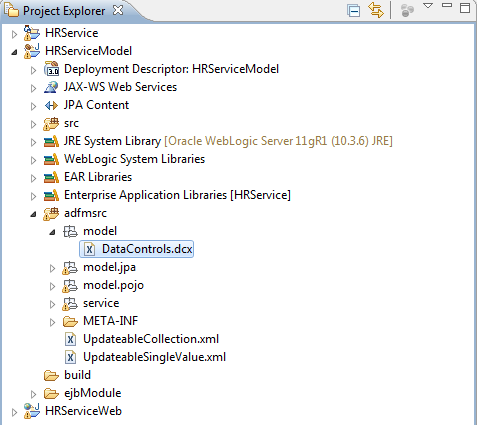
The metadata file datacontrols.dcx is created in the adfmsrc > model node of your Model project, as shown in the following figure. When you create a data control based on an EJB session bean, the data control contains a representation of all the methods exposed on the bean, as well as underlying entity beans, and the methods and properties exposed on those.
For a description of Oracle ADF Data Bindings metadata files and links to more information, see appendix A.1 Oracle ADF Data Binding Files.
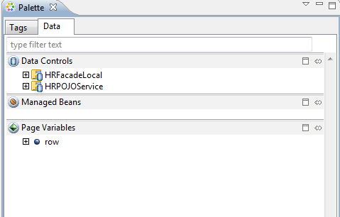
With a web page in focus, you can open the Data section of the Palette to view and drag-and-drop data controls, JSF Managed Beans, and page variables on to the page, as shown in the following figure.
For more information about ADF data controls, see the Exposing Services with ADF Data Controls section of the Oracle Fusion Middleware Java EE Developer's Guide for Oracle Application Development Framework.
2.4.3 Using the Data Palette to Create UI Components
OEPE provides you with a predefined set of UI components from which to choose for each data control item you drop.
To use the Data Palette to create UI components:
- Select an item in the Data Controls panel and drag it onto the editor for your page. You can also drag it and drop it from the data palette to the Outline view.
- From the ensuing context menu, select a UI component. When you drag an item from the Data palette and drop it on a page or task flow, OEPE displays a context menu of all the default UI components available. The UI components currently supported are: Form, Graph, Navigation, Single Selection, and Table.
Depending on the component you select from the context menu, OEPE displays a dialog that enables you to define how you want the component to look.
For example, if you select Form > ADF Form, the Create Form dialog is opened, as shown in the following figure. You can specify if you want it to be a Read-Only Form. Additionally, you can edit the Fields table to change the Display Label, Value Binding, and Component to Use elements. Additionally, you can add or delete value bindings, and specify if you want to include navigation controls and a submit button.
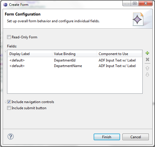
The resulting code appears in the source editor for your page.
- You can click the Edit Component Definition toolbar button
on the Properties window to edit the properties of your UI component.
Note: This feature is currently supported only for ADF Table and ADF DVT Graph components.
For more information about using the data palette, see the "Using the Data Controls Panel" section of the Oracle� Fusion Middleware Java EE Developer's Guide for Oracle Application Development Framework.
To run the ADF page containing your newly added component, right-click the page in the Project Explorer and select Run As > Run on Server. For more information, see Deploying an Oracle ADF Application.
Note: When running an ADF page from within OEPE, graph components may render inconsistently in the Eclipse browser. Using an external browser is recommended for best results.
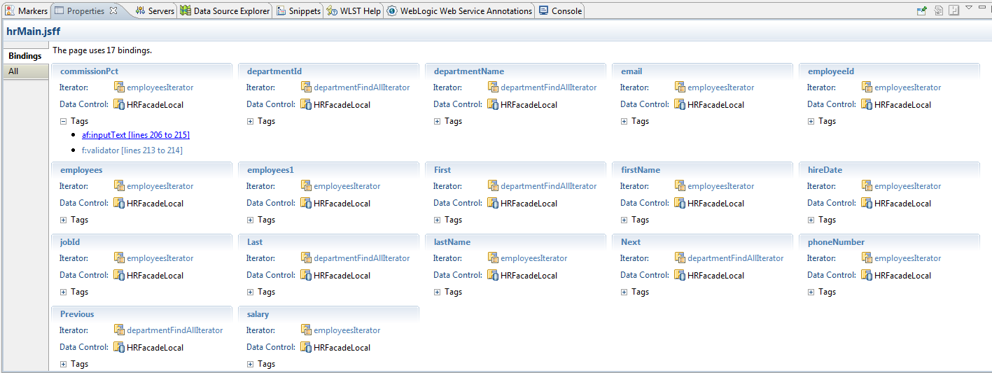
2.4.4 Using the Bindings Tab in the Properties Window
You can view the bindings associated with a page in the Bindings tab of the Properties window. The tab provides contextual bindings information based on the tag currently in focus in the editor, as shown in the following figure. The Bindings tab provides the following features:
- If you place the cursor in the
jsp:root tag of the page, the Bindings tab provides an overview of all the bindings used in the page.
- Each binding is listed along with its iterator and associated data control, in addition to the tags it is used in.
- Click on the binding id or iterator to open the item in the page definition editor.
- Click on a tag to highlight that portion of the source code in the web page editor.
2.4.5 Working with Page Definition Files
Page definition files define the binding objects that populate the data in UI components at runtime. For every page that has ADF bindings, there must be a corresponding page definition file that defines the binding objects used by that page. Page definition files provide design time access to all the ADF bindings. At runtime, the binding objects defined by a page definition file are instantiated in a binding container, which is the runtime instance of the page definition file.
When you drag and drop an item from the Data Palette to to the page, OEPE automatically creates a page definition file for that page and adds definitions for each binding object referenced by the component. For each subsequent databound component you add to the page, OEPE automatically adds the necessary binding object definitions to the page definition file. By default, the page definition files are located in the view.PageDefs package in the adfmsrc directory of the web project.
OEPE names the page definition files using the following convention:
pageNamePageDef.xml
where pageName is the name of the JSP page. For example, if the JSF page is named home.jsp, the default page definition file name is homePageDef.xml.
2.4.5.1 Opening a Page Definition File in the Page Definition Editor
You can open a page definition file in the page definition editor using any of the following ways:
- Right-click the page in the Project Explorer and select Open Page Definition. If the page does not have an associated page definition file, OEPE asks if you want to create it.
- With a page active in the editor, from the main menu, select Navigate > Go To > Page Definition.
- In the Bindings tab of the Properties view, click on a binding id to open it in the page definition editor.
- If the page definition file already exists, you can double-click it in the Project Explorer.
2.4.5.2 Understanding the Page Definition Editor
The page definition editor allows you to view and configure bindings. It consists of the following sections:
- Outline: Shows three different types of objects: bindings, executables, and the data controls in use. You can also add a new binding or executable using the New button (green plus icon). When you click an item in the Outline section, its corresponding details are shown in the right pane in the Binding (for bindings) and Iterator Binding (for executables) section.
- Binding: Displays information about the binding currently selected in the Outline section.
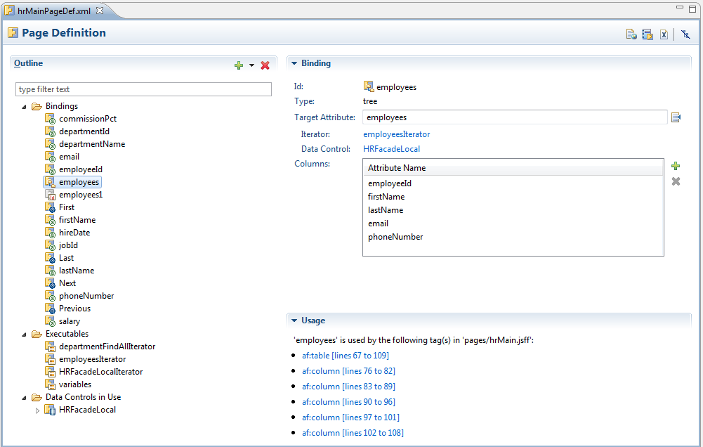
- Executable: Displays information about the executable currently selected in the Outline section.
- Iterator Binding: Displays information about the currently selected iterator in the Outline section.
- Usage: Displays usage information. For a binding, it displays the tags that use it. For an executable, it displays the bindings that use it. For a data control, the bindings and executables that use it are displayed.
- Bindings Summary or Executable Summary, Validation Details, Usage Details: These sections display summary information when the parent Bindings or Executables folder is selected in the Outline section.
- Data Control: Displays the Id and Type of the currently selected data control.
- Data Control Child: Displays the Id and Type of the currently selected Data Control child element.
The toolbar icons on the top right corner of the page definition editor are:
 Open file_name: Click to open the associated JSP page, where file_name is the name of the file.
  Open 'adfmsrc/view/DataBindings.cpx': Click to open the DataBindings.cpx file.
 Open this page definition using the XML editor
 Hide Outline: Click to hide the Outline section.
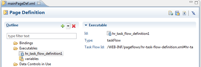
The page definition editor is tolerant of artifacts that are not supported.
For example, in the screenshot below, the editor recognizes the taskflow executable
even though the artifact is not supported.
If a page definition file is modified outside of the page definition editor, the editor will inform you via the External Changes Detected dialog. The contents of the file are then reloaded. Additionally, the editor also supports Forward and Back navigation from the Eclipse IDE. You can navigate previous selections using either the left and right arrows on the Eclipse toolbar or the main menu items Navigate > Back and Navigate > Forward.
2.4.5.3 Understanding Bindings and Executables
Declarative bindings abstract the details of accessing data from data collections in a data control and of invoking its operations.
Bindings
There are three types of Bindings binding objects used to bind UI components to objects on the data control:
- Value: Displays data in UI components by referencing an iterator binding. Each discrete UI component on a page that will display data from the data control is bound to a value binding object. Value binding objects include:
- Attribute Values: Binds text fields to a specific attribute in an object (also referred to as an attribute binding object.)
- List: Binds the list items to all values of an attribute in a data collection.
- Tree: Binds an entire table to a data collection and can also bind the root node of a tree to a data collection.
- Button (boolean): Binds a checkbox to a boolean value for an attribute.
- Method Action: Binds command components, such as buttons or links, to custom methods on the data control. A method action binding object encapsulates the details about how to invoke a method and what parameters (if any) the method is expecting.
- Action: Binds command components, such as buttons or links, to built-in data control operations (such as, Commit or Rollback) or to built-in collection-level operations (such as, Create, Delete, Next, or Previous).
- Task Flow: A binding used to encapsulate a reusable portion or region of an application. You can isolate a small, specific piece of application functionality as a region that can be reused throughout the application. Task flow binding enables you to extract, parameterize, and package reusable content so that it can be added to other pages. task flows can be reused wherever needed, which means they are not dependent on a parent page.
Executables
There are five types of supported executable binding objects:
- Iterator: Binds to an iterator that iterates over view object collections.
There is one iterator binding for each collection used on the page. All of the
value bindings on the page must refer to an iterator binding in order for the
component values to be populated with data at runtime.
When you drop a collection or an attribute of a collection on the page, an
iterator binding is automatically added as an executable. Iterator binding
objects bind to an underlying ADF RowSetIterator object, which
manages the current object and current range information. The iterator binding
exposes the current object and range state to the other binding objects used
by the page. The iterator range represents the current set of objects to be
displayed on the page. The maximum number of objects in the current range is
defined in the rangeSize attribute of the iterator. For example,
if a collection in the data control contains products and the iterator range
size is 25, the first 25 products in the collection are displayed on the page.
If the user scrolls down, the next set of 25 is displayed, and so on. If the
user scrolls up, the previous set of 25 is displayed. If your view object uses
range paging, then you can configure the iterator binding to return a set of
ranges at one time.
Note: If you have two pages each with an iterator binding
bound to the iterator on the same view object (which you will if you drop the
same collection, for example, on two different pages), then you should ensure
that the rangeSize attribute is the same for both pages' iterator
bindings. If not, the page with a smaller range size may cause the iterator
to re-execute, causing unexpected results on the other page.
- Method Iterator: Binds to an iterator that iterates over the collections returned
by custom methods in the data control.
A method iterator binding is always related to a method action binding object.
The method action binding encapsulates the details about how to invoke the
method and what parameters (if any) the method is expecting. The method action
binding is itself bound to the method iterator, which provides the data.
You will see method iterator executable binding objects only if you drop a
method return collection or an attribute of a method return collection from
a custom method on the data control.
- Variable Iterator: Binds to an iterator that exposes all the variables in the
binding container to the other bindings. While there is an iterator binding for
each collection, there is only one variable iterator binding for all variables
used on the page. (The variable iterator is like an iterator pointing to a collection
that contains only one data object whose attributes are the binding container
variables.)
Page variables are local to the binding container and exist only while the
binding container object exists. When you use a data control method (or an
operation) that requires a parameter that is to be collected from the page,
OEPE automatically defines a variable for the parameter in the page definition
file. Attribute bindings can reference the page variables.
- Accessor Iterator: Iterates over detail collections returned by accessor methods.
Accessor iterators are always related to a master iterator, which is a method
iterator. The accessor iterator returns the detail objects related to the current
object in the master (or method) iterator.
- Invoke Action: Binds to a method that invokes the operations or methods defined
in action or method action bindings during any phase of the page lifecycle.
2.4.5.4 Adding Bindings and Executables
Bindings are added on the Page Definition page, which can be accessed by right-clicking your page in the Project Explorer, and choosing Open Page Definition. For information on tree bindings see Working with Tree Bindings
To add a new binding:
- In the Outline section, click the New icon and then select Binding.
- In the New Binding dialog, select the type of the new binding, for example,
list, and enter the Id. Then click OK. The binding is added to the Outline section in the page definition editor.
- In the editor, specify binding attributes for the new binding that you just created. For example, if you created a list binding, select the Target Attribute from the Edit List Binding dialog, as well as a List Source Attribute. You can also add or delete Field Mappings.
To add a new executable:
- In the Outline section of the Page Definition editor, click the New icon and then select Executable.
- In the New Executable dialog, select the type of the new executable, for example,
methodIterator, and enter the Id. Then click OK. The executable is added to the Outline section in the page definition editor.
- In the editor, specify attributes for the executable that you just created. For example, if you created a
methodIterator, select a method action in the Binds field and specify a Range Size.
2.4.5.5 Working with Tree Bindings
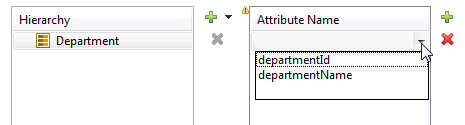
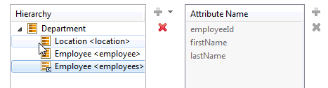
Tree bindings are used to display a collection of data in forms requiring a nested data structure. For example, if you are displaying an organization chart, for the organization entities such as Department, Location, and Employee, a tree binding is used to display the parent and each child node using a unique type. So, if Department is the root entity type, you can bind and show attributes of Department, such as Department Name and ID, as well as show attributes for child entity types Location and Employee.
The system adds the ADF Tree component for a tree or hierarchical format, or the ADF Table component for a tabular display. For display such as organization charts or for any nested structure, the Hierarchy Viewer component is used.
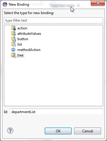
To add a new tree binding:
- In the Outline section of the Page Definition editor, click the New icon and then select Binding.
- In the New Binding dialog, select Tree and enter the ID. Click OK. The binding is added.
To add or change binding attributes for the new binding that you just created.
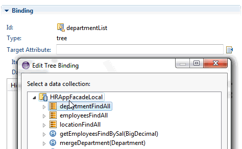
- Add and edit attributes for new bidings on the right side of the Page Definition editor. Click on the page icon for Target Attribute. In the Edit Tree Binding dialog, select the data collection to bind. Click OK.
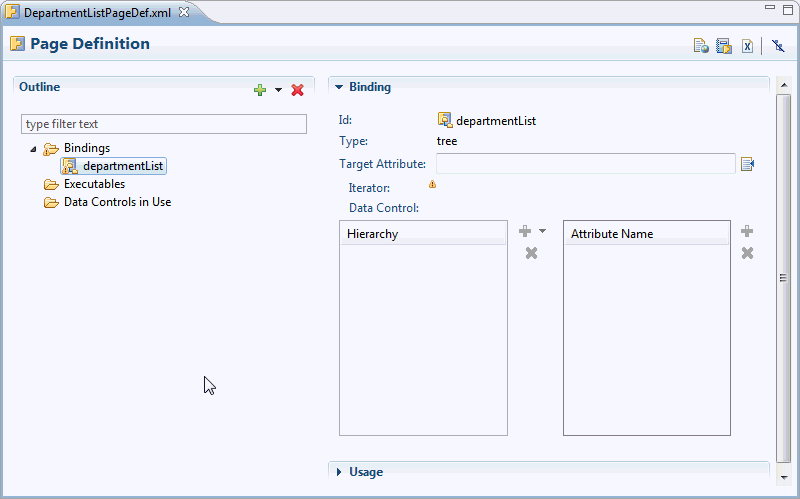
- The editor displays the entity type of the data collection in the Hierarchy section on the left.
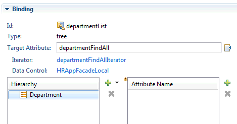
- Click Add (plus icon) in the Attribute Name section on the right to select the attributes of the entity data type you added to the Hierarchy section.
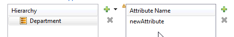
- Double-click on the newAttribute entry and click on the drop-down icon to select the attribute.
- To add a new entity type as a child of the selected node, Click Add in the Hierarchy section and select from the available type. Repeat steps 3-4 to select attributes of the type.
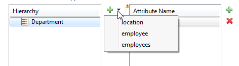
Note that there are two categories of nodes in the Hierarchy section. There are concrete categories which allow selection of attributes, and virtual categories which have been defined previously in the tree binding structure.
For more information about bindings and executables, see sections 12.6.2.1 ("Bindings Binding Objects") and 12.6.2.2 ("Executable Binding Objects") in the "Using ADF Model in a Fusion Web Application" chapter of the Oracle Fusion Middleware Fusion Developer's Guide for Oracle Application Development Framework.
2.4.6 Adding Data Binding to Existing UI Components
While the Data Palette enables you to design and create bound components in a single drag-and-drop action, in some cases, it may be preferable to create the basic UI components first and add the bindings later. For example, you can first create an ADF Faces component, and then bind it to the correct ADF control. Additionally, you can also rebind a UI component to a different data control.
When designing web pages, keep in mind that ADF bindings can be added only to certain ADF Faces tags. The following table lists the ADF Faces tags to which you can add ADF bindings.
| ADF Faces Tags Used in ADF Bindings |
| Text Fields |
af:inputText |
af:outputText |
af:outputLabel |
af:inputDate |
| Tables |
af:table |
| Actions |
af:commandButton |
af:commandLink |
af:commandMenuItem |
af:commandToolbarButton |
| Selection Lists |
af:inputListOfValues |
af:selectOneChoice |
af:selectOneListbox |
af:selecOneRadio |
af:selectBooleanCheckbox |
To apply ADF Model data binding to existing UI components:
- In source editor for your page, select the UI component to which you want to add ADF bindings. When you select a component in the editor, OEPE simultaneously selects that component tag in the Outline window.
- On the Properties pane, click the Bind to ADF Control toolbar button on the top right.
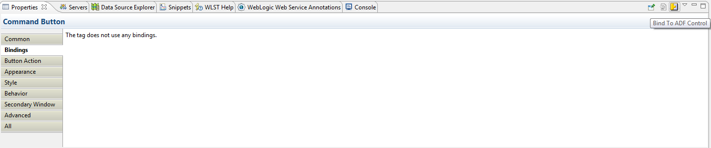
Note: Your project must already contain data controls for the Bind to ADF Control button to appear.
- On the Select Data Control dialog, select an ADF Data Control or one of its properties. You must select a compatible control or property to continue. Click OK.
To rebind an existing UI component:
- In source editor for your page, select the UI component you want to rebind to a different data control. When you select a component in the editor, OEPE simultaneously selects that component tag in the Outline window.
- On the Properties pane, click the Bind to ADF Control toolbar button on the top right.
- On the Select Data Control dialog, select the new data control or data control property you want to bind the UI component to. You must select a compatible control or property to continue. Click OK.
Depending on the UI component being rebound, OEPE displays a dialog where you can re-enter properties for the component. For example, if you are rebinding an ADF Table, the Edit Table dialog is displayed.
- Specify properties for your component and click Finish to complete rebinding.
2.4.7 Debugging ADF Bindings
You can debug ADF bindings by setting breakpoints in the page definition editor. For more information, see Setting and Using ADF Page Definition Breakpoints.
2.4.8 ADF Page Definition Artifact Validation
OEPE provides real-time and on-demand validation of your
page definition files even while the page definition editor is closed.
Page definition validation warnings and errors are reported in the Markers view
under the section ADF
Page Definition Problems.
You can set workspace preferences for ADF page definition validation from the Preferences
dialog.
To specify preferences for ADF page definition validation:
- From the main menu, select Window > Preferences to open the
Preferences dialog.
- In the Preferences dialog, select ADF > Artifact Validation to open the Artifact Validation page.
- Specify validation options as per your preference:
- Disable validation: Click to
stop ADF page definition validation.
- Reduce all validation errors to warnings: Selected by default.
Deselect if you want validation issues to be reported as errors, thereby preventing
deployment to WebLogic Server. This option is disabled if Disable
validation is
selected.
- Run Validation: Click to run a workspace-wide validation based
on current saved preferences. This option is disabled if Disable
validation is
selected.
- On clicking OK or Apply:
-
If Disable
validation is unselected
or the Reduce all validation errors to warnings option was changed,
a workspace-wide validation occurs.
- If Disable validation is selected, all ADF Validation Markers are deleted.
- Open page definition editors immediately reflect the changes.
2.4.9 Refactoring ADF Bindings
You can perform several refactoring options on ADF data binding artifacts using the AppXRay dependency engine. For more information, see Refactoring ADF Data Binding Artifacts.