| Skip Navigation Links | |
| Exit Print View | |

|
Netra Server X3-2 HTML Document Collection |
Front Panel Components (Installation)
Rear Panel Components (Installation)
Confirming Server and Site Specifications
Minimum Clearance for Service Access
AC and DC Power Supply Specifications
Overcurrent Protection Requirements
DC Power Source, Power Connection, and Grounding Requirements
Installing the Server in a 4-Post Rack
Installing the Standard 19-Inch Hardmount Kit (4-Post Rack)
Installing the 19-Inch Sliding-Rail Kit (4-Post Rack)
Installing the 600-mm Hardmount Kit (4-Post Rack)
Installing the Server in a 2-Post Rack
Installing the 19-Inch Hardmount Kit (2-Post Rack)
19‐Inch Hardmount Rack Kit (2-Post Rack)
Install the Server (2-Post, 19‐Inch Hardmount Rack Kit)
Installing the 19-Inch Sliding-Rail Kit (2-Post Rack)
19-Inch Sliding-Rail Kit (2-Post Rack)
Installing the 23-Inch Hardmount Kit (2-Post Rack)
23‐Inch Hardmount Kit (2-Post Rack)
Install the Server (23‐Inch Hardmount Kit)
Connecting Data and Management Cables
Powering On the Server the First Time
Assembling DC Power Cords and Applying DC Power
Power On the Host for the First Time
Choosing an OS Installation Method
OS Installation Task Map (Oracle Solaris)
OS Installation Task Map (Oracle VM)
OS Installation Task Map (Linux)
OS Installation Task Map (VMware ESXi)
OS Installation Task Map (Windows)
Supported OS Versions and Documentation
Understanding Installation Methods
Configuring the Preinstalled Oracle Solaris OS
Preinstalled OS RAID Limitations
Configuration Worksheet (Oracle Solaris)
Configure the Preinstalled Oracle Solaris OS
Configuring the Preinstalled Oracle VM 3. 0 Software
Configuration Worksheet (Oracle VM Server)
Configure the Preinstalled Oracle VM 3.0 OS
Preparing Your PXE Environment
Accessing Installation Utilities
RAID Configuration Requirements
Post-Installation RAID Volume Creation
Configuring RAID Volumes (LSI BIOS Utilities)
Performing Post-Installation Tasks
(Optional) Assign Boot Drive Priorities
Oracle VM Post-Installation Information
Performing Linux Post-Installation Tasks
Performing VMware ESXi Post-Installation Tasks
Performing Windows Post-Installation Tasks
Understanding Administration Resources
BIOS Overview (Administration)
Hardware RAID Administration Tools
Multiple Server Management Tools
Accessing Administration Tools
Access Add-On Card Configuration Utilities (BIOS)
Change Telco Alarm States Manually
Configuring Power-On and Boot Options
Change the Oracle ILOM Root Password (Oracle ILOM CLI)
Recover the Oracle ILOM Root Password
Configuring Oracle ILOM (Oracle ILOM Web Interface)
Configuring the SP and Oracle ILOM (BIOS)
Configure the SP and Oracle ILOM (OSA)
Configure the Enhanced PCIe Cooling Mode Policy (Oracle ILOM CLI)
Resetting the BIOS to Default Settings
Configuring Legacy Option ROM Allocation
Configuring I/O Resource Allocation
Obtain the Server Serial Number
Locate the Server (Oracle ILOM Web Interface)
Monitoring the Server Health (Oracle ILOM Web Interface)
Updating the Firmware and Software
Obtain and Update Firmware (OSA)
Mounting the Oracle System Assistant USB Flash Drive
Requesting Updates on Physical Media
Component Locations (Storage, Power, and Fans)
Component Locations (Motherboard, Memory, and PCIe3 Cards)
Front Panel Components (Service)
Rear Panel Components (Service)
Troubleshooting (Oracle ILOM /SP Targets)
Troubleshooting (Oracle ILOM /System Targets)
Troubleshooting (Oracle ILOM Legacy Targets)
Component Service Task Reference
Removing Power From the Server
Raise the Drive Cage to the Service Position
Remove a PCIe3 Card (Risers 1 and 2)
Install a PCIe3 Card (Risers 1 and 2)
Install a PCIe3 Card (Riser 3)
Install the Drive Signal Cable
Determine if the Drive Backplane Is Faulty
Determine if the LED Board Is Faulty
Determine if the Motherboard Is Faulty
Determine if the PDB Is Faulty
Returning the Server to Operation
Power On the Server (Oracle ILOM)
Note - The 19-inch, 2-post sliding rail mount kit supports rack web thicknesses (the width of the rack post) of 3 in. (76.20 mm), 4 in. (101.6 mm), and 5 in. (127 mm).
Note - The front-to-back rail spacing must be at least 15.43 in. (392 mm) and not more than 34 in. (863.6 mm) from the outside face of the front rail to the outside face of the back rail.
See Handling Precautions and ESD Precautions.
See Rack Cautions and Stabilize the Rack.
|
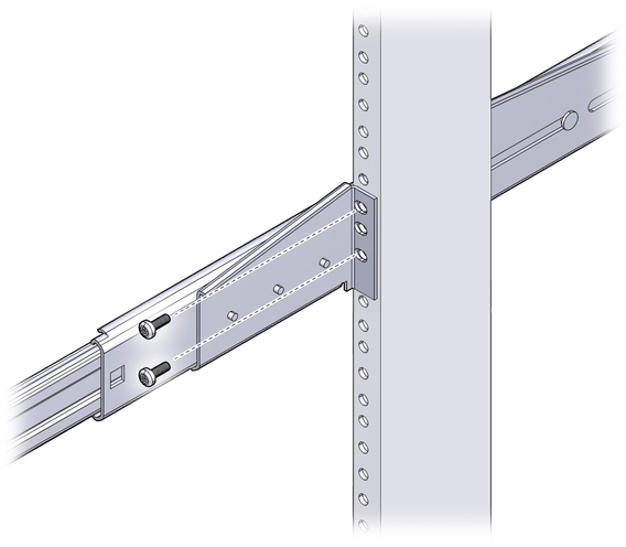
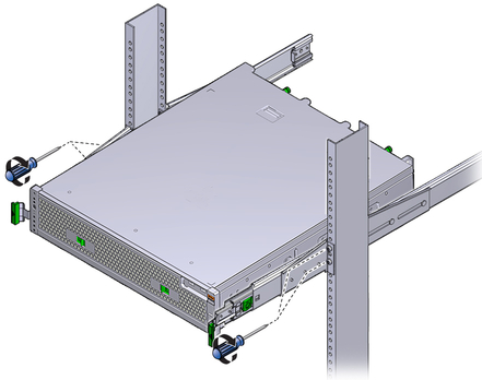
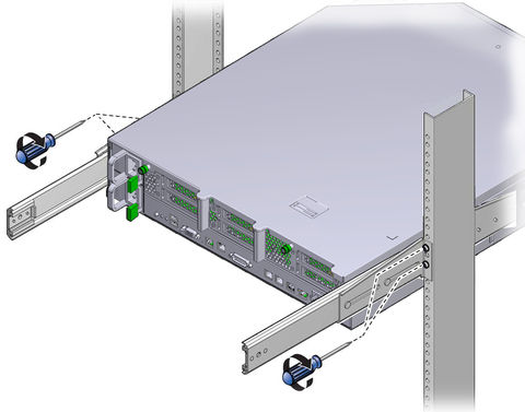
To secure each bracket, use two of the M5 x 12.7 mm screws or two of the M6 x 13 mm screws. Tighten the screws enough to secure the brackets, but leave the brackets loose enough for adjustment later.
To secure each bracket, use two of the M5 x 12.7 mm screws or two of the M6 x 13 mm screws, as you did in Step 8. Tighten the screws enough to secure the brackets, but leave the brackets loose enough for adjustment later.
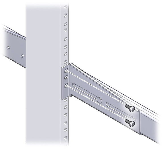
Note - If your rack has 10–32 holes, use the 10–32 collar screws and 10–32 threaded strips.
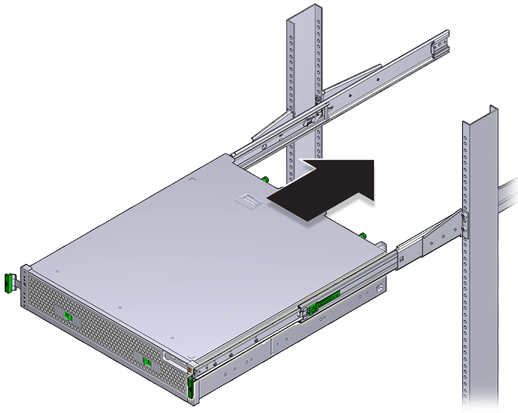
You might find that there is too much or too little room between the two slides mounted in the rack, consequently the glides attached to the server might not align correctly with the slides in the rack. If either situation occurs, loosen the screws on the front and back brackets (Step 8 and Step 9), move the brackets inward or outward to the appropriate points, then tighten the brackets again.
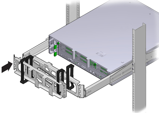
There are labels on both the rails and the CMA. The CMA side that has an arrow attaches to the right inner glide. The other side of the CMA attaches to the outer member.
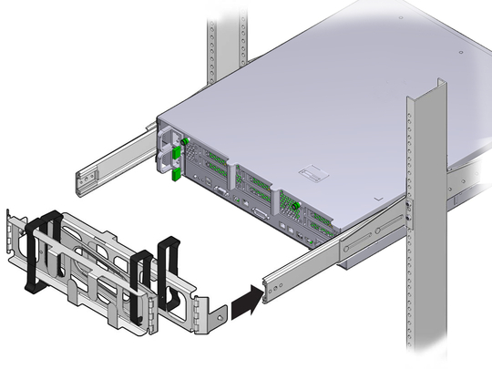
There are labels on both the rails and the CMA. The CMA side that has an arrow attaches to the left inner glide. The other side of the CMA attaches to the outer member.
See Connecting Cables.