JavaScript is required to for searching.
Skip Navigation Links
Exit Print View
Netra Server X3-2 HTML Document Collection
search filter icon
search icon

Document Information

Using This Documentation

Product Notes

Related Documentation

Feedback

Access to Oracle Support

Installation

Understanding the Server

Installation Task Overview

Server Overview

Front Panel Components (Installation)

Rear Panel Components (Installation)

Confirming Server and Site Specifications

Physical Specifications

Minimum Clearance for Service Access

AC and DC Power Supply Specifications

Input Power Information

Overcurrent Protection Requirements

DC Power Source, Power Connection, and Grounding Requirements

Environmental Requirements

Acoustic Noise Emissions

Airflow Clearance

Preparing for Installation

Shipping Kit Inventory

Handling Precautions

ESD Precautions

Tools Needed for Installation

Optional Components

Rack Cautions

Stabilize the Rack

Installing the Server in a 4-Post Rack

Installing the Standard 19-Inch Hardmount Kit (4-Post Rack)

19‐Inch Hardmount Kit (4-Post Rack)

Install the Server (4-Post, 19‐Inch Hardmount Kit)

Installing the 19-Inch Sliding-Rail Kit (4-Post Rack)

19-Inch Sliding Rail Kit (4-Post Rack)

Install the Server (4-Post, 19-Inch Sliding Rail Kit)

Installing the 600-mm Hardmount Kit (4-Post Rack)

600‐mm Hardmount Kit (4-Post Rack)

Install the Server (4-Post, 600‐mm Hardmount Kit)

Installing the Server in a 2-Post Rack

Installing the 19-Inch Hardmount Kit (2-Post Rack)

Installing the 19-Inch Sliding-Rail Kit (2-Post Rack)

Installing the 23-Inch Hardmount Kit (2-Post Rack)

Connecting Cables

Connecting Data and Management Cables

Identifying Ports

Powering On the Server the First Time

Connect AC Power Cords

Assembling DC Power Cords and Applying DC Power

Power On the Host for the First Time

OS Installation

Choosing an OS Installation Method

OS Installation Task Map (Oracle Solaris)

OS Installation Task Map (Oracle VM)

OS Installation Task Map (Linux)

OS Installation Task Map (VMware ESXi)

OS Installation Task Map (Windows)

Supported OS Versions and Documentation

Oracle Linux Support Kernel

Understanding Installation Methods

Configuring the Preinstalled Oracle Solaris OS

Preinstalled OS RAID Limitations

Configuration Worksheet (Oracle Solaris)

Configure the Preinstalled Oracle Solaris OS

Configuring the Preinstalled Oracle VM 3. 0 Software

Configuration Worksheet (Oracle VM Server)

Configure the Preinstalled Oracle VM 3.0 OS

Oracle VM 3.0 Overview

Preparing to Install an OS

Selecting the Console Display

Selecting the Boot Media

Preparing Your PXE Environment

Accessing Installation Utilities

Setting Up BIOS

Configuring RAID

HBA and RAID Support

RAID Configuration Requirements

Post-Installation RAID Volume Creation

Configure RAID (OSA)

Configuring RAID Volumes (LSI BIOS Utilities)

Installing a Supported OS

Install an OS (OSA)

Installing an OS (Media)

Install an OS (PXE)

Performing Post-Installation Tasks

(Optional) Assign Boot Drive Priorities

Oracle VM Post-Installation Information

Performing Linux Post-Installation Tasks

Performing VMware ESXi Post-Installation Tasks

Performing Windows Post-Installation Tasks

Administration

Understanding Administration Resources

Common Administration Tools

Oracle ILOM Overview

BIOS Overview (Administration)

OSA Overview

HMP

Hardware RAID Administration Tools

Multiple Server Management Tools

Accessing Administration Tools

Accessing Oracle ILOM

Accessing BIOS

Accessing OSA

Access Add-On Card Configuration Utilities (BIOS)

Controlling the Server

Controlling the Power State

Change Telco Alarm States Manually

Configuring Power-On and Boot Options

Configuring Power-On Policies

Selecting a Boot Device

Configuring Oracle ILOM

Change the Oracle ILOM Root Password (Oracle ILOM CLI)

Recover the Oracle ILOM Root Password

Configuring Oracle ILOM (Oracle ILOM Web Interface)

Configuring the SP and Oracle ILOM (BIOS)

Configure the SP and Oracle ILOM (OSA)

Configure the Enhanced PCIe Cooling Mode Policy (Oracle ILOM CLI)

Configuring BIOS

Resetting the BIOS to Default Settings

Configuring Legacy Option ROM Allocation

Configuring I/O Resource Allocation

Configuring Devices in BIOS

Enabling or Disabling OSA

Disable OSA

Enable OSA

Monitoring the Server

Obtain the Server Serial Number

Locate the Server (Oracle ILOM Web Interface)

Obtaining Server Information

Monitoring the Server Health (Oracle ILOM Web Interface)

Understanding SNMP Traps

Updating the Firmware and Software

Update to a New OSA Release

Obtain and Update Firmware (OSA)

Restore OSA

Mounting the Oracle System Assistant USB Flash Drive

Obtaining Updated Software

Requesting Updates on Physical Media

Service

Identifying Components

Component Locations (Storage, Power, and Fans)

Component Locations (Motherboard, Memory, and PCIe3 Cards)

Front Panel Components (Service)

Rear Panel Components (Service)

Detecting and Managing Faults

Understanding Diagnostics

Interpreting Diagnostic LEDs

Troubleshooting (Oracle ILOM /SP Targets)

BIOS POST Event Messages

Troubleshooting (Oracle ILOM /System Targets)

Displaying Faulty Components

Troubleshooting (Oracle ILOM Legacy Targets)

Troubleshooting (Pc-Check)

Preparing for Service

Safety Information

Tools Needed for Service

Filler Panels

Find the Server Serial Number

Component Service Task Reference

Locate the Server

Removing Power From the Server

Accessing Internal Components

Remove the Fan Tray

Raise the Drive Cage to the Service Position

Remove the Air Duct

Remove the PDB Duct

Servicing the Filter

Remove the Filter

Install the Filter

Servicing Drives

Drive Configuration

Drive LEDs

Locate a Faulty Drive

Remove a Drive

Install a Drive

Verify a Drive

Servicing the DVD Drive

Remove the DVD Drive

Install the DVD Drive

Servicing Power Supplies

Power Supply LEDs

Locate a Faulty Power Supply

Remove a Power Supply

Install a Power Supply

Verify a Power Supply

Servicing Fan Modules

Fan Module LEDs

Locate a Faulty Fan Module

Remove a Fan Module

Install a Fan Module

Verify a Fan Module

Servicing Risers

Riser Configuration

Locate a Faulty Riser

Remove a Riser

Install a Riser

Verify a Riser

Servicing PCIe3 Cards

PCIe3 Card Configuration

Locate a Faulty PCIe3 Card

Remove a PCIe3 Card (Risers 1 and 2)

Remove a PCIe3 Card (Riser 3)

Install a PCIe3 Card (Risers 1 and 2)

Install a PCIe3 Card (Riser 3)

Verify a PCIe3 Card

Servicing the Battery

Remove the Battery

Install the Battery

Servicing the USB Drive

USB Drive LED

Remove the USB Drive

Install the USB Drive

Servicing Cables

Cable Configuration

Remove the Drive Signal Cable

Install the Drive Signal Cable

Remove the Drive Power Cable

Install the Drive Power Cable

Remove the DVD SATA Cable

Install the DVD SATA Cable

Remove the PDB Signal Cable

Install the PDB Signal Cable

Servicing the Drive Backplane

Drive Backplane Configuration

Determine if the Drive Backplane Is Faulty

Remove the Drive Backplane

Install the Drive Backplane

Verify the Drive Backplane

Servicing DIMMs

DIMM Configuration

Locate a Faulty DIMM

Remove a DIMM

Install a DIMM

Verify a DIMM

Servicing CPUs

CPU Configuration

Locate a Faulty CPU

CPU Tool

Remove a CPU

Install a CPU

Servicing the LED Board

Determine if the LED Board Is Faulty

Remove the LED Board

Install the LED Board

Verify the LED Board

Servicing the USB Board

Remove the USB Board

Install the USB Board

Servicing the Motherboard

Determine if the Motherboard Is Faulty

Remove the Motherboard

Install the Motherboard

Verify the Motherboard

Servicing the PDB

Determine if the PDB Is Faulty

Remove the PDB

Install the PDB

Verify the PDB

Returning the Server to Operation

Install the PDB Duct

Install the Air Duct

Secure the Drive Cage

Install the Fan Tray

Install the Top Cover

Connect Power Cords

Power On the Server (Oracle ILOM)

Power On the Server (Power Button)

Glossary

Index

Install the Server (4-Post, 19-Inch Sliding Rail Kit)


Note - The front-to-back rail spacing must be at least 15.43 in.(392 mm) and not more than 34 in. (863.6 mm) from the outside face of the front rail to the outside face of the back rail.


  1. Gather the required tools.

    See Tools Needed for Installation.

  2. Read the server cautions.

    See Handling Precautions and ESD Precautions.

  3. Read the rack cautions and stabilize the rack.

    See Rack Cautions and Stabilize the Rack.

  4. Get the hardmount brackets and M5 x 4.5 mm flathead Phillips screws from the standard rack kit.

    These hardmount brackets and screws are shipped with the standard server shipping kit, not as part of the 4-post, 19-inch sliding rail kit. See 19‐Inch Hardmount Kit (4-Post Rack).
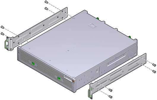
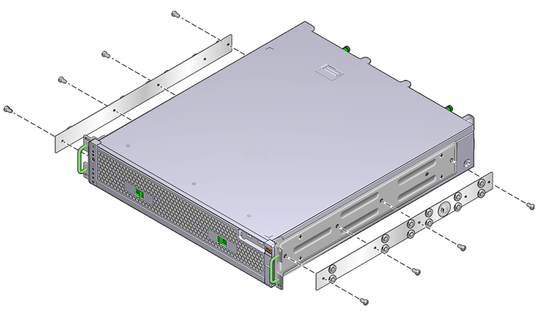
  5. Use four of the supplied M5 x 4.5 mm flathead Phillips screws to secure each of the hardmount brackets to the sides of the server.
    image:Figure showing how to install the two hardmount brackets to the server.
  6. Get the telco slide assemblies from the rack kit.
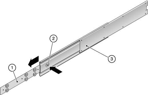
  7. Press in the button on each slide and pull the glide completely out of the slide.
    image:Figure showing how to dismantle the slide.
    No.
    Description
    1
    Glide
    2
    Button
    3
    Slide
  8. Using eight of the M4 x 0.5 x 5 mm panhead Phillips screws from the rackmount kit (four for each side), screw each glide to the side of the server chassis.
    image:Figure showing where to install glides to the server chassis.
  9. Get the short brackets and long brackets from the rackmount kit.
  10. Lift each short bracket to the desired position at the front of the rack and attach a short bracket to each of the front rack uprights.

    Use two of the brass M6 collar screws and M6 cage nuts (if required), and one threaded strip, to secure each bracket.

  11. Lift each long bracket to the desired position at the rear of the rack and attach a long bracket to each of the rear rack uprights.

    To secure each bracket, use two of the brass M6 collar screws and M6 cage nuts (if required) and one threaded strip, exactly as you did for the front rack uprights in the previous step.
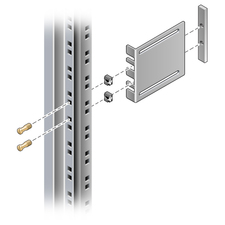

    image:Figure showing how to secure the brackets to the rack.

    Note - If your rack has 10–32 holes, use the 10–32 collar screws and 10–32 threaded strips.


  12. Extend a slide to line up the access holes with the front screw holes.
  13. Secure the slide onto the short and long brackets at the front and rear of the rack.

    Use the M5 panhead screws from the inside. Use the M5 nuts, plain washers, and star washers from the outside. Use extension brackets instead of the long brackets if the dimension is greater than 665 mm.
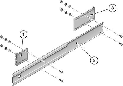

    image:Figure showing how to secure the slide to the brackets.
    No.
    Description
    1
    Short bracket
    2
    Slide
    3
    Long bracket
  14. Repeat Step 12 and Step 13 for the slide on the other side of the rack.
  15. Push the slides completely into the assembly on each side of the rack and release the stop catches.
  16. Align the glides attached to the server with the slide assemblies in the rack.

    You might find that there is too much or too little room between the two slides mounted in the rack. Consequently, the glides attached to the server might not align correctly with the slides in the rack. If either situation occurs, loosen the M6 collar screws and cage nuts on the long and short brackets (Step 10 and Step 11), move the brackets inward or outward to the appropriate points, then tighten them again.
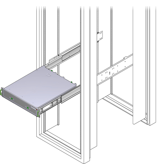
  17. Push in the slide buttons and slide the server all the way into the rack enclosure.
    image:Figure showing how to slide the server into a rack.
  18. Using two screws per side, secure the front of the hardmount brackets that are attached to the sides of the server to the front of the rack.

    The size of the screws varies, depending on your particular rack.
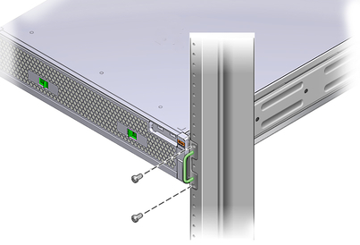

    image:Figure showing where to secure the front of the server to the rack.
  19. Connect required and optional cables.

    See Connecting Cables.

Related Information