3 SL3000 SCSI Commands
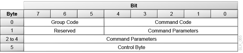
Command Descriptor Block (CDB) Structure
-
The first byte contains the operation code — a Group Code that provides eight groups of commands and a Command Code that provides 32 command codes for each group.
-
The second byte starts the command parameters.
-
The last byte is the control byte (see "Control Byte Structure").
For some commands, a list of parameters accompanies the request during data out. For all commands, if there is an invalid parameter in the CDB, then the library terminates the command without altering the medium.
Description of the illustration ''slk_065.png''
Description of the illustration ''slk_066.png''
Description of the illustration ''slk_067.png''
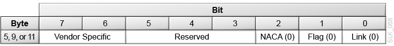
Control Byte Structure
The control byte is the last byte of every CDB.
Description of the illustration ''slk_068.png''
- Vendor Specific
-
Provides information about the device.
- NACA (Normal auto contingent allegiance)
-
Controls the rules for handling an auto contingent condition caused by a command. When NACA is 0, the command will return a check condition if a contingent allegiance condition occurs.
- Flag (not supported)
-
Causes an interrupt in the initiator allowing a device to respond with intermediate status. This bit is should be 0.
- Link (not supported)
-
Allows devices that support command linking to continue the I/O process. This bit should be 0.
Supported SCSI Command Status Byte Codes
- Good (00h)
-
Indicates the device successfully completed the command.
- Check Condition (02h)
-
Occurs when an error, unit exception, or abnormal condition generates sense data caused by one of the following conditions:
-
Issuing an invalid command or parameter
-
Issuing a command to a device that is not ready
-
Detecting a hardware error
-
Sensing an illegal request
-
- Busy (08h)
-
Occurs when the target cannot accept a command from an otherwise acceptable initiator. Normally, to recover from a Busy status, the initiator reissues the command.
- Reservation Conflict (18h)
-
Occurs whenever a SCSI initiator attempts to access a logical unit that is reserved by another initiator.
Initialize Element Status (07h)
Initialize Element Status (07h) requests an audit of the library. The library accepts this command for compatibility, but it does not perform any action.
At power-on or after the front door opens/closes, the library performs a full audit and then maintains a cartridge inventory during operation. Use Read Element Status (B8h) to obtain the cartridge inventory.
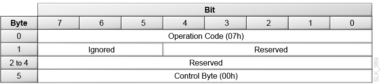
Description of the illustration ''slk_069.png''
Initialize Element Status with Range (37h)
Initialize Element Status with Range (37h) requests an audit for a range of cells in the library. The library accepts this command for compatibility, but it does not perform any action.
At power-on or after the front door opens/closes, the library performs a full audit and then maintains a cartridge inventory while operating. Use Read Element Status (B8h) to obtain the cartridge inventory.
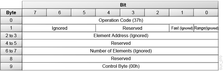
Description of the illustration ''slk_070.png''
Inquiry (12h)
Inquiry (12h) requests information about library parameters.
Note:
The Inquiry command returns Check Condition (02h) status only when it cannot return the requested data. This command will not clear any pending unit attention conditions.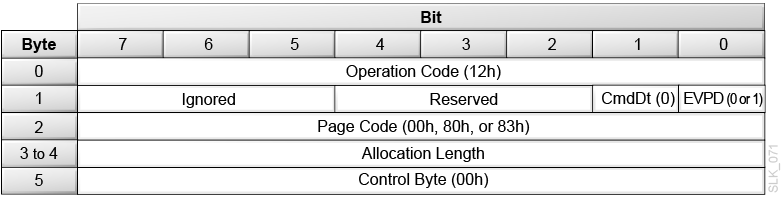
Description of the illustration ''slk_071.png''
- CmdDt (Command Support Data - not supported)
-
Set to 0.
- EVPD (Enable vital product data)
-
0 = Requests standard inquiry data
1 = Requests vital support product data
- Page Code
-
If EVPD is 0, set the page code to 00h.
If EVPD is 1, set the page code to:
-
00h = Supported vital product page
-
80h = Unit serial number page
-
83h = Device identification page
-
- Allocation Length
-
The library transfers either the number of bytes specified by the Allocation Length field or all of the available inquiry data, whichever is less. The page lengths are:
-
38h (56d) bytes for standard inquiry data
-
07h (7d) bytes for the supported vital product page
-
10h (16d) bytes or 16h (22d) bytes for the unit serial number page
-
2Ch (44d) bytes for the device identification page
-
Standard Inquiry Data Definition
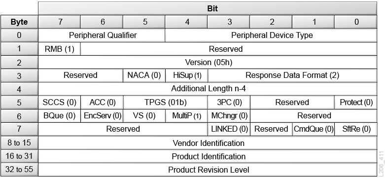
Description of the illustration ''l206_411.png''
- Peripheral Qualifier
-
000b = The specified peripheral device type is currently connected to this logical unit.
001b = The device server can support the specified peripheral device type on this logical unit. However, the physical device is not currently connected to this logical unit. The library returns this value when either:
-
The command was sent to an HLI library.
-
The command was sent to a partitioned library with at least one SCSI partition and the SCSI host issuing the command does not have a registered World Wide name within any current partition configuration. For more information, see "Configuring SCSI Access in a Partitioned Library".
011b = The command was sent to an unsupported logical unit.
-
- Peripheral Device Type
-
08h = The library is a medium changer device.
1Fh = The command was sent to an unsupported logical unit.
- RMB (Removable Medium)
-
1 = The medium is removable.
- Version
-
05h = The library complies with SCSI-3.
- NACA (Normal Auto Contingent Allegiance - not supported)
-
0 = The library does not support setting NACA to one in the control byte of a CDB.
- HiSup (Hierarchical Addressing Support)
-
1 = The library uses the hierarchical addressing module to identify logical units.
- Response Data Format
-
2 = The data complies with the SCSI-3 specification.
- Additional Length
-
1Fh = 31d bytes of remaining Standard Inquiry Data.
- SCCS
-
0 = The library does not contain an embedded storage array controller component.
- ACC (Access Control Coordinator)
-
0 = The library does not contain an ACC that may be addressed through this logical unit.
- TPGS (Target Port Group Support)
-
1 = The library supports implicit asymmetric logical unit access. The library can change target port asymmetric access states without a Set Target Port Groups (which is an unsupported command). The library supports Report Target Port Groups (A3h).
- 3PC (Third-Party Commands - not supported)
-
The library returns 0.
- Protect (Information Protection - not supported)
-
The library returns 0.
- BQue (Basic Queuing - not supported)
-
The library returns 0.
- VS (Vendor Specific)
-
0 = There is no vendor specific information with this command.
- MultiP
-
0 = The library has a single target port.
1 = The library has multiple target ports. There is a multi-port fibre channel card installed in the library
- MChngr
-
0 = The library is not embedded in or attached to a medium transport element.
- LINKED (Linked commands - not supported)
-
The library returns 0.
- CmdQue (Command Queuing - not supported)
-
The library returns 0.
- SftRe (Soft Reset - not supported)
-
The library returns 0.
- Vendor Identification
-
Contains the ASCII character sequence ”STK” followed by blanks. If the specified logical unit is not supported, this field contains all blanks.
- Product Identification
-
Contains the ASCII character sequence ”SL3000” followed by blanks.
- Product Revision Level
-
Contains an ASCII character sequence that represents the product revision level.
- Error Conditions
-
The library returns Check Condition status for the Inquiry command only when a severe error occurs. To recover from a Check Condition status report on the Inquiry command, verify that the Inquiry CDB is correct and then retry the Inquiry command.
Supported Pages
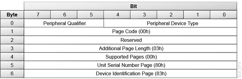
Description of the illustration ''slk_073.png''
- Peripheral Qualifier
-
See Peripheral Qualifier.
- Peripheral Device Type
- Page Code
-
00h = The vital page
- Additional Page Length
-
03h (3d) bytes
- Supported pages
-
00h = The first vital page is page 0 (current page)
80h = Unit Serial Number Page
Unit Serial Number Page
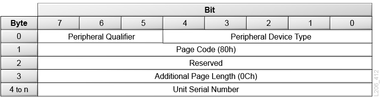
Description of the illustration ''l206_412.png''
- Peripheral Qualifier
-
See Peripheral Qualifier.
- Peripheral Device Type
- Page Code
-
80h = The unit serial number page.
- Additional Page Length
-
0Ch = 12 bytes of unit serial number data.
- Unit Serial Number
-
Contains a unique ASCII Serial Number for the library. For example:
-
571XX0000121 = 12 byte unit serial number
Where XX indicates the library partition identifier. For nonpartitioned libraries, XX is 00.
-
Device Identification Page
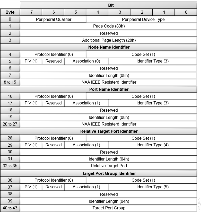
Description of the illustration ''slk_075.png''
- Peripheral Qualifier
-
See Peripheral Qualifier.
- Peripheral Device Type
- Protocol Identifier
-
0h = Fibre Channel protocol.
- Code Set
-
1 = Binary values
- PIV (Protocol Identifier Valid)
-
1 = The protocol identifier is valid
- Association
-
0 = The identifier field is associated with the addressed logical unit
1 = The identifier field is associated with the port that received the request
- Identifier Type
-
3 = Contains a 64-bit IEEE formatted address
4 = Contains the Relative Target Port Identifier
5 = Contains the Target Port Group Identifier
- Identifier Length
-
04h = 4-bytes long
08h = 8-bytes long
- NAA IEEE Registered Identifier
-
An 8-byte identifier. The first 4 bits are the Name Address Authority — NAA (5h). The next 24 bits are the Oracle company ID (00 10 4Fh). The remaining bits are the vendor-specific identifier. The NAA IEEE Registered Identifier is unique for each library and Fibre Channel port.
- Relative Target Port
-
01h = Port 1
02h = Port 2
03h = Port 3
04h = Port 4
- Target Port Group
-
01h = Target Port Group 1
02h = Target Port Group 2
Log Sense (4Dh)
Log Sense (4Dh) returns library error logs and statistics.
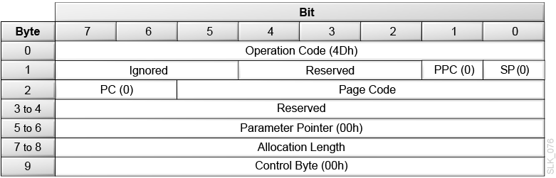
Description of the illustration ''slk_076.png''
- PPC (Parameter Pointer Control - not supported)
-
Set this to 0.
- SP (Save Parameters - not supported)
-
Set this to 0.
- PC (Page Control)
-
Set this to 0. The library only supports a PC value of 0 (threshold values).
- Page Code
-
00h = List supported pages
07h = List last n error events page
- Parameter Pointer
-
Set this to 0.
- Allocation Length
-
The library transfers either the number of bytes specified by the Allocation Length field or all of the available log sense data, whichever is less. The page lengths are:
-
06h (6d) bytes for supported pages data
-
28h (40d) bytes for the last n errors events page
-
Supported Pages Page
The Supported Pages Page lists all the Log Sense page codes supported by the library.
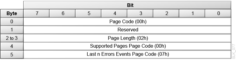
Description of the illustration ''slk_077.png''
Last n Errors Events Page
The Last n Errors Event Page does not return specific error information. Instead, the operator should gather the log/error information from SLC.
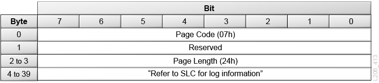
Description of the illustration ''l206_413.png''
Mode Select 6-byte (15h) and Mode Select 10-byte (55h)
The Mode Select commands specify operating parameters for the library. The library uses the configuration parameters during power-on or after a logical unit reset. If you set the parameter list length field to 0, then no Mode Select data is required. Otherwise, you must provide the following mode parameter data in a parameter list:
-
A 4-byte or 8-byte Mode Select Parameter Header
-
An 8-byte Fibre Channel Logical Unit Page
-
An 8-byte Fibre Channel Port Control Page
-
A 20-byte Element Address Assignment Mode Page
The library accepts the Mode Select command for compatibility, but the library does not support changing Mode parameters. The library returns a check condition if a SCSI host issues a Mode Select command and attempts to change a mode page. When the library receives a Mode Select command, the library validates all parameters. If a value is invalid, the library returns an error.
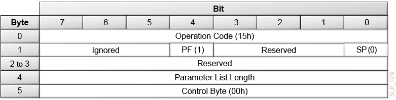
Description of the illustration ''slk_079.png''
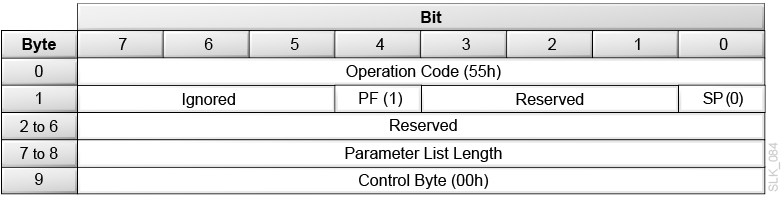
Description of the illustration ''slk_084.png''
- PF (Page Format)
-
Set this to 1 to indicate the page format supports the SCSI-3 specification
- SP (not supported)
-
Set this to 0.
- Parameter List Length
-
00h = Transfers no data. This is not an error.
18h (for 6-byte) or 1Ch (for 10-byte) = Transfers Mode Parameter Header and Element Address Assignment Page
0Ch (for 6-byte) or 10h (for 10-byte) = Transfers the Mode Parameter Header and Fibre Channel Logical Unit Page
0Ch (for 6-byte) or 10h (for 10-byte) = Transfers the Mode Parameter Header and Fibre Channel Port Control Page
Any other value is an error and is not supported.
Mode Select Parameter Header
The header definitions for the library must all be 00h.
Mode Select 6-byte Parameter Header
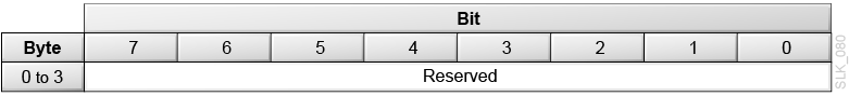
Description of the illustration ''slk_080.png''
Mode Select 10-byte Parameter Header
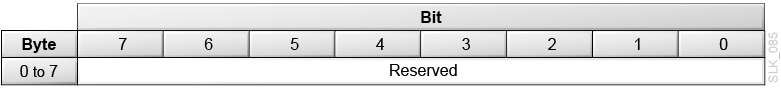
Description of the illustration ''slk_085.png''
Fibre Channel Logical Unit Page
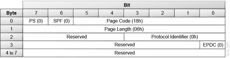
Description of the illustration ''slk_081.png''
- PS (Parameters Savable)
-
Set this to 0.
- SPF (SubPage Format)
-
Set this to 0 to indicate page_0 format.
- Protocol Identifier
-
0h = Fibre Channel protocol.
- EPDC (Enable Precise Delivery Checking - not supported)
-
Set this to 0.
Fibre Channel Port Control Page
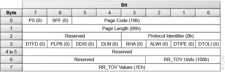
Description of the illustration ''slk_082.png''
- PS (Parameters Savable)
-
Set this to 0.
- SPF (SubPage Format)
-
SubPage Format. Set this to 0 to indicate page_0 format.
- Protocol Identifier
-
0h = FC protocol.
- DTFD (Disable Target Fabric Discovery)
-
Set this to 0.
- PLPB (Prevent Loop Port Bypass)
-
Set this to 0.
- DDIS (Disable Discovery)
-
Set this to 0.
- DLM (Disable Loop Master)
-
Set this to 0.
- RHA (Require Hard Address)
-
Set this to 0.
- ALWI (Allow Login without Loop Initialization)
-
Set this to 0.
- DTIPE (Disable Target Initiated Port Enable)
-
Set this to 0.
- DTOLI (Disable Target Originated Loop Initialization)
-
Set this to 0.
- RR_TOV Units (Resource Recovery Timeout Units)
-
Set this to 100b = 10 second units.
- RR_TOV Values (Resource Recovery Timeout Value)
-
Set this to 1Eh = 300 seconds.
Element Address Assignment Mode Page
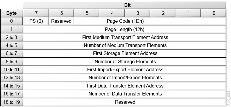
Description of the illustration ''slk_083.png''
- PS (Parameters Savable)
-
Set this to 0.
- Page Code
-
1Dh = Element Address Assignment mode page.
- Parameter Length
-
12h = 18d bytes of parameter data following this byte
- First Medium Transport Element Address
-
0000h = The address of the robot in the library.
- Number of Medium Transport Elements
-
The number of the robots in the library. The number must be the same number returned by Mode Sense.
- First Storage Element Address
-
7D0h (2000d) = The address of the first data cartridge cell in the library or partition.
- Number of Storage Elements
-
The number of data cartridge cells in the library or partition. This number depends on the configuration of the library or partition. The number must be the same number returned by Mode Sense. To obtain this value, use Mode Sense of mode page 1Dh.
- First Import/Export Element Address
-
000Ah (10d) = The address of the first CAP in the library or partition.
- Number of Import/Export Elements
-
The number of CAPs in the library or partition. This number depends on the configuration of the library or partition. The number must be the same number returned by Mode Sense. To obtain this value, use Mode Sense of mode page 1Dh.
- First Data Transfer Element Address
-
3E8h (1000d) = The address of the first drive in the library or partition.
- Number of Data Transfer Elements
-
The number of drives in the library. This number depends on the configuration of the library. The number must be the same number returned by Mode Sense. To obtain this value, use Mode Sense of mode page 1Dh.
Mode Sense 6-byte (1Ah) and Mode Sense 10-byte (5Ah)
The Mode Sense commands return information about the library's operating mode parameters. The data can be truncated to the length specified in the allocation length field. The library returns a Mode Sense Parameter Header followed by one or more of the following mode pages:
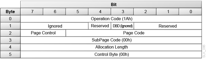
Description of the illustration ''slk_086.png''
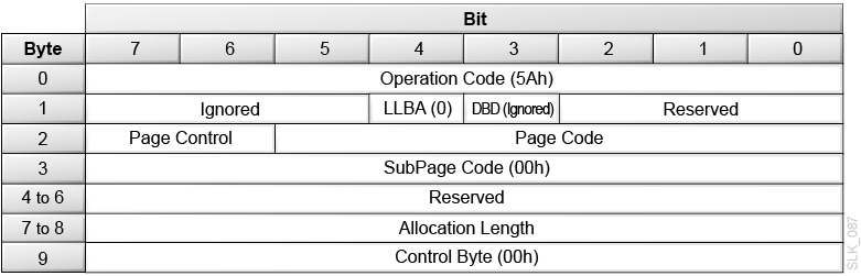
Description of the illustration ''slk_087.png''
- LLBA (10-byte only)
-
Set this to 0. The library will return 0 for LONGBLA in the parameter data.
- DBD (Disable Block Descriptor)
-
The library ignores this field.
- Page Control
-
0h (00b) = Current Values. The library returns the requested pages with each supported parameter set to its current value.
1h (01b) = Changeable Parameter Values. The library returns the requested pages indicating which parameters the initiator can change (1 indicates a changeable parameters and 0 indicates an unchangeable parameter).
Note:
The library does not support any changeable mode values.2h (10b) = Default Values. The library returns the requested pages with each supported parameter set to its default. The default values are the same as the current values.
3h (11b) = Saved Values. The library does not support any savable pages. If you request Saved Values, the library returns a check condition.
- Page Code
-
18h = Fibre Channel Logical Unit page
19h = Fibre Channel Port Control page
1Dh = Element Address Assignment page
1Eh = Transport Geometry page
1Fh = Device Capabilities page
3Fh = All pages (in the above order)
- SubPage Code (not supported)
-
Set this to 0.
- Allocation Length
-
The length of the parameter list returned by the library. The maximum length for Mode Sense 6-byte is 40h (64d) bytes. The maximum length for Mode Sense 10-byte is 44h (68d) bytes.
The library transfers the number of bytes specified by the Allocation Length or the available Mode Sense data, whichever is less. The length varies based on the Page Code selected:
-
4 bytes (for Mode Sense 6-byte) or 8 bytes (for Mode Sense 10-byte) for the parameter list header which is always present.
-
8 additional bytes for the Fibre Channel Logical Unit Control page
-
8 additional bytes for the Fibre Channel Port Control page
-
20 additional bytes for the Element Address Assignment page
-
4 additional bytes for the Transport Geometry page
-
20 additional bytes for the Device Capabilities page
-
Mode Sense Parameter Header
Mode Sense 6-byte Parameter Header
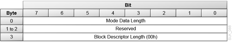
Description of the illustration ''slk_088.png''
Mode Sense 10-byte Parameter Header
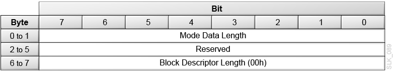
Description of the illustration ''slk_089.png''
- Mode Data Length
-
The bytes of parameter information available regardless of the allocation length. This value excludes the Mode Data Length byte, but includes three additional bytes (for Mode Sense 6-byte) or six additional bytes (for Mode Sense 10-byte) and the length of any mode pages that follow.
- Block Descriptor Length (not supported)
-
The library returns 0.
FC Logical Unit Control Page
Description of the illustration ''slk_081.png''
- PS (Parameters Saveable)
-
The library returns 0.
- SPF (SubPage Format)
-
The library returns 0 to indicate page_0 format.
- Protocol Identifier
-
0h = Fibre Channel protocol.
- EPDC (Enable Precise Delivery Checking)
-
The library returns 0.
FC Port Control Page
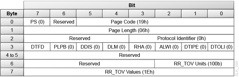
Description of the illustration ''slk_090.png''
- PS (Parameters Savable)
-
The library returns 0.
- Protocol Identifier
-
0h = FC protocol.
- DTFD (Disable Target Fabric Discovery)
-
0 = Public Loop supported
1 = Private Loop only supported
- PLPB (Prevent Loop Port Bypass)
-
The library returns 0.
- DDIS (Disable Discovery)
-
The library returns 0.
- DLM (Disable Loop Master)
-
The library returns 0.
- RHA (Require Hard Address)
-
The library returns 0.
- ALWI (Allow Login without Loop Initialization)
-
The library returns 0.
- DTIPE (Disable Target Initiated Port Enable)
-
The library returns 0.
- DTOLI (Disable Target Originated Loop Initialization)
-
The library returns 0.
- RR_TOV Units (Resource Recovery Timeout Units)
-
The library always returns 100b = 10 second units.
- RR_TOV Values (Resource Recovery Timeout Value)
-
The library always returns 1Eh = 300 seconds.
Element Address Assignment Page
Description of the illustration ''slk_083.png''
- PS (Parameters Savable)
-
The library returns 0.
- Page Code
-
1Dh = The Element Address Assignment mode page.
- Parameter Length
-
12h = 18d bytes of parameter data following this byte
- First Medium Transport Element Address
-
00h = The address of the robot in the library.
- Number of Medium Transport Elements
-
The number of the robots in the library.
- First Storage Element Address
-
7D0h (2000d) = The address of the first data cartridge cell in the library or partition.
- Number of Storage Elements
-
The number of data cartridge cells in the library or partition.
- First Import/Export Element Address
-
000Ah (10d) = The address of the first CAP in the library or partition.
- Number of Import/Export Elements
-
The number of CAP slots in the library or partition.
- First Data Transfer Element Address
-
3E8h (1000d) = The address of the first drive in the library or partition.
- Number of Data Transfer Elements
-
The number of drives in the library.
Transport Geometry Mode Page
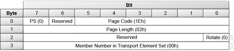
Description of the illustration ''slk_091.png''
- PS (Parameters Savable)
-
The library returns 0.
- Page Code
-
1Eh = the Transport Geometry mode page.
- Page Length
-
The number of additional types of transport geometry descriptor data to follow the header. Each descriptor has two bytes of information.
02h = The library has one transport mechanism.
- Rotate
-
0 = The library does not use multiple-sided media.
- Member Number in Transport Element Set
-
Identifies the transport element in the system.
00h = The library has one transport element.
Device Capabilities Page
-
DT — Data Transfer Element (drive)
-
I/E — Import/Export Element (CAP cells)
-
ST — Storage Element (cartridge storage cell)
-
MT — Medium transport (robot hand)
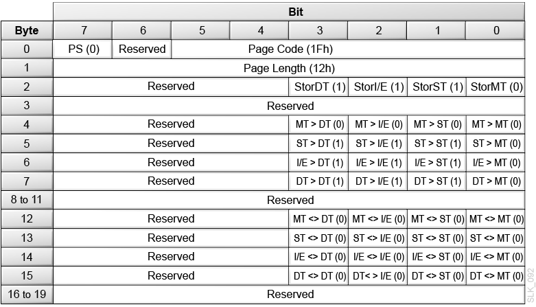
Description of the illustration ''slk_092.png''
- PS (Parameters Savable)
-
The library returns 0.
- Page Code
-
1Fh = The Device Capabilities mode page.
- Page Length
-
12h = 18 bytes of device capabilities data to follow.
- StorDT
-
1 = A tape drive can function as element storage.
- StorI/E
-
1 = A CAP cell can function as element storage.
- StorST
-
1 = A cartridge cell can function as element storage.
- StorMT
-
0 = The robot hand cannot function as element storage. You cannot use the robot as the source or destination of a move.
- MT > DT, MT > I/E, MT > ST, MT > MT, ST > MT, I/E > MT, DT > MT
-
0 = The robot hand (MT) cannot be the source or destination of a move.
- ST > DT, ST > I/E, ST > ST, I/E > DT, I/E > I/E, I/E > ST, DT > DT, DT > I/E, DT > ST
-
1 = Tape drives (DT), CAP cells (I/E), and cartridge cells (ST) are valid sources or destinations for a move.
- All <> Parameters
-
0 = The library does not support the exchange medium command.
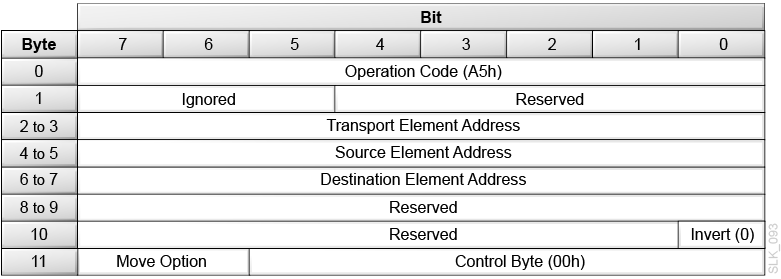
Move Medium (A5h)
Move Medium (A5h) moves a cartridge tape from one element location to another. Device Capabilities Page of the Mode Sense command provides a matrix with the valid source and destination element combinations for Move Medium.
The Fast Load option on the library controls the completion of the move command when the destination element is a tape drive. If the fast load option is disabled, the library performs the move motion and waits until the tape drive load operation completes before returning status for the move command. When the fast load option is enabled, the library performs the move motion and verifies the tape drive load starts before returning status for the move command.
Description of the illustration ''slk_093.png''
- Transport Element Address
-
00h = The default robot hand. All other values will be ignored.
- Source Element Address
-
The element address for the cartridge, which can be a storage cell, a CAP slot, or a tape drive.
- Destination Element Address
-
The element address for the cartridge move, which can be a storage cell, a CAP cell, or a tape drive.
- Invert (not supported)
-
Set this to 0.
- Move Option
-
00b = The library performs a normal move operation
01b = Not supported
10b = The library performs a mount operation with write protection enabled. This is only valid if the destination is a drive. If the drive does not support this feature or fails to acknowledge the write-protected mount option, the mount fails and the library returns the Hardware Error sense key (04) with an ASC of 40 and an ASCQ of 02 (Drive Error).
11b = The drive performs a rewind, unload, and then move operation. This option is valid only when the source element address is a drive.
Caution:
The 11b option might interfere with operations on the drive data path.
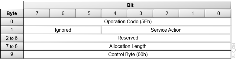
Persistent Reserve In (5Eh)
Persistent Reserve In (5Eh) returns information about active registrations or an active reservation. You can use Persistent Reserve In to help resolve contention among multiple initiators and multiple-port targets within the system.
Description of the illustration ''slk_094.png''
- Service Action
-
00h = Returns Read Keys Data
01h = Returns Read Reservation Data
02h = Returns Report Capabilities Data
03h through 1Fh are reserved.
- Allocation Length
-
Indicates the space reserved for the returned parameter list. If the length is not sufficient to contain the entire parameter list, the parameter list will be incomplete. However, a partial list is not an error
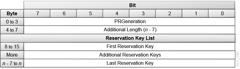
Read Keys Data
The Read Keys Data is a list of all the currently registered reservation keys.
Description of the illustration ''slk_095.png''
- PR Generation
-
A 32-bit counter that increments each time a Persistent Reserve Out command requests a Register, a Register and Ignore, a Clear, a Preempt, or a Preempt and Abort operation. The counter allows the application client to determine if another application client has changed the configuration.
A Power-On-Reset sets the counter to zero.
- Additional Length
-
The number of bytes in the reservation key list.
- Reservation Key List
-
Contains the eight-byte reservation keys registered with the library through a Persistent Reserve Out command.
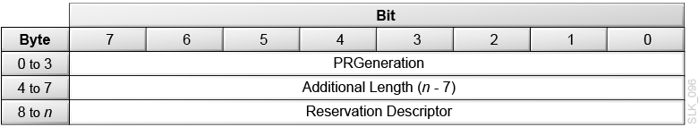
Read Reservation Data
The Read Reservation Data is a description of all currently registered reservation keys.
Description of the illustration ''slk_096.png''
- PR Generation
-
A 32-bit counter that increments each time a Persistent Reserve Out command requests a Register, a Register and Ignore, a Clear, a Preempt, or a Preempt and Abort operation. The counter allows the application client to determine if another application client has changed the configuration.
A Power-On-Reset sets the counter to zero.
- Additional Length
-
The number of bytes in the reservation descriptor list.
0 = No reservation held
16 = Active reservation data
- Reservation Descriptor
-
See Reservation Descriptor below.
Reservation Descriptor
Each persistent reservation for a logical unit has one reservation descriptor that has the format shown below.
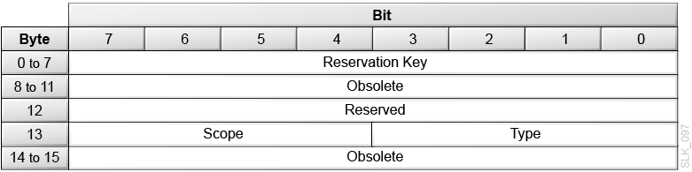
Description of the illustration ''slk_097.png''
- Reservation Key
-
The reservation key for the descriptor data that follows.
- Scope
-
Indicates whether a persistent reservation applies to an entire logical unit or to an element. The only valid value is 0h.
0h = The persistent reservation applies to the logical unit
- Type
-
3h = Exclusive access. The initiator holding the persistent reservation has exclusive access. Some commands (such as Move Medium) are only allowed for the persistent reservation holder.
6h = Exclusive Access, Registrants Only. Any currently registered initiator has exclusive access. Some commands (such as Move Medium) are only allowed for registered I_T nexuses.
Report Capabilities Data
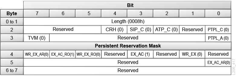
Description of the illustration ''l206_417.png''
- Length
-
The length in bytes of the parameter data.
- CRH (Compatibility Reservation Handling)
-
0 = The library processes the Reserve and Release commands as defined in SPC-2.
- SIP_C (Specify Initiator Ports Capable)
-
0 = The library does not support the SPEC_I_PT bit in the Persistent Reserve Out (5Fh) command parameter data.
- ATP_C (All Target Ports Capable)
-
0 = The library does not support the ALL_TG_PT bit in the Persistent Reserve Out (5Fh) command parameter data.
- PTPL_C (Persist Through Power Loss Capable)
-
0 = The library does not support the persist through power loss capability for persistent reservations and the APTPL bit in the Persistent Reserve Out (5Fh) command parameter data.
- TMV (Type Mask Valid)
-
0 = Ignore the persistent reservation type mask.
1 = The persistent reservation type mask field contains a bit map indicating which persistent reservation types the library supports.
- PTPL_A (Persist Through Power Loss Activated)
-
0 = The library does not support the Persist Through Power Loss Activated bit.
- WR_EX_AR (Write Exclusive-All Registrants)
-
0 = The library does not support the Write Exclusive-All Registrants persistent reservation type.
- EX_AC_RO (Exclusive Access Registrants Only)
-
1 = The library supports this persistent reservation type.
- WR_EX_RO (Write Exclusive Registrants Only)
-
0 = The library does not support the Write Exclusive-Registrants Only persistent reservation type.
- EX_AC (Exclusive Access)
-
1 = The library supports this persistent reservation type.
- WR_EX (Write Exclusive)
-
0 = The library does not support the Write Exclusive persistent reservation type.
- EX_AC_AR (Exclusive Access All Registrants)
-
0 = The library does not support the Exclusive Access-All Registrants persistent reservation type.
Persistent Reserve Out (5Fh)
Persistent Reserve Out (5Fh) uses service actions to create, manage, or remove a persistent reservation.
The application client provides a registered reservation key that identifies the initiator. An application client may use the Persistent Reserve In (5Eh) command to obtain the reservation key for the initiator holding a persistent reservation. The client may use the Persistent Reserve Out command to preempt that persistent reservation.
Note:
For more information on command processing when the library has a persistent reservation, see "Reservation Handling".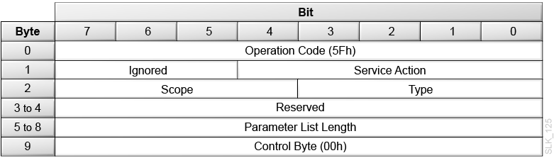
Description of the illustration ''slk_125.png''
- Service Action
-
00h = Register — registers or unregisters a reservation key.
01h = Reserve — creates a persistent reservation of the scope and type specified in Byte 2.
02h = Release — removes an active persistent reservation, if the initiator holds the persistent reservation.
03h = Clear — clears all persistent reservations for all initiators and reset all reservation keys to 0.
04h = Preempt — removes all reservations and registrations for the initiators associated with the service action reservation key in the parameter list.
05h = Preempt and Abort — Perform a Preempt action and terminate all commands by initiators associated with the cleared service action reservation key. This also clears any CAP locks and contingent allegiance in effect for these initiators.
06h = Register and Ignore Existing Key — Registers or unregisters a reservation key with the library.
- Scope
-
Indicates whether a persistent reservation applies to an entire logical unit or to an element.
0h = The persistent reservation applies to the logical unit (library or partition). This is the only valid value.
- Type
-
3h = Exclusive access. The initiator holding the persistent reservation has exclusive access. Some commands (such as Move Medium) are only allowed for the persistent reservation holder.
6h = Exclusive Access, Registrants Only. Any currently registered initiator has exclusive access. Some commands (such as Move Medium) are only allowed for registered initiators.
- Parameter List Length
-
Always 18h (24d) bytes. The parameter data for the Persistent Reserve Out command includes all fields, even when a field is not required for the specified service action.
Persistent Reserve Out Parameter List
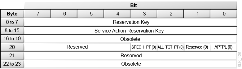
Description of the illustration ''slk_126.png''
- Reservation Key
-
An 8-byte value that identifies the initiator.
- Service Action Reservation Key
-
If the service action is Register or Register and Ignore Existing Key, this field must contain the new reservation key.
If the service action is Preempt or Preempt and Abort, this field must contain the reservation key of the persistent reservation or registration being preempted.
- SPEC_I_PT (Specify Initiator Ports - not supported)
-
Set this to 0.
- ALL_TG_PT (All Target Ports - not supported)
-
Set this to 0.
- APTPL (Activate Persist Through Power Loss - not supported)
-
Set this to 0.
Table 3-1 Persistent Reserve Out Service Actions and Parameters
| Persistent Reserve Action | Service Action | Scope | Type | Reservation Key | Service Action (SA) Res. Key | SPEC_I_PT, ALL_TG_PT, and APTPL | Unit Attention Notes |
|---|---|---|---|---|---|---|---|
|
Register a Key |
0 |
Ignored |
Ignored |
0 |
SA Key |
0 |
N/A |
|
Register a New Key |
0 |
Ignored |
Ignored |
Key |
SA Key |
0 |
N/A |
|
Unregister a Key |
0 |
Ignored |
Ignored |
Key |
0 |
0 |
See 1. |
|
Reserve: Exclusive Access |
1 |
0 |
3 |
Key |
Ignored |
Ignored |
N/A |
|
Reserve: Exclusive Access Registrants Only |
1 |
0 |
6 |
Key |
Ignored |
Ignored |
N/A |
|
Release: Exclusive Access Reservation |
2 |
0 |
3 |
Key |
Ignored |
Ignored |
N/A |
|
Release: Exclusive Access Registrants Only Reservation |
2 |
0 |
6 |
Key |
Ignored |
Ignored |
See 2. |
|
Clear: Reservation and All Host Keys |
3 |
Ignored |
Ignored |
Key |
Ignored |
Ignored |
See 3. |
|
Preempt: No Active Reservation |
4 |
Ignored |
0, 3, or 6 |
Key |
SA Key |
Ignored |
See 4. |
|
Preempt: Active Reservation |
4 |
Ignored |
3 or 6 |
Key |
SA Key |
Ignored |
See 5. |
|
Preempt and Abort: No Active Reservation |
5 |
Ignored |
0, 3, or 6 |
Key |
SA Key |
Ignored |
See 4. |
|
Preempt and Abort: Active Reservation |
5 |
Ignored |
3 or 6 |
Key |
SA Key |
Ignored |
See 5. |
|
Register and Ignore Existing Key |
6 |
Ignored |
Ignored |
Ignored |
SA Key |
Ignored |
N/A |
|
Unregister and Ignore Existing Key |
6 |
Ignored |
Ignored |
Ignored |
0 |
0 |
See 1. |
-
If the initiator unregistering the reservation key also holds a persistent reservation, then the library releases the reservation and removes the registration key. If the initiator had an Exclusive Access Registrants Only reservation, the library sends a Reservations Released Unit Attention (06h/2Ah/04h) to all other registered initiators.
-
When an initiator releases an Exclusive Access Registrants Only reservation, the library sends a Reservations Released Unit Attention (06h/2Ah/04h) to all other registered initiators.
-
When an initiator requests a Clear service action, the library clears the persistent reservation (if present) and unregisters all initiators. The library sends a Reservations Preempted Unit Attention (06h/2Ah/03h) to the other registered initiators.
Note:
You should only clear reservations for error recovery. -
When an initiator requests a Preempt or Preempt and Abort service action and there is no active persistent reservation, the library unregisters all reservation keys matching the service action key. The library sends Registrations Preempted Unit Attention (06h/2Ah/05h) to the affected initiators.
-
When an initiator requests a Preempt or Preempt and Abort service action and there is an active persistent reservation matching the service action key, the library:
-
Modifies the persistent reservation with the requesting initiator's reservation key and type. If the preempting initiator modified the persistent reservation type, the library sends a Reservations Released Unit Attention (06/2Ah/04h) all other initiators that still have a persistent registration.
-
Unregisters all other initiators with a reservation key matching the service action key and sends a Registrations Preempted Unit Attention (06h/2Ah/03h) to the affected initiators.
-
Position to Element (2Bh)
Position to Element (2Bh) moves the robot to the destination element.
Note:
The Position to Element command (2Bh) is supported only for compatibility with existing applications. The library accepts this command for compatibility, but does not perform any action.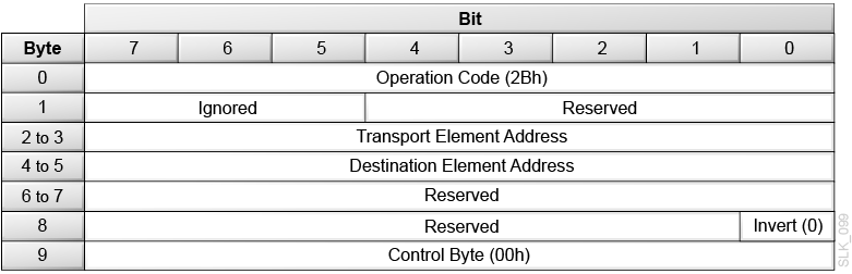
Description of the illustration ''slk_099.png''
- Transport Element Address
-
0000h = The element address of the robot.
- Destination Element Address
-
The element address of the storage cell, CAP cell, or drive. The robot positions the hand at this location.
- Invert (not supported)
-
Set this to 0.
Prevent/Allow Medium Removal (1Eh)
Prevent/Allow Medium Removal (1Eh) locks or unlocks the CAPs. The library maintains Prevent/Allow data fore each initiator:
-
If any initiator has set a Prevent state, the library locks the CAP and does not allow the CAP to open
-
If any initiator sends an Allow Media Command (Prevent bit set to 0), the library clears the Prevent bit for all hosts and allows the operator to open the CAP.
Note:
All initiators are set to an Allow state during a library power-on or after a reset.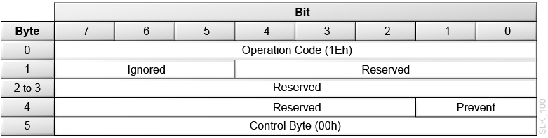
Description of the illustration ''slk_100.png''
- Prevent
-
0 = Allow — The library unlocks the CAPs, allowing an operator to open the CAP.
1 = Prevent — The library locks the CAPs.
Note:
When Prevent = 0, the library disregards device reservations and executes the command.
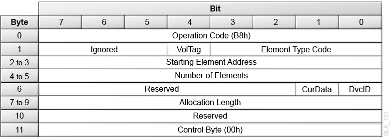
Read Element Status (B8h)
Read Element Status (B8h) returns the status of elements in the library or partition.
The library returns an eight-byte Element Status Data Header, followed by an element page (or four element pages if you set the type code to All Element Types). Each element page consists of an eight-byte Element Status Page Header, followed by the element type descriptor. Supported element type descriptors include:
-
Data Transfer Element Descriptor When DvcID = 0 (Tape Drive)
-
Data Transfer Element Descriptor When DvcID = 1 (Tape Drive)
Description of the illustration ''slk_101.png''
- VolTag
-
0 = The library does not report Volume Tag information
1 = The library reports Volume Tag information
- Element Type Code
-
0h = All Element Types
1h = Medium Transport Element (robot hand)
2h = Storage Element (cartridge cells)
3h = Import/Export Element (CAP cells)
4h = Data Transfer Element (drives)
- Starting Element Address
-
Specifies the minimum element address. The library reports elements with an element address greater than or equal to the Starting Element Address.
- Number of Elements
-
The maximum number of element descriptors to transfer. This is not an element address range.
- CurData
-
The library ignores the CurData bit and will use the robots to obtain information if needed.
0 = The library can use the robots to gather data
1 = The library will not perform mechanical operations to obtain the data
- DvcID
-
0 = The library will not return device identification information
1 = The library returns device identification information for data transfer elements.
- Allocation Length
-
The length in bytes of the space allocated by the initiator for the transfer of element descriptors. Only complete element descriptors are transferred. Data can be truncated based on the length specified in the allocation field.
Element Status Data Header
Description of the illustration ''slk_102.png''
- First Element Address Reported
-
The lowest element address found for the specified Element Type Code that is greater than or equal to the Starting Element Address.
- Number of Elements Available
-
The number of elements found for the specified Element Type Code that are greater than or equal to the Starting Element Address. This number is always less than or equal the Number of Elements specified in the CBD.
- Byte Count of Report Available
-
The number of bytes of element status data available. This count does not include the Element Status Data header bytes. The count is not adjusted to match the allocation length you specified in the Read Element Status command.
Element Status Page Header
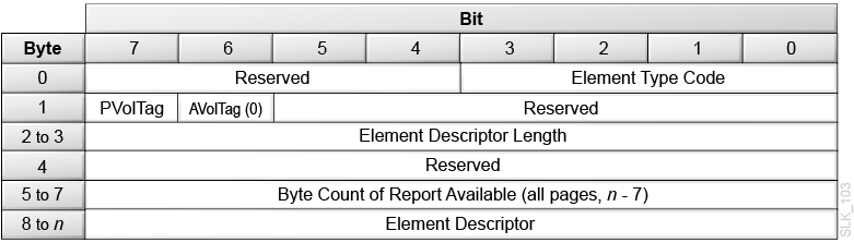
Description of the illustration ''slk_103.png''
- Element Type Code
-
1h = Medium Transport Element (robot hand)
2h = Storage Element (cartridge cells)
3h = Import/Export Element (CAP cells)
4h = Data Transfer Element (drives)
- PVolTag
-
0 = The library omits Primary Volume Tag information from the element descriptors.
1 = The library includes Primary Volume Tag information in the element descriptors.
- AVolTag
-
0 = The library does not support Alternative Volume Tags.
- Element Descriptor Length
-
The total number of bytes contained in a single element descriptor.
- Byte Count of Descriptor Data Available
-
The number of bytes of element descriptor data available. This count does not include the Element Status Page header bytes. The count is not adjusted to match the allocation length you specified in the Read Element Status command.
- Element Descriptors
-
Medium Transport Element Descriptor (Robot)
Storage Element Descriptor (Storage Slot)
Import/Export Element Descriptor (CAP slot)
Data Transfer Element Descriptor When DvcID = 0 (Tape Drive)
Data Transfer Element Descriptor When DvcID = 1 (Tape Drive)
Element Descriptors
Medium Transport Element Descriptor (Robot)
Description of the illustration ''slk_104.png''
Storage Element Descriptor (Storage Slot)
Description of the illustration ''slk_105.png''
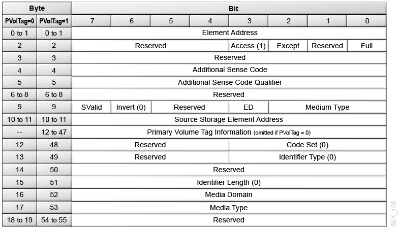
Import/Export Element Descriptor (CAP slot)
Description of the illustration ''slk_106.png''
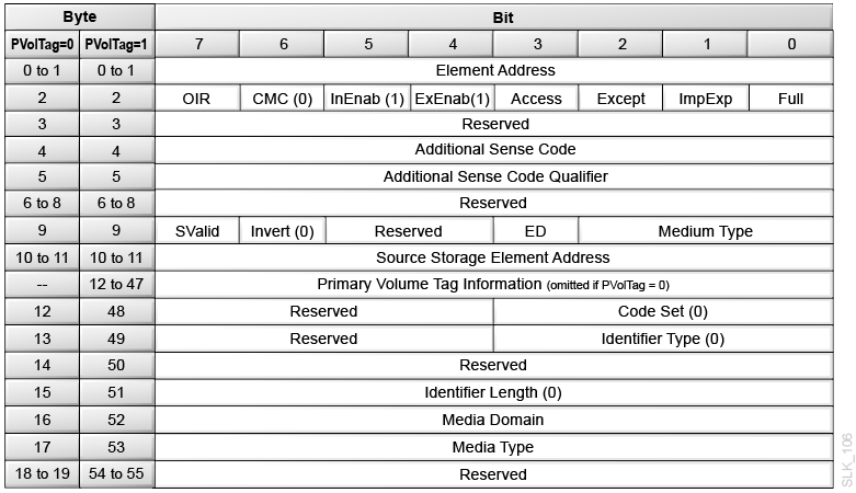
Data Transfer Element Descriptor When DvcID = 0 (Tape Drive)
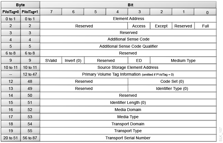
Description of the illustration ''slk_107.png''
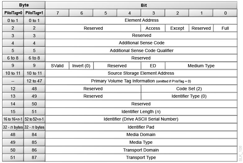
Data Transfer Element Descriptor When DvcID = 1 (Tape Drive)
Description of the illustration ''slk_108.png''
Element Descriptor Definitions
- Element Address
-
The address of the element (robot hand, storage slot, CAP slot, or drive).
- OIR
-
0 = No operator intervention required to make the CAP accessible
1 = Operator intervention required to make the CAP accessible
- CMC
-
0 = The import/export element is a CAP. The cartridge will not leave the library when prevented by the Prevent/Allow Medium Removal (1Eh) command.
- InEnab
-
1 = The CAP supports importing cartridges.
- ExEnab
-
1 = The CAP supports exporting cartridges.
- Access
-
0 = The robot cannot access the element. For Import/Export elements, this can occur when the CAP is open or a CAP magazine was removed. For Data transfer elements, this can occur when a cartridge is loaded in a drive.
1 = The robot can access the element
- Except
-
0 = The element is in a normal state
1 = The element is in an abnormal state. The Additional Sense Code (ASC) and the Additional Sense Code Qualifier (ASCQ) fields contain information regarding the abnormal state. Other fields in the descriptor might be invalid and should be ignored.
- ImpExp
-
0 = The robot placed the cartridge in the CAP for an export operation.
1 = An operator placed the cartridge in the CAP for an import operation.
- Full
-
0 = The element does not contain a cartridge
1 = The element contains a cartridge
- ASC (Additional Sense Code)
-
This field is valid only if the Except bit is set. In the case of an exception, it contains an ASC as defined for Request Sense data.
- ASCQ (Additional Sense Code Qualifier)
-
This field is valid only if the Except bit is set. In the case of an exception, it contains an ASCQ as defined for Request Sense data.
Condition ASC Value ASCQ Value CAP Open 3Ah 02h Drive Hardware Error 40h 02h - SValid
-
0 = The Source Element Address and Invert fields are not valid.
1 = The Source Element Address and Invert fields are valid.
- Invert (not supported)
-
0 = The library does not support multi-sided media.
- ED
-
0 = The element is enabled.
1 = The element is disabled (for example an open CAP or a drive hardware error).
- Medium Type
-
The type of medium currently present in the element as determined by the medium changer.
0h = Unspecified - the medium changer cannot determine the medium type.
1h = Data Medium
2h = Cleaning Medium
- Source Storage Element Address
-
This field is valid only if the SValid field is 1. This field provides the address of the last storage element this cartridge occupied. The element address value may or may not be the same as this element.
- Primary Volume Tag Information
-
When PVolTag is 1, the library returns volume tag information. When PVolTag is 0, the library omits volume tag information.
The Primary Volume Tag field contains the null-terminated ASCII barcode label on the tape cartridge. If the label on the cartridge tape is not readable or if the element is empty, the Primary Volume Tag field is filled with 36 bytes of zeros. The "Volume Label Format" controls the presentation of the volser in the Primary Volume Tag field. The library supports the following settings:
-
Left6: The left six characters of the label. If the label is "DATA01L6", then this will contain "DATA01" and the domain and type fields will contain "L" and "6".
-
ALL: The entire cartridge label. If the label is "DATA01L6", then this will contain "DATA01L6" and the domain and type fields will contain "L" and "6".
-
- Code Set
-
0h = Reserved (not supported) for the Medium Transport Element, Storage Element, Import/Export Element, or Data Transfer Element (DvcID = 0) descriptors.
2h = The identifier contains ASCII graphic codes (code values 20h through 7Eh) for Data Transfer Element (DvcID = 1) descriptor.
- Identifier Type
-
The format and assignment authority for the identifier.
0h = The library returns vendor specific data.
- Identifier Length
-
The combined length of the Identifier and the Identifier Pad.
00h = The library returns 0 bytes of identifier data in the descriptors for Medium Transport Elements, Storage Elements, Import/Export Elements, or Data Transfer Elements (DvcID = 0).
20h = The library returns 32 bytes of identifier data for the Data Transfer Element (DvcID = 1).
- Identifier (for Data Transfer Element DvcID = 1 Only)
-
The ASCII Serial Number for the tape drive associated with this data transfer element.
- Identifier Pad (for Data Transfer Element DvcID = 1 Only)
-
Contains ASCII blanks. The number of blanks depends on the length of the Identifier field. The combined length of the Identifier field and the Identifier Pad is 32 bytes.
- Media Domain
-
00h = The element contains a T9840 cartridge.
43h ('C') = The element contains a cleaning cartridge.
4Ch ('L') = The element contains an LTO cartridge.
54h ('T') = The element contains a T10000 cartridge.
FFh = The media domain cannot be determined or the element is empty.
- Media Type
-
FFh = The media type cannot be determined or the element is empty.
If the Media Domain is 00h:
-
R = The element contains a 9840 standard cartridge.
-
S = The element contains a future 9840 cartridge.
-
T = The element contains a future 9840 cartridge.
-
U = The element contains a 9840 cleaning cartridge.
-
Y = The element contains a 9840D cleaning cartridge.
If the Media Domain is 43h (C):
-
C = The element contains a T10000 Version 2 cleaning cartridge
-
L = The element contains a T10000 Universal cleaning cartridge.
-
T = The element contains a T10000 Version 1 cleaning cartridge.
-
U = The element contains a Universal LTO cleaning cartridge.
If the Media Domain is 4Ch (L):
-
1 = The element contains a 100 GB Generation 1 LTO cartridge.
-
2 = The element contains a 200 GB Generation 2 LTO cartridge.
-
3 = The element contains a 400 GB Generation 3 LTO cartridge.
-
4 = The element contains an 800 GB Generation 4 LTO cartridge.
-
5 = The element contains a 1.5 TB Generation 5 LTO cartridge.
-
6 = The element contains a 2.5 TB Generation 6 LTO cartridge.
-
7 = The element contains a 6 TB Generation 7 LTO cartridge.
-
8 = The element contains a 12 TB Generation 8 LTO cartridge.
-
T = The element contains a 400 GB Generation 3 LTO WORM cartridge.
-
U = The element contains an 800 GB Generation 4 LTO WORM cartridge.
-
V = The element contains a 1.5 TB Generation 5 LTO WORM cartridge.
-
W = The element contains a 2.5 TB Generation 6 LTO WORM cartridge.
-
X = The element contains a 6 TB Generation 7 LTO WORM cartridge.
-
Y = The element contains a 12 TB Generation 8 LTO WORM cartridge.
If the Media Domain is 54h (T):
-
1 = The element contains a T10000 Version 1 cartridge.
-
2 = The element contains a T10000 Version 2 cartridge.
-
S = The element contains a T10000 Version 1 Sport cartridge.
-
T = The element contains a T10000 Version 2 Sport cartridge.
-
- Transport Domain
-
00h = The drive supports T9840 cartridges.
4Ch (L) = The drive supports LTO cartridges.
54h (T) = The drive supports T10000 cartridges.
FFh = The element domain cannot be determined.
- Transport Type
-
FFh = The type cannot be determined.
If the Transport Domain is 00h:
-
01h = StorageTek T9840 B drive.
-
02h = StorageTek T9840 A drive.
-
03h = StorageTek T9840 A drive in 3590 emulation mode.
-
07h = StorageTek T9840 B drive in 3590 emulation mode.
-
0Bh = StorageTek T9840 C drive.
-
0Ch = StorageTek T9840 C drive in 3590 emulation mode.
-
12h = StorageTek T9840 D drive.
-
13h = StorageTek T9840 D drive in 3590 emulation mode.
-
14h = StorageTek T9840 D encryption drive.
-
15h = StorageTek T9840 D encryption drive in emulation mode.
If the Transport Domain is 4Ch (L):
-
36h = HP Generation 3 LTO drive
-
37h = IBM Generation 3 LTO drive
-
38h = Quantum Generation 3 LTO drive
-
39h = HP Generation 4 LTO drive
-
3Ah = IBM Generation 4 LTO drive
-
3Bh = HP Generation 5 LTO drive
-
3Ch = IBM Generation 5 LTO drive
-
3Dh = HP Generation 6 LTO drive.
-
3Eh = IBM Generation 6 LTO drive.
-
2Dh = IBM Generation 7 LTO drive.
-
2Eh = IBM Generation 8 LTO drive.
If the Transport Domain is 54h (T):
-
0Dh = StorageTek T10000A drive.
-
0Eh = StorageTek T10000A drive in 3590 emulation mode.
-
18h = StorageTek T10000A Encrypting drive.
-
19h = StorageTek T10000A Encrypting drive in 3590 emulation mode.
-
1Ah = StorageTek T10000B drive.
-
1Bh = StorageTek T10000B drive in 3590 emulation mode.
-
1Ch = StorageTek T10000B Encrypting drive.
-
1Dh = StorageTek T10000B Encrypting drive in 3590 emulation mode.
-
22h = StorageTek T10000C drive.
-
23h = StorageTek T10000C drive in 3590 emulation mode.
-
24h = StorageTek T10000C Encrypting drive.
-
25h = StorageTek T10000C Encrypting drive in 3590 emulation mode.
-
26h = StorageTek T10000D drive.
-
27h = StorageTek T10000D drive in 3590 emulation mode.
-
28h = StorageTek T10000D Encrypting drive.
-
29h = StorageTek T10000D Encrypting drive in 3590 emulation mode.
-
2Ah = StorageTek T10000D Fibre Channel over Ethernet.
-
2Bh = StorageTek T10000D Fibre Channel over Ethernet Encrypting drive.
-
- Transport Serial Number
-
The 32-byte ASCII serial number for the drive.
For drives with a serial number less than 32 bytes, the library left-justifies the value by returning ASCII blanks for the unused less-significant bytes. If the serial number is not available from a drive that should support an ASCII serial number, the library returns all ASCII blanks.
Release (17h)
Release (17h) releases a unit or element reservation of the library that was set using the Reserve (16h) command. Only the initiator that made the reservation can release the reservation. If another initiator attempts to release a unit reservation, the library returns Good (00h) status, but does not release the reservation. If the library has no active reservations, requesting a release does not cause an error.
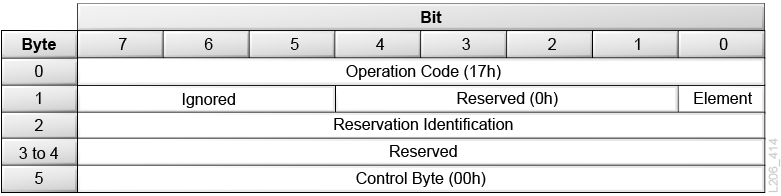
Description of the illustration ''l206_414.png''
- Element
-
0 = Releases the library or any elements that were reserved by the initiator. When this bit is set to 0, there is no need to specify the Reservation Identification field.
1 = Releases the reserved elements associated with the Reservation Identification field that was defined by this initiator.
- Reservation Identification
-
Identifies the specific element reservation to be released. This value was established by the initiator in a previous Reserve command. If an invalid Reservation Identification is specified, the library returns Check Condition (02h) status.
If the Element bit 0, the ignore this field.
Report LUNs (A0h)
Report LUNS (A0h) returns the known LUNs to which the initiator can send commands.
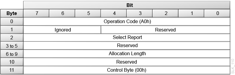
Description of the illustration ''slk_110.png''
- Select Report
-
00h = The library returns LUN addresses limited to the LUN addressing method, peripheral device addressing method, and the flat space addressing method.
02h = The library returns all LUNs accessible to the initiator.
- Allocation Length
-
The number of bytes allocated for data to be returned from the Report LUNs command.
The Allocation must be at least 16 bytes. If it is less, the library returns a check condition with the sense key set to "illegal request" and the additional sense data set to "invalid field" in the command descriptor block (CDB).
Report LUNs Data
Description of the illustration ''slk_111.png''
- LUN List Length
-
The library returns the length in bytes of the LUN list available for transfer. It is equal to 8 times the number of available logical units for the initiator.
For example: If the allocation length is 16 bytes and 2 logical units are available, this command will return the 8-byte header and 1 logical unit descriptor; however, the LUN list length will still be 16 because 16 bytes were available if the allocation length was sufficient.
- Address Method
-
00b = The library is using single level LUN addressing
- Bus ID
-
0h = There is a logical unit at the current level
- Single Level LUN Address
-
The value of the LUN.
- Second, Third, and Fourth Level LUN Address
-
00h = The library only uses single level addressing.
Report Target Port Groups (A3h)
Report Target Port Groups (A3h) returns the Target Port Group data for all ports.
Description of the illustration ''slk_112.png''
- Service Action
-
0Ah
- Allocation Length
-
The length of the parameter list the library returns. The library transfers either the number of bytes specified by the Allocation Length field or all of the available Report Target Port Group data, whichever is less.
The minimum allocation length required to return all data depends on the number of ports and port groups in the library.
-
10h (16d) = library with a one port Fibre Channel card (MPU2) installed.
-
14h (20d) = library with a two port Fibre Channel card (PUA2) installed with both ports in the Active/Optimized state.
-
1Ch (28d) = library with a two port Fibre Channel card (PUA2) installed with one port in the Active/Optimized state and the other port in the Unavailable state.
For more information on port activation, see "Behavior of Unavailable Fibre Channel Ports".
-
Target Port Group Descriptor Data
Description of the illustration ''slk_114.png''
- PREF
-
0 = The target port group is not a preferred target port
1 = The target port group is a preferred target port. All ports in the Active/Optimized group are preferred.
- Asymmetric Access State
-
0h = Active/Optimized — the ports in the group are fully operational.
3h = Unavailable — The library does not have the redundant control paths (multi-port) activation file installed.
- T_Sup
-
0 = The library does not support the transitioning asymmetric access state.
- U_Sup
-
1 = The library supports the unavailable asymmetric access state.
- S_Sup
-
0 = The library does not support the standby asymmetric access state.
- AN_Sup
-
0 = The library does not support the active/non-optimized asymmetric access state.
- AO_Sup
-
1 = The library supports the active/optimized asymmetric access state.
- Target Port Group
-
01h = Target Port Group 1
02h = Target Port Group 2
- Status Code
-
2 = The target port group asymmetric access state is altered by implicit asymmetrical logical unit access behavior.
- Target Port Group Count
-
The number of target ports that are in the target port group and the number of target port descriptors in the target port group descriptor. This can range from 1 to 2.
Target Port Descriptor Data
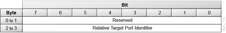
Description of the illustration ''slk_115.png''
- Relative Target Port Identifier
-
The port number. This can range from 1 to 2.
Request Sense (03h)
Request Sense (03h) returns sense data. The library generates sense data if the previous command terminated with Check Condition (02h) status. Multiple errors might occur during the processing of a single SCSI command. The sense key reflects the first error that occurred.
If you issue a Request Sense command to an unsupported LUN, the library does not return a check condition. Instead, the library returns sense data with Sense Key set to Illegal Request (05h), ASC set to LUN Not supported (25h), and ASCQ set to 00h.
If the library is partitioned and you issue a Request Sense command from an initiator that has not been configured with access, the library does not return a check condition. Instead, the library returns sense data for LUN Access not Authorized with the Sense Key set to Not Ready (02h), ASC set to 74h and ASCQ set to 71h.
If no sense data is available, the library returns sense data with the Sense Key set to No Sense (0h), ASC set to Not Additional Sense information (00h), and the ASCQ set to 00h.
The library returns Check Condition (02h) status for a Request Sense command only to report errors specific to the command itself — for example, if the library detects a nonzero reserved bit in the CDB. If the library returns a Check Condition (02h) status for a Request Sense command, the sense data might be invalid.
Description of the illustration ''slk_116.png''
- Desc
-
0 = The library will return fixed format sense data.
- Allocation Length
-
The number of bytes allocated for returned sense data. The library provides a maximum of 14h (20d) bytes of sense data.
Request Sense Data
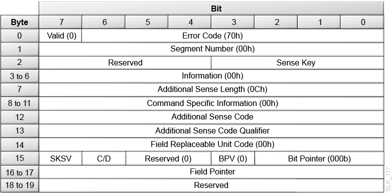
Description of the illustration ''slk_117.png''
- Valid
-
0 = The library does not return data in the Information field.
- Error Code
-
70h = The library returns only current errors.
- Segment Number
-
00h = The library does not support segment numbers.
- Sense Key
-
Describes the error, along with ASC and ASCQ. See Additional Sense Codes and Qualifiers.
0h = No Sense, indicating a successful command.
2h = Not Ready
3h = Medium Error
4h = Hardware Error
5h = Illegal Request
6h = Unit Attention
Bh = Aborted Command
- Information
-
00h = The library does not support this field.
- Additional Sense Length
-
0Ch = Indicates there are 12d bytes of additional sense bytes to follow. This value is not truncated to reflect the actual transfer length.
- Command Specific Information
-
00h = The library does not support this field.
- Additional Sense Code (ASC)
-
Describes the error. See Additional Sense Codes and Qualifiers.
- Additional Sense Code Qualifier (ASCQ)
-
Describes the error. See Additional Sense Codes and Qualifiers.
- Field Replaceable Unit Code
-
00h = The library does not support this field.
- SKSV (Sense Key Specific Valid)
-
1 = The C/D and field pointer are valid
0 = Ignore the C/D and field pointer
- C/D (Command/Data)
-
0 = The check condition status resulted from illegal parameter in the parameter list.
1 = The check condition status resulted from illegal parameter in the CDB.
- BPV (Bit Pointer Valid)
-
0 = The library does not support this field.
- Bit Pointer
-
0h = The library does not support this field.
- Field Pointer
-
The number of the byte where the error occurred. When a multiple-byte field is in error, the Field Pointer contains the value of the most significant byte of the field, which is lowest byte number. Byte numbers start at 00.
Additional Sense Codes and Qualifiers
Not Ready Sense Key (2h) Codes
The library generates a Not Ready error code if you send a command when the library is in a not ready state.
| Description | Sense Key | ASC | ASCQ |
|---|---|---|---|
| Not Ready, Cause Not Reportable | 2h | 04h | 00h |
| Not Ready, In Process of Becoming Ready | 2h | 04h | 01h |
| Not Ready, Manual Intervention Required | 2h | 04h | 03h |
| Not Ready, Logical Unit Not Accessible, Target Port In Unavailable State | 2h | 04h | 0Ch |
| Not Ready, Maintenance Mode | 2h | 04h | 81h |
| Not Ready, Cartridge Access Port Open | 2h | 3Ah | 02h |
| Not Ready, Insufficient Resources | 2h | 55h | 03h |
| Not Ready, LUN Access Not Authorized | 2h | 74h | 71h |
- Not Ready, Cause Not Reportable
-
The library detected a not ready state after execution of the command was started.
- Not Ready, In Process of Becoming Ready
-
The library is initializing and performing an audit. Initialization occurs at:
-
Power-on
-
After the door opens and closes
-
When requested from the operator panel or SLC
-
As part of a recovery during certain failures
-
- Not Ready, Manual Intervention Required
-
The library is in an inoperable state. The operator should check the user interface to determine what action is required.
- Not Ready, Logical Unit Not Accessible, Target Port in Unavailable State
-
The FC port is in an unavailable access state and has not been enabled with a hardware activation file. The port only supports a limited set of commands. See "Behavior of Unavailable Fibre Channel Ports".
- Not Ready, Maintenance Mode
-
The library was placed in maintenance mode from the operator panel or user interface.
- Not Ready, Cartridge Access Port Open
-
The library detected that the CAP is open and a SCSI command was issued to access the CAP.
- Not Ready, Insufficient Resources
-
The library was not able to complete the command. The host should reissue the command.
- Not Ready, LUN Access Not Authorized
-
The library has the partitioning activation file installed, and the host that issued the command does not have access to a partition. For more information, see "Configuring SCSI Access in a Partitioned Library".
Hardware Error Sense Key (4h) Codes
The library generates a Hardware Error if it detects a hardware or firmware error during command execution.
| Description | Sense Key | ASC | ASCQ |
|---|---|---|---|
| Hardware Error, General | 4h | 40h | 01h |
| Hardware Error, Tape Drive | 4h | 40h | 02h |
| Hardware Error, Cartridge Access Port | 4h | 40h | 03h |
| Hardware Error, Embedded Software | 4h | 44h | 00h |
| Hardware Error, Media Load/Eject Failed | 4h | 53h | 00h |
- Hardware Error, General
-
The library detected an internal electronics error during a command. This includes the electronics, vision system, and robotics of the library.
- Hardware Error, Tape Drive
-
An operation to the drive failed. The problem could be the tape drive or the interface between the library and tape drive.
- Hardware Error, CAP
-
The CAP failed.
- Hardware Error, Embedded Software
-
The embedded software that controls the SCSI interface detected an unexpected condition. This error is used for arbitrary limitations of the embedded software.
- Hardware Error, Media Load/Eject Failed
-
A cartridge mount or dismount failed to complete.
Illegal Request Sense Key (5h) Codes
Any illegal parameters in the CDB or parameter list for a particular command generates an Illegal Request sense key.
In some cases, additional information is available in Byte 15 of the sense data, which includes the sense-key-specific-value (SKSV) and command/data (C/D) fields. This information indicates the byte in the command descriptor block or the parameter list that is in error. If available, the SKSV bit in the sense data is set to 1.
| Description | Sense Key | ASC | ASCQ | SKSV |
|---|---|---|---|---|
| Parameter Length Error | 5h | 1Ah | 00h | Yes |
| Invalid Command | 5h | 20h | 00h | Yes |
| Invalid Element | 5h | 21h | 01h | No |
| Invalid Field in CDB | 5h | 24h | 00h | Yes |
| Logical Unit Not Supported | 5h | 25h | 00h | No |
| Invalid Field in Parameters | 5h | 26h | 00h | Yes |
| Invalid Release of Persistent Reservation | 5h | 26h | 04h | No |
| Incompatible Medium | 5h | 30h | 00h | No |
| Saving Parameters Not Supported | 5h | 39h | 00h | Yes |
| Medium Not Present, Drive Not Unloaded | 5h | 3Ah | 00h | No |
| Destination Element Full | 5h | 3Bh | 0Dh | No |
| Source Element Empty | 5h | 3Bh | 0Eh | No |
| Magazine Removed | 5h | 3Bh | 12h | No |
| Insufficient Resources | 5h | 55h | 03h | No |
Unit Attention Sense Key (06h) Codes
The library generates a Unit Attention sense key for all initiators if the library needs to inform the host of an asynchronous event.
| Description | Sense Key | ASC | ASCQ |
|---|---|---|---|
| Not Ready-to-Ready Transition | 06h | 28h | 00h |
| CAP Element Accessed | 06h | 28h | 01h |
| Power On Occurred | 06h | 29h | 01h |
| LUN Reset | 06h | 29h | 03h |
| Target Reset | 06h | 29h | 03h |
| Mode Parameters Changed | 06h | 2Ah | 01h |
| Reservations Preempted | 06h | 2Ah | 03h |
| Reservations Released | 06h | 2Ah | 04h |
| Registrations Preempted | 06h | 2Ah | 05h |
| Asymmetric Access State Changed | 06h | 2Ah | 06h |
| Microcode Has Been Changed | 06h | 3Fh | 01h |
| LUNs Data Has Changed | 06h | 3Fh | 0Eh |
- Not Ready to Ready Transition
-
The library transitioned to a Ready state from a Not Ready state. The library sends this unit attention to all initiators.
- CAP Element Accessed
-
The operator opened and closed the CAP. The library sends this unit attention to all initiators. You can issue a Read Element Status command to obtain an updated inventory (see "Read Element Status (B8h)").
- Power On
-
Occurs after the library powers-on, after an IPL (initial program load) from the operator panel, or after a reset over the interface. The library sends this unit attention to all initiators.
- LUN Reset
-
The library is clear of all I/O processes following the LUN reset. The library sends this unit attention to all initiators.
- Target Reset
-
The library is clear of all I/O processes following the Target reset. The library sends this unit attention to all initiators.
- Mode Parameters Changed
-
The operator added or removed elements from a partition. Send a Read Element Status (B8h) command to obtain an updated inventory. Send a Mode Sense command with Element Address page code to request the current count of each element type.
- Persistent Reservations/Registrations Preempted or Released
-
A different initiator issued a Persistent Reservation Out command that cleared the registration for this initiator or cleared a reservation that affects this initiator.
- Asymmetric Access State Changed
-
The redundant control paths (multi-port) hardware activation files was added or removed from the library. This unit attention alerts the host that the Report Target Ports Group Data has changed.
- Microcode Has Been Changed
-
The library has executed a Write Buffer command to update the functional microcode for the library.
- LUNs Data Has Changed
-
The LUN configuration for the initiator has changed. The library sends this unit attention when the operator adds or removes a LUN connection from a partition for the initiator.
Aborted Command Sense Key (0Bh) Codes
The library generates an Aborted Command error code when a SCSI command is aborted.
| Description | Sense Key | ASC | ASCQ |
|---|---|---|---|
| Mechanical Positioning Error | 0Bh | 15h | 01h |
| Initiator Detected Error | 0Bh | 48h | 00h |
| Command Phase Error | 0Bh | 4Ah | 00h |
| Data Phase Error | 0Bh | 4Bh | 00h |
| Command Overlap | 0Bh | 4Eh | 00h |
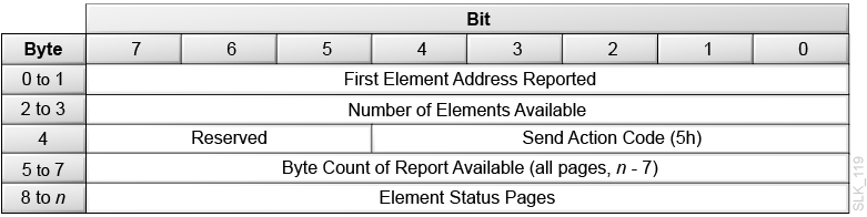
Request Volume Element Address (B5h)
Request Volume Element Address (B5h) returns the results of a previous Send Volume Tag command.
The returned data consists of an eight-byte Volume Element Address Header, followed by to four element pages (one page per element type). Each element page consists of an eight-byte Element Status Page Header, followed by the element type descriptor. Supported element type descriptors include:
-
Data Transfer Element Descriptor When DvcID = 0 (Tape Drive)
-
Data Transfer Element Descriptor When DvcID = 1 (Tape Drive)
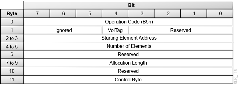
Description of the illustration ''slk_118.png''
- VolTag
-
0 = The library will not report Volume Tag information in the Element Descriptor data.
1 = The library will report Volume Tag information in the Element Descriptor data.
- Starting Element Address
-
Specifies the minimum element address. The library reports elements with an element address greater than or equal to the Starting Element Address.
- Number of Elements
-
The maximum number of element descriptors to transfer. This is not an element address range.
- Allocation Length
-
The length in bytes of the space allocated by the initiator for the transfer of element descriptors. Only complete element descriptors are transferred. Data can be truncated based on the length specified in the allocation field.
Volume Element Address Header
Description of the illustration ''slk_119.png''
- First Element Address Reported
-
The lowest element address found for the specified Element Type Code that is greater than or equal to the Starting Element Address.
- Number of Elements Available
-
The number of elements found for the specified Element Type Codes that is greater than or equal to the Starting Element Address. This number is always less than or equal the Number of Elements.
- Send Action Code
-
5h = The action code from the previous Send Volume Tag command.
- Byte Count of Report Available
-
The number of bytes of element status data available. This count does not include the Element Status Data header bytes. The count is not adjusted to match the allocation length you specified in the Read Element Status command.
- Element Status Pages
-
These pages are in the same format as the Read Element Status (B8h) command pages. See "Element Status Page Header" and "Element Descriptors".
Reserve (16h)
Reserve (16h) allows the initiator to reserve the entire library or specific elements.
Note:
For more information on command processing when the library has a Unit Reservation, see "Reservation Handling".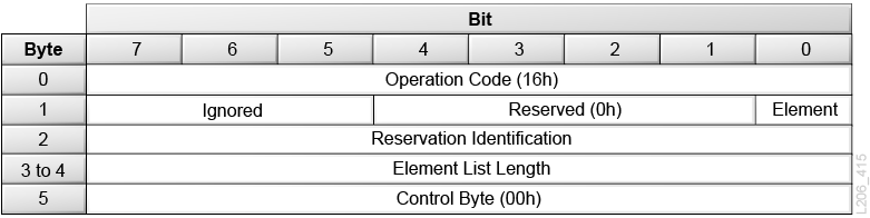
Description of the illustration ''l206_415.png''
- Element
-
0 = Reserves the entire library.
1 = Reserves a series of elements as identified by the Reservation Identification field and specified by the Element List Descriptor.
- Reservation Identification
-
A value established by the initiator to identify a specific element reservation. The library supports a maximum of 64 element reservations.
If Element bit is 0, ignore this field.
- Element List Length
-
The length in bytes of the Element List that follows the command. The list may include a maximum of 16 Element List Descriptors, each of which is six bytes long.
Valid values are 0, 6 and increments of 6 up to a maximum of 60h (96d). If set to 0 and the Element bit is 1, no elements are reserved.
If the Element bit is 0, ignore this field.
Element List Descriptor
Describes the elements reserved. The list is required if the Reserve (16h) command has the Element bit set to 1. The list consists of 0 to 16 instances of the Element List Descriptor.
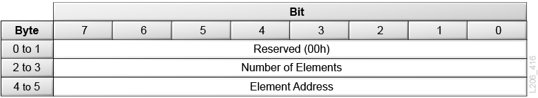
Description of the illustration ''l206_416.png''
- Number of Elements
-
The number of elements of a specific type (data cartridge slots, CAP slots, or tape drives) to be reserved. If the value of this field is 0, all elements starting at the Element Address through the last element address for that library are reserved.
- Element Address
-
The address of the element or the starting address of a series of elements to be reserved.
Send Diagnostic (1Dh)
Send Diagnostic (1Dh) requests a self-diagnostic test. The library accepts this command for compatibility, but performs no action.
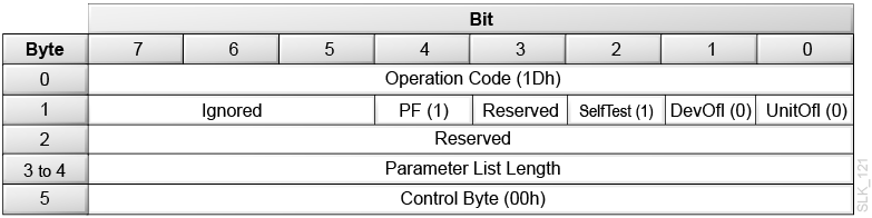
Description of the illustration ''slk_121.png''
- PF
-
1 = Page format specified by SCSI-3.
- SelfTest
-
1 = The library will run the default self test.
- DevOfl (not supported)
-
Set this to 0.
- UnitOfl (not supported)
-
Set this to 0.
- Parameter List Length
-
0h = For the default self test.
8h = For extended diagnostics (not supported).
Send Volume Tag (B6h)
Send Volume Tag (B6h) requests a VOLSER label template. The library uses the template to search for cartridges. You can send a subsequent Request Volume Element Address (B5h) command to transfer the results of this search.
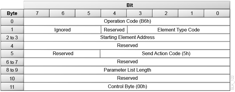
Description of the illustration ''slk_122.png''
- Element Type Code
-
0h = All Element Types
1h = Medium Transport Element (robot hand)
2h = Storage Element (cartridge cells)
3h = Import/Export Element (CAP cells)
4h = Data Transfer Element (drive)
- Starting Element Address
-
Specifies the minimum element address. The library reports elements with an element address greater than or equal to the Starting Element Address.
- Send Action Code
-
5h = The library supports the translate and search primary volume tag function.
- Parameter List Length
-
00h = No data. The library does not consider this an error.
28h = A volume identification template
Send Volume Tag Parameter List
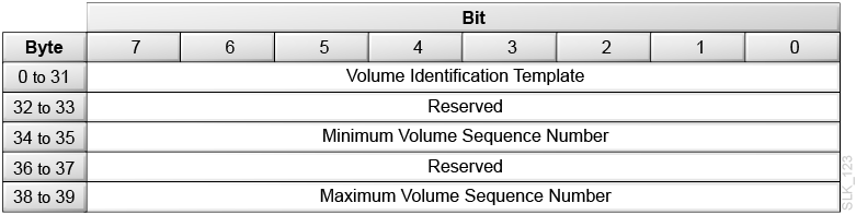
Description of the illustration ''slk_123.png''
- Volume Identification Template
-
This ASCII field specifies a volume identification search template. The first 00 hexadecimal terminates the volume identification search template. The remaining characters are set to 0.
Allowed characters are A through Z, digits 0 through 9, and special characters that include the dollar sign ($), the pound character (#), and the ASCII space character. The wild-card characters ”*” and ”?” (2Ah and 3Fh) also may be used.
- Minimum Volume Sequence Number (not supported)
-
Ignore this field.
- Maximum Volume Sequence Number (not supported)
-
Ignore this field.
Test Unit Ready (00h)
Test Unit Ready (00h) allows the initiator to determine if the library is powered on and ready to accept additional commands. This is not a request for a library self-test.
The Test Unit Ready command returns a Good (00h) status if the library is ready to accept additional commands or returns a Check Condition (02h) if the library is not ready or if there are pending Unit Attentions.
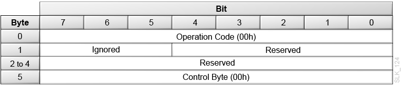
Description of the illustration ''slk_124.png''