| Oracle® Fusion Middleware Administrator's Guide for Oracle Unified Directory 11g Release 2 (11.1.2) Part Number E22648-02 |
|
|
PDF · Mobi · ePub |
| Oracle® Fusion Middleware Administrator's Guide for Oracle Unified Directory 11g Release 2 (11.1.2) Part Number E22648-02 |
|
|
PDF · Mobi · ePub |
This chapter describes the functionality that is specific to a proxy server instance, and covers the following topics:
Note:
Before you read this chapter, review Chapter 1, "Introduction to Oracle Unified Directory" for a better understanding of the concepts described here.
You can use the proxy to load balance requests across multiple data sources or replicated LDAP servers.
In a load balancing deployment, the requests are routed to one of the data sources based on the load balancing algorithm set.
You can choose one of the following load balancing algorithms:
Failover. Several remote LDAP server handle requests, based on the priority configured on a server, for a given operation type. When there is a failure, requests are sent to the server with the next highest priority for that operation type.
For more information, see Section 10.1.1, "Failover Load Balancing."
Optimal. There is no priority between the different remote LDAP servers. The LDAP server with the lowest saturation level is the one that handles the requests. The saturation level of the remote LDAP servers is regularly reevaluated, to ensure that the best route is chosen.
For more information, see Section 10.1.2, "Optimal Load Balancing."
Proportional. All the remote LDAP servers handle requests, based on the proportions (weight) set.
For more information, see Section 10.1.3, "Proportional Load Balancing."
Saturation. There is one main LDAP server that handles all requests, until the saturation limit is reached.
For more information, see Section 10.1.4, "Saturation Load Balancing."
Search Filter. Several LDAP servers are deployed, and handle requests based on certain attributes in the request search filter. For more information, see Section 10.1.5, "Search Filter Load Balancing."
In a load balancing with failover algorithm, the proxy routes requests to the remote LDAP server or data center with the highest priority for a given operation type, for example for Add operations. The proxy continues to send requests to the priority route until the remote LDAP server goes down. This may be caused by a network cut, a hardware failure, a software failure or some other problem. At failover, the proxy routes incoming requests to the server with the second highest priority for that specific operation type.
Figure 10-1 illustrates a failover load balancing configuration. In this example, there are three routes, each with a unique priority per operation type. All Add operations are treated by Server 1, since it has the highest priority, that is priority=1, while Bind operations are handled by Server 2. If Server 1 goes down, the Add requests are sent to the server with the second highest priority, that is, Server 2.
Figure 10-1 Failover Load Balancing Example
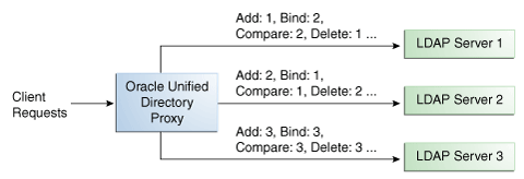
By default, the proxy does not immediately reroute requests to a server that has gone down, once it is running again. For example, if Server 1 goes down, the Add requests are sent to Server 2. Even when Server 1 is up again, Server 2 continues to handle incoming Add requests. However, if Server 2 goes down, and Server 1 is up again, Server 1 will now receive incoming requests. This default behavior can be changed with the switch-back flag. For information about configuring the switch-back flag, see Section 14.1.3.5.2, "Setting the switch-back Flag."
For failover to work effectively, the monitoring check interval must be set to be low enough so that the failover happens inside a time interval that suits your business needs. For details about setting the monitoring check interval, see Chapter 28, "Monitoring Oracle Unified Directory."
With the optimal load balancing algorithm, the proxy sends requests to the route with the lowest saturation level. The proxy continues to send requests to this route until the saturation level of the remote LDAP server on that route passes the saturation level of the other remote LDAP servers in the deployment. The saturation level is represented as a percentage.
When the saturation level of a route changes, the load balancing algorithm re-evaluates the best route and if required, selects another route as the active one. The route with the lowest saturation level is always chosen as the optimal route. In the configuration illustrated by Figure 10-5, Server 1 has the lowest saturation level and will handle all the requests until its saturation level rises above the saturation level of the other servers. If one of the servers goes down, its saturation level is considered as 100%.
Figure 10-2 Optimal Load Balancing Example
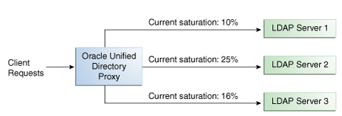
You can configure the saturation precision, to set the difference of saturation between two servers before the route changes to the server with the lowest saturation level. By default, the saturation precision is set to 5. However, if you find that the algorithm is switching between servers too often, you can set the saturation precision to 10, for example. The saturation precision is set in the LDAP server extension, see Section 14.1.3.5.3, "Setting the Saturation Precision for the Optimal or Saturation Algorithm."
The saturation level is a ratio between the number of connections in use in the connection pool and its configured maximum size. The connection pool maximum size is an advanced parameter of the LDAP server extension object.
If the number of connections in use is lower than the maximum pool size divided by 2, then the saturation is 0. This implies that the pool is not saturated.
When more than half of the connections are in use, the saturation level is calculated as follows:
100 * (1 - available connections/(max pool size/2))
This implies that the saturation level is 100 when all the connections are in use.
With the proportional load balancing algorithm, the proxy forwards requests across multiple routes to remote LDAP servers or data sources, based on the proportions set. The proportion of requests handled by a route is identified by the weight that you set for each route in your configuration. The weight is represented as an integer value.
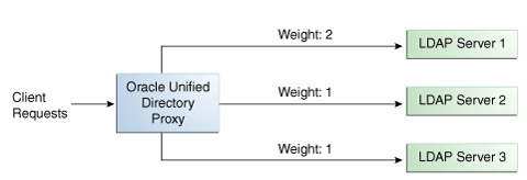
When you configure load balancing, you must indicate the proportion of requests handled by each LDAP server. In the example in Figure 10-3, Server 1 handles twice as many connections as Server 2, since the weight is set with a proportion of 2:1. Server 2 and Server 3 handle the same amount of requests (1:1).
Figure 10-3 Proportional Load Balancing Example
You can configure a specific weight for each type of client operation, as illustrated in Figure 10-4. For example, in you want Server 1 to handle all the Bind operations, this is possible. To do so, set the weight of bind to 1 (or higher) for Server 1, and to 0 for Server 2 and Server 3.
In the example illustrated in Figure 10-4, Server 1 will handle three times as many Add requests as Server 2 and Server 3. However, Server 1 will handle only one half the Search requests handled by Server 2, and Server 3. Server 2 and Server 3 will handle the same amount of Add and Search requests, but will not handle Bind requests.
Figure 10-4 Proportional Load Balancing with Request Specific Management
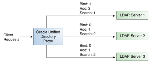
If you do not modify the weights of operations other than Bind, Add, and Search, as illustrated in Figure 10-4, the servers will share the same load for all other operations (for example for Delete operations).
For more information on configuring the load balancing weights of routes when using proportional load balancing, see Section 14.1.3.5, "Modifying Load Balancing Properties."
With the saturation load balancing algorithm, the proxy sends requests to a chosen priority route. The proxy continues to send requests to the priority route until the remote LDAP server on that route passes the saturation threshold set. The saturation threshold is represented as a percentage.
For example, if you want a remote LDAP server to manage all incoming requests, set it as priority 1. If you want that same remote LDAP server to stop handling requests when its saturation index reaches 70%, set the saturation threshold to 70%, as illustrated in Figure 10-5. In this way, the server handles all incoming requests until it becomes 70% saturated. The proxy then sends all new requests to the remote LDAP server to Server 2, since it has the next highest priority. Server 2 will continue to handle requests until it reaches its own saturation threshold, or until Server 1 is no longer saturated.
In other words, if Server 1 reaches 70% saturation, the proxy directs the requests to Server 2. If Server 1 is still at 70%, and Server 2 reaches 60%, the proxy directs the new requests to Server 3.
However, if while Server 2 is handling requests, the saturation level of Server 1 drops to 55%, the proxy will direct all new requests to Server 1, even if Server 2 has not reached its saturation threshold.
Figure 10-5 Saturation Load Balancing Example
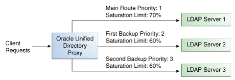
If all routes have reached their saturation threshold, the proxy chooses the route with the lowest saturation.
You can set a saturation threshold alert that warns you when a server reaches its saturation limit. For example, if you set a saturation threshold alert to 60%, you will receive a notification when the server reaches this limit, and you can act before the server becomes too degraded.
For more information about how to determine the saturation level, see Section 10.1.2.1, "Determining Saturation Level."
With the search filter load balancing algorithm, the proxy routes search requests to LDAP servers based on the presence of certain attributes defined in the request search filter.
The topology consists of several LDAP servers that are accessible through the proxy. All the LDAP servers contain similar data, but each server is optimized based on attributes defined in the search filter to provide better performance. You can configure each route with a list of allowed attributes and a list of prohibited attributes. A search request matches a route when the request search filter contains at least one allowed attribute, and none of the prohibited attributes.
The Figure 10-6 illustrates a search filter load balancing algorithm. In this example, there are three LDAP servers and therefore three distinct routes. LDAP server 1 indexes the uid attribute, LDAP server 2 indexes the cn attribute, and the third LDAP server is a pass-through route.
When the proxy receives a search request that contains the uid attribute in its search filter, the search request is routed to LDAP server 1 for better performance. Similarly, if the search filter contains a cn attribute, then the search request is routed to LDAP server 2. All other search requests are routed to the pass-through LDAP server 3.
All other requests, such as ADD, DELETE, MODIFY, and so on can be routed to any LDAP server based on the highest priority. Each search filter route is given a priority. This priority determines the order in which the route are evaluated. The highest priority route filter that matches the search filter is selected to process the request. If all the search filter routes have the same priority, then any route can process the request.
The Oracle Unified Directory distribution feature addresses the challenge of large deployments, such as horizontal scalability, where all the entries cannot be held on a single data source, or LDAP server. Using distribution can also help you scale the number of updates per second.
In a distribution deployment, you must first split your data into smaller chunks. To split the data, you can use the split-ldif command. These chunks of data are called partitions. Typically, each partition is stored on a separate server.
The split of the data is based on one of the following distribution algorithms:
Numeric. Entries are split into partitions and distributed based on the numeric value of the naming attribute (for example uid). See Section 10.2.1, "Numeric Distribution" for more information.
Lexico. Entries are split into partitions and distributed based on the alphabetical value of the naming attribute (for example cn). See Section 10.2.2, "Lexico Distribution" for more information.
Capacity. Entries are added to a partition based on the capacity of each partition. This algorithm is used for Add requests only. All other requests are distributed by the global index catalog or by a broadcast. See Section 10.2.3, "Capacity Distribution" for more information.
DN pattern. Entries are split into partitions and distributed based on the pattern (value) of the entry DN. See Section 10.2.4, "DN Pattern Distribution" for more information.
The type of data distribution you choose will depend on how the data in your directory service is organized. Numeric and lexico distribution have a very specific format for distribution. DN pattern can be adapted to match an existing data distribution model.
If a client request (except Add) cannot be linked to one of the distribution partitions, the proxy broadcasts the incoming request to all the partitions, unless a global index catalog has been configured.
However, if the request is clearly identified as outside the scope of the distribution, the request is returned with an error indicating that the entry does not exist. For example, if the distribution partitions includes data with uid's from 1-100 (partition1) and 100-200 (partition2) but you run a search where the base DN is uid=222,ou=people,dc=example,dc=com, the proxy will indicate that the entry does not exist.
Moreover, for the numeric and lexico algorithms, it is the first RDN after the distribution base DN that is used to treat a request. For example, the following search will return an error, as the uid is not the first RDN after the distribution base DN, for example ou=people,dc=example,dc=com.
$ ldapsearch -b "uid=1010,o=admin,ou=people,dc=example,dc=com" "objectclass=*"
Consider the number of partitions carefully. When you define the number of partitions you want in your deployment, you should note that you cannot split and redistribute the data into new partitions without downtime. You can, however, add a new partition with data that has entries outside the initial ones.
For example, if the initial partitions cover data with uids from 1-100 (partition1) and 100-200 (partition2), you can later add a partition3 which includes uids from 200-300. However, you cannot easily split partition1 and partition2 so that partition1 includes uids 1-150 and partition2 includes uids 150-300, for example. Splitting partitions is essentially like reconfiguring a new distribution deployment.
With a distribution using numeric algorithm, the proxy forwards requests to one of the partitions, based on the numeric value of the first RDN after the distribution base DN in the request. When you set up distribution with numeric algorithm, you split the data of your database into different partitions based on a numerical value of the attribute of your choice, as long as the attribute represents a numerical string. The proxy then forwards all client requests to the appropriate partition, using the same numeric algorithm.
For example, you could split your data into two partitions based on the uid of the entries, as illustrated in Figure 10-7.
In this example, a search for an entry with a uid of 1111 is sent to Partition 1, while a search for an entry with a uid of 2345 is sent to Partition 2. Any request for an entry with a uid outside the scope of the partitions defined will indicate that no such entry exists.
Note:
The upper boundary limit of a distribution algorithm is exclusive. This means that a search for uid 3000 in the example above returns an error indicating that the entry does not exist.
Example 10-1 Examples of Searches Using Numeric Distribution Algorithm
The following search will be successful:
$ ldapsearch -b "uid=1010,ou=people,cn=example,cn=com" "cn=Ben"
However, the following searches will indicate that the entry does not exist (with result code 32):
$ ldapsearch -b "uid=1010,o=admin,ou=people,cn=example,cn=com" "objectclass=*"

$ ldapsearch -b "uid=99,ou=people,cn=example,cn=com" "objectclass=*"
The following search will be broadcast, as the proxy cannot determine the partition to which the entry belongs, using the distribution algorithm defined above:
$ ldapsearch -b "ou=people,cn=example,cn=com" "uid=*"
With a distribution using lexico algorithm, the proxy forwards requests to one of the partitions, based on the alphabetical value of the first RDN after the distribution base DN in the request. When you set up distribution with lexico algorithm, you split the data of your database into different partitions, based on an alphabetical value of the attribute of your choice. The proxy then forwards all client requests to the appropriate partition, using the same algorithm.
For example, you could split your data into two partitions based on the cn of the entries, as illustrated in Figure 10-8.
In this example, any requests for an entry with a cn starting with B such as Ben are sent to Partition 1, while requests for an entry with a cn from M-Y are sent to Partition 2.
Note:
The upper boundary limit of a distribution algorithm is exclusive. This means that a search for cn= Zachary in the example above will indicate that no such entry is found. In order to include entries starting with Z in the search boundaries, then you should use the unlimited keyword. For example, cn=[M..unlimited[will include all entries beyond M.
Example 10-2 Examples of Searches Using Lexico Distribution Algorithm
The following search will be successful:
$ ldapsearch -b "cn=Ben,ou=people,cn=example,cn=com" "objectclass=*"
The following search will also be successful, as cn=Ben is the first RDN.
$ ldapsearch -b "uid=1010,cn=Ben,ou=people,cn=example,cn=com" "objectclass=*"
However, the following searches will indicate that the entry does not exist (with result code 32):
$ ldapsearch -b "cn=Ben,o=admin,ou=people,cn=example,cn=com" "objectclass=*"

$ ldapsearch -b "cn=Zach,ou=people,cn=example,cn=com" "objectclass=*"
The distribution cannot determine to which partition the following search belongs and will be broadcast:
$ ldapsearch -b "ou=people,cn=example,cn=com" "cn=*"
With a capacity-based distribution, the proxy sends Add requests based on the capacity of each partition, which is determined by the maximum number of entries the partitions can hold. All other requests are distributed by the global index catalog or by broadcast.
Because the data is distributed to the partitions in a completely random manner, the easiest way to identify on which partition a particular data entry is by using a global index. Global index is mandatory when using capacity distribution. If no global index is set up, all requests other than Add will have to be broadcast. For more information about global indexes, see Section 10.3, "Global Index Catalog" and Section 14.1.6, "Configuring Global Indexes By Using the Command Line."
Figure 10-9 Capacity Distribution Example
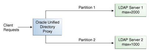
In the example illustrated in Figure 10-9, Partition 1 has twice the capacity of Partition 2, therefore Partition 1 will receive twice the add requests sent to Partition 2. This way, both partitions should be full at the same time. When all the partitions are full, the distribution will send one request to each partition at each cycle.
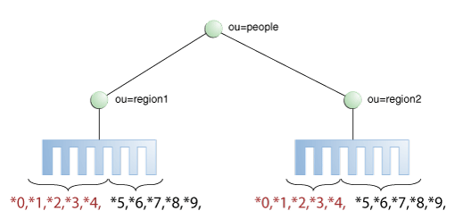
With a distribution using DN pattern algorithm, the proxy forwards requests to one of the partitions, based on the match between a request base DN and a string pattern. The match is only perform on the relative part of the request base DN, that is, the part after the distribution base DN. For example, you could split your data into two partitions based on a the DN pattern in the uid of the entries, as illustrated in Figure 10-10.
Distribution using DN pattern is more onerous than distribution with numeric or lexico algorithm. If possible, use another distribution algorithm.
Figure 10-10 DN Pattern Distribution Example

In this example, all the data entries with a uid that ends with 0, 1, 2, 3, or 4 will be sent to Partition 1. Data entries with a uid that ends with 5, 6, 7, 8, or 9 will be sent to Partition 2.
This type of distribution, although using numerical values is quite different from numeric distribution. In numerical distribution, the data is partitioned based on a numerical range, while DN pattern distribution is based on a pattern in the data string.
Distribution using a DN pattern algorithm is typically used in cases where the distribution partitions do not correspond exactly to the distribution base DN. For example, if the data is distributed as illustrated in Figure 10-11, the data for Partition 1 and Partition 2 is in both base DN ou=people,ou=region1 and ou=people,ou=region2. The only way to distribute the data easily is to use the DN pattern.
Figure 10-11 Example of Directory Information Tree
Example 10-3 Example of DN Pattern Algorithm Split by Region
If the deployment of the information is based in two geographical locations, it may be easier to use the DN pattern distribution to distribute the data. For example, if employee numbers were 4 digit codes, where the first digit indicated the region, then you could have the following:
| Region 1 | Region 2 |
|---|---|
|
1000 |
2000 |
|
1001 |
2001 |
|
1002 |
2002 |
|
1003 |
2003 |
|
1004 |
2004 |
|
1005 |
2005 |
|
1006 |
2006 |
|
1007 |
2007 |
|
1008 |
2008 |
|
1009 |
2009 |
|
1010 |
2010 |
|
... |
... |
In order to spread the load of data, the entries in each location are split over two servers, where Server 1 contains all entries that end with 0, 1, 2, 3, and 4, while Server 2 contains all the entries that end with 5, 6, 7, 8, and 9, as illustrated in Figure 10-10.
Therefore, a search for DN pattern 1222 would be sent to partition 1, as would 2222.
A global index catalog can be used with a distribution deployment. If you are configuring a capacity based distribution, you must have a global index, with DN indexed. The global index catalog maps the entries to the distribution partition in which the data is held. When the proxy receives a request from the client, the distribution looks up the attribute entry in the global index catalog, and forwards the client request to the correct partition. This diminishes the need for broadcasts. Moreover, if a modify DN request is made, the global index catalog will ensure that the entry is always found.
A global index catalog maps the entries based on specific attributes, such as employee number or telephone number. The value of the attribute to be indexed must be unique across all the entries. You cannot use a global index to map entries based on country, for example, as that information is not unique.
If you index an attribute whose values are not unique, the proxy server might be unable to return all the requested entries. Say, for example, that you index the mail attribute, whose values are not necessarily unique. You now add the following two entries in sequence:
Entry 1, with uid=user.1 and mail=joe.smith@example.com is sent to partition 1.
Entry 2, with uid=user.2 and mail=joe.smith@example.com is sent to partition 2.
In this situation, the global index mail keeps reference to the second entry only. A search with the filter (mail=joe.smith@example.com) will return only the second entry, uid=user.2.
A global index catalog can include several global indexes. Each global index maps a different attribute. For example, you can have one global index catalog called GI-catalog, which includes a global index mapping the entries based on the telephone number and one mapping the entries based on the employee number. This means that you can forward client requests to the right partition using either the telephone number or the employee number.
Global index catalogs and global indexes are created and configured using the gicadm command. For more information see Section 14.1.6, "Configuring Global Indexes By Using the Command Line" and Appendix A, "gicadm."
The global indexes can be populated with data from LDIF files. The data from one LDIF file can be split into partitions using the split-ldif command. For more information, see Appendix A, "split-ldif."
A global index catalog should be replicated to avoid a single point of failure. For information on replicating the global index catalog, see Section 14.1.6.2, "Replication of Global Index Catalogs."
Example 10-4 Using a Global Index Catalog for Telephone Numbers
A typical example of a unique attribute which can be used to create a global index is a telephone number: the value of the attribute is unique, that is, only one person (employee, for example) can have that telephone number.
In the example below, the entries in the database have been split based on the telephone number. The global index includes the following information:
| Value | Partition ID |
|---|---|
|
4011233 |
1 |
|
4011234 |
1 |
|
7054477 |
2 |
The global index does not store the name of the employees, location, and other attribute values that may be associated to the telephone number. It only maps the attribute indexed to the partition. The data associated to the indexed value (here telephone number) is stored in the remote LDAP server.
If an employee has multiple phone numbers, these are regarded as multi-valued entries. In this case, if the global index is created based on the telephone number, there will be two global index entries that will result in finding one employee, say Ben Brown.
In the example above, employee Ben Brown could have both telephone number 4011233 and 7054477 assigned to him. In this case, a search on one of Ben Brown's telephone number would return the correct partition, and all the information associated to the telephone number, including the name Ben Brown, regardless that he has two phone numbers attributed to him.
Each entry in a directory is identified by a DN and a set of attributes and their values. Sometimes, the DN and the attributes defined on the client side do not map with the DN and the attributes defined on the server side. For instance, an organization, Example A contains dc=parentcompany, dc=com entries. It acquires another organization, Example B. Example B contains dc=newcompany, dc=com entries. Therefore, dc=newcompany, dc=com must be renamed to dc=parentcompany, dc=com for the existing client applications to work correctly.
You can define a DN renaming workflow element to rename DNs to values that match the server side. When a client makes a request, the DNs and attributes are renamed to match those in the server. When the result is returned to the client, the DN and attributes are changed back to match what the client has requested.
Oracle Unified Directory provides a DN renaming workflow element that allows you to transform the content of a Directory Information Tree (DIT) into another DIT with a different base DN. When an operation (Add, Bind, Delete, Modify, and so on) goes through a DN renaming workflow element, its parameters are transformed according to the DN renaming configuration to transform the virtual entries into real entries.
Figure 10-12 illustrates how DN renaming is performed using the proxy.
The client expects ou=myorg, dc=server, dc=com entries. However, the LDAP server contains ou=people, dc=server, dc=com entries. The proxy renames the DNs by making use of the DN renaming workflow element.
In this example, the real entries ou=people, dc=server, dc=com are seen as ou=myorg, dc=server, dc=com entries from the client side.
The DN renaming transformation is applicable to the following objects:
DN of the entry: For example, the real entry on the LDAP server dn:uid=user, ou=people, dc=server, dc=com is transformed into a virtual entry dn:uid=user, ou=myorg, dc=server, dc=com from the client perspective.
Attributes of the entry that contain DNs: For example, the server-side value of the manager attribute of an entry with an objectclass inetorgpersonmanager: manager:uid=mgr, ou=people, dc=server, dc=com is transformed into the value manager:uid=mgr, ou=myorg, dc=server, dc=com on the client side.
Note:
You can apply the transformation to all the user attributes of the entries, define a restricted list of attributes to which the operation applies, or define a restricted list of attributes to which the operation does not apply.