 DataStage Designer Overview
This chapter provides an overview of DataStage Designer and discusses how to:
Manage Repository Objects
Edit Object Properties
Import and Export Repository Components
Use Table Definitions
Build DataStage Jobs
Use Database and File Stages
Add and Link Stages
Compile and Run Jobs
Edit Job Properties
Use Expressions
Create Constraints
Use Hashed File Stages
Use Job Sequencers
Use DataStage BASIC
Note. This chapter does not discuss all the features available for DataStage Designer. For a complete view of DataStage Designer functionality, please see the delivered IBM WebSphere documentation.
DataStage Designer Overview
The DataStage Designer is the primary interface to the metadata repository and provides a graphical user interface that enables you to view, edit, and assemble DataStage objects from the repository needed to create an ETL job.
An ETL job should include source and target stages. Additionally, your server job can include transformation stages for data filtering, data validation, data aggregation, data calculations, data splitting for multiple outputs, and usage of user-defined variables or parameters. These stages allow the job design to be more flexible and reusable.
DataStage Designer enables you to:
Create, edit, and view objects in the repository.
Create, edit, and view data elements, table definitions, transforms, and routines.
Import and export DataStage components, such as projects, jobs, and job components.
Analyze the use of particular items in a project.
Edit and view user-defined object properties.
Create jobs, job sequences, containers, and job templates.
Create and use parameters within jobs.
Insert and link stages into jobs.
Set stage and job properties.
Load and save table definitions.
Save, compile, and run jobs.
DataStage Designer Window
The DataStage Designer window, which is the graphical user interface used to view, configure, and assemble DataStage objects, contains the following components:
Repository Window: Displays project objects organized into categories. By default, the Repository window is located in the upper left corner of the Designer window. The project tree displays in this pane and contains the repository objects belonging to a project.
Tool Palette: Contains objects that you add to your job design, such as stage types, file types, database types, and processor objects. You can drag these objects from the Palette into the Diagram window. By default, this window is displayed in the lower left corner, of the Designer window. This window appears to be empty until you open or create a job.
Diagram Window: Serves as the canvas for your job design. You drag, drop, and link stages and processor objects to create jobs, sequencers, and templates.
Property Browser: Displays the properties of the currently selected stage of the job that is open in the Diagram window. By default, this window is hidden. To open it, select View, Property Browser from the menu bar, and then click a stage to see its properties.
The following diagrams show the layout of the DataStage Designer window components:
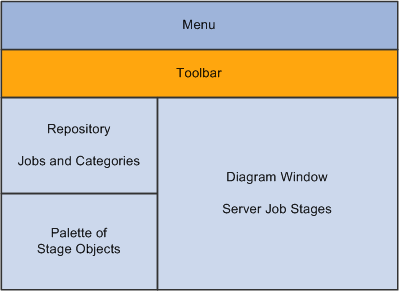
DataStage Designer Window - Layout View
The display area is in the right pane of the DataStage Designer window and displays the contents of a chosen object in the project tree.
By Default, the Designer window contains the Repository window, Tool Palette, and Diagram window. You can optionally view the Property Browser by selecting View, Property Browser from the menu bar .
The display of Designer windows and toolbars can be shown or hidden by selecting the appropriate option from the View menu. You can dock, undock, or rearrange the Designer windows.
Designer Menus
Most Designer menu items are also available in the toolbars. The following are some additional options that are available through the menus:
|
Designer Menu Item |
Description |
|
View, Customize Palette |
Customize your palette. |
|
View, Property Browser |
Enables you to view and edit properties of a DataStage object. |
|
Import |
Enables you to import ETL projects, jobs, or other components that you export from another system, as well as DataStage components, such as table definitions, from text files or XML documents. |
|
Export |
Enables you to export DataStage objects in the form of text files with the file extension .dsx. |
|
Tools, Run Multiple Job Compile |
Enables you to compile all your jobs at the same time. |
|
Tools, Run Director |
Invoke the Director module, and log you into your project automatically. |
Designer Toolbar
The Designer toolbar displays the following buttons:
This table describes the Designer toolbar buttons:
|
Designer Toolbar Button |
Description |
|
New |
Open the New window where you can open a new DataStage object. |
|
New (arrow down button) |
Display options associated with the New command on the toolbar. |
|
Open |
Display the Open window that enables you to open an existing or recently opened repository object. |
|
Save |
Save the current job or container. |
|
Save All |
Save all open jobs or containers. |
|
Job Properties |
Open the Job Properties window for the current job open in the Diagram window. |
|
Cut |
Cut a specific object or text and temporarily stores it. |
|
Copy |
Copy a specific object or text and temporarily stores it. |
|
Paste |
Paste the temporarily stored object or text. |
|
Undo |
Undo the last task performed. |
|
Redo |
Redo the last task performed. |
|
Quick Find |
Search for DataStage objects using the quick find feature. |
|
Advanced Find |
Search for DataStage objects using the advanced find feature. |
|
Data Flow Analysis |
Use this function to display the data lineage for a column definition to see where in the job design that the column definition is used, display the source of the data for selected column or columns, display the target for the data for selected column or columns. |
|
Construct Local Container |
Create a local job container. |
|
Construct Shared Container |
Create a shared container reusable by other jobs. |
|
Compile |
Compile the current job. |
|
Run |
Run the current job. |
|
Grid Lines |
Show or hide a grid in the Diagram window. |
|
Link Markers |
Show or hide markers on the links. |
|
Toggle Annotations |
Show or hide annotations in the diagram window. You enter annotations by dragging the Annotation object from the Palette. |
|
Stage Validation errors |
See visual cues for parallel jobs or parallel-shared containers. The visual cues display compilation errors for every stage on the canvas, without you having to actually compile the job. The option is enabled by default |
|
Snap to Grid |
When the grid is shown and Snap to Grid is enabled, align objects that you drag with the grid. |
|
Zoom In |
Magnify the diagram display. |
|
Zoom Out |
Shrink the diagram display. |
|
|
Print the current diagram window. |
|
Generate Report |
Generate an HTML report of a server, parallel, or mainframe job or shared container. You can view this report in a standard Internet browser. |
|
Help on View |
View context-sensitive help. |
Debug Toolbar
The Debug toolbar provides basic functions for testing and troubleshooting your jobs.
The Debug toolbar can be accessed by selecting View, Debug and displays the following buttons:
This table describes the Debug toolbar buttons:
|
Debug Toolbar Button |
Description |
|
Set target debug job |
Enables you to select the job you want to debug. |
|
Start/Continue Debugging |
Start or stop running in debug mode. |
|
Next Link |
Run the job until you come to the next link. |
|
Next Row |
Run until you get to the next row. |
|
Stop Job |
Stop the job run. |
|
Set debug Job Parameters |
Set job parameters. |
|
Edit Breakpoints |
Change breakpoints (pauses that you have inserted into the run). |
|
Toggle Breakpoints |
Enable or disable breakpoints. |
|
Clear All Breakpoints |
Clear breakpoints. |
|
View Job Log in Director |
Open the job log in the Director module. |
|
Show/Hide Debug Window |
Display or hide the debug window. |
All of the Debug toolbar options are also available from the Debug menu.
Managing Repository Objects
You can use DataStage Designer to view job categories, which serve to organize repository objects.
You can view the following repository objects within a job category:
Data Elements.
Jobs.
Routines.
Shared Containers.
Stage Types.
Table Definitions.
Transforms.
You can also create new repository objects:
You can also copy, rename, edit, delete, or move an item using the File menu commands or the item level shortcut menu.
Editing Object Properties
Object properties consist of descriptive information and other types of information, depending on the object type.
Using DataStage Designer you can:
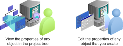
DataStage Designer - Object Properties
The following is an example of an object property for the String data element:
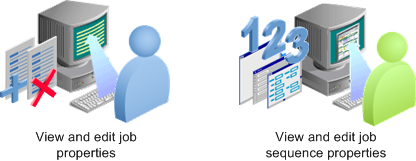
 Editing Job and Job Sequence Properties
DataStage Designer enables you to:
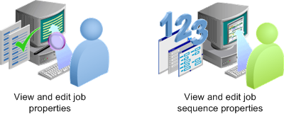
DataStage Designer - Job/Job Sequence Properties
The following is an example of a server job property:
Editing Server RoutinesYou can create, edit, or view server routines using the Routine window. Argument names in built-in routines cannot be changed.
The following components are classified as routines:
Transform functions.
Before/after subroutines.
Custom UniVerse functions.
ActiveX (OLE) functions.
Editing the Stage TypeThe Stage Type category in the project tree contains all the stage types that you can use in your jobs. Properties of WebSphere DataStage's pre-built stages are read-only.
You can create or edit object properties for the following stage types:
Custom Plug-in Stages.
Parallel Job Custom Stages.
DataStage Designer enables you to create and register plug-in stages to perform specific tasks that the built-in stages do not support. You need to register custom plug-in stages before you can use them. In addition, DataStage Designer enables you to create custom parallel stage types.
Specifying Table DefinitionsDataStage Designer enables you to:
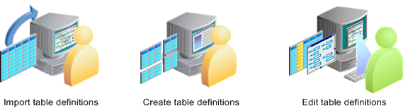
DataStage Designer - Table Definitions
Table definitions:
Specify the data structure used by each stage in a DataStage job.
Are stored in the repository and are shared by all jobs in a project.
Are required for each data source and data target.
Can be imported, manually created, or edited.
Importing and Exporting Repository Components
Using the DataStage Designer import and export facilities enable you to move jobs or other components between projects. You can also move projects, jobs, or components from one system to another. In addition, you can import components from text files or XML documents, and you can export to XML documents. XML documents can be used as a convenient way to view descriptions of repository objects using a web browser.
Importing
The DataStage Designer import facility enables you to import:
ETL projects, jobs, or other components that you export from another system.
DataStage components, such as table definitions, from text files or XML documents.
You can use the Import facility to import table definitions from a variety of file types, including sequential files, ODBC, and XML.
Exporting
The DataStage Designer export facility enables you to export:
ETL projects, jobs, or other components.
Jobs or other components to XML documents.
Job executables.
Package server jobs using the Packager Wizard.
When you export projects or components, by default they are stored in text files with the file extension .dsx. You can also export to XML files by selecting the appropriate check box in the Export window. You also have the option to append the exported items to an existing file.
Using Table Definitions
Table definitions are:
DataStage components that specify the metadata used at each stage of a job.
Stored in the Repository.
Shared by all the jobs in a project.
You need a table definition for each data source stage or data target stage you use in your job. You can import, create, or edit a table definition using DataStage Designer.
Creating Table DefinitionsTo create a new Table Definition, select New Table Definition from the Table Definition menu. The Table Definition window appears:
The Table Definition window has these tabs:
General
The General tab contains the data source type, data source name, table or file name, and other general information about the table definition.
Columns
The Columns tab contains a grid displaying the column definitions for each field in the table definition.
Format
The Format tab contains file format parameters for sequential files used in DataStage jobs
Relationships
The Relationships tab displays the details of any relationship this table definition has with other tables, and allows you to define new relationships.
NLS
If NLS is enabled, the NLS tab is enabled and contains the name of the map to use for the table definition.
Layout
The Layout tab displays the schema format of the column definitions in a table.
Locator
Using the Locator tab you can view and edit the data resource locator associated with the table definition. The data resource locator is a property of the table definition that describes the real world object from which the table definition was imported. The labels and contents of the fields in this window depend on the type of data source or target from which the locator originates.
Analytical Information
The Analytical Information tab displays information about the table definition generated by Information Analyzer.
Parallel
The Parallel tab displays detailed format information for the defined metadata for parallel jobs.
Importing Table DefinitionsYou can directly import a table definition from a source or target database. You can import table definitions from ODBC data sources, plug-in stages, UniVerse tables, hash files, UniData files, or sequential files.
In the DataStage Designer Repository window, right-click on Table Definitions. Select Import.
You can select the type of table definition data source from the available options.
Building DataStage Jobs
DataStage provides these types of jobs:
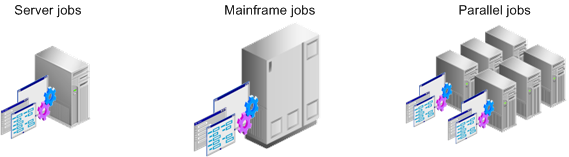
DataStage Jobs
Server Jobs: Run on the DataStage Server.
Mainframe Jobs: Available only if you have installed Enterprise MVS Edition and uploaded it to a mainframe, where they are compiled and run.
Parallel Jobs: Available only if you have installed the Enterprise Edition and run on DataStage servers that are SMP, MPP, or cluster systems.
The following is an example of one of the delivered Campus Solutions Warehouse server jobs:
Perform the following steps to build a job:
Define optional project-level environment variables in DataStage Administrator.
Define optional environment parameters.
Import or create table definitions, if they are not already available.
Add stages and links to the job to indicate data flow.
Edit source and target stages to designate data sources, table definitions, file names, and so on.
Edit transformer and processing stages to perform various functions, include filters, create lookups, and use expressions.
Save, compile, troubleshoot, and run the job.
Using Database and File Stages
Database stages represent data sources or data targets.
DataStage provides three types of stages:
Server Job Database Stages
Server Job File Stages
Dynamic Relational Stages
Processing Stages
Each stage has a set of predefined and editable properties.
Server Job Database StagesThe following are some of the delivered server job database stages:
ODBC
UniVerse
UniData
Oracle
Sybase
Server Job File StagesThe delivered server job file stages are:
Sequential file
Hashed file
Complex flat file
Folder
Dynamic Relational StagesDynamic Relational Stages (DRS):
Read data from any DataStage stage.
Read data from any supported relational database.
Write to any DataStage stage.
Write to any supported relational database.
PeopleSoft-delivered ETL jobs use the DRS stage for all database sources or targets. This is represented in the Database group as "Dynamic RDBMS." When you create jobs, it is advisable to use the DRS stage rather than a specific type such as DB2 because a DRS will dynamically handle all of PeopleSoft supported database platforms.
The following example shows a DRS database stage in a delivered Campus Solutions Warehouse job:
A DRS database stage supports the following relational databases:
DB2/UDB
Informix
Microsoft SQL Server
Oracle
Sybase
A DRS database stage also supports any generic ODBC interface.
Editing the DRS Stage
You edit the DRS properties using the DRS stage window.
Double-click the DRS stage to open the DRS stage window.
The DRS stage window contains two main tabs: the Stage tab and the Output tab:
The Stage tab contains two tabs: the General tab and the NLS tab. In the General tab, you define the source database type, database or connection name, user ID, and password used in that connection. The previous example uses environment variables to define the values of these fields. If environment variables or job parameters were not used in the DRS stage, you define the actual values in these fields.
Entering Information in the Output Window
The Output tab contains General, Columns, Selection, and SQL tabs:
In this example, the table name listed is the source of the data that this stage uses.
The Columns window shown below enables you to select which columns of data you want to pass through to the next stage. When you click the Load button, the system queries the source table and populates the grid with all the column names and properties. You can then delete rows that are not needed.
The following example shows the Columns window:
The Selection window enables you to enter a Structured Query Language (SQL) WHERE clause that specifies conditions when fetching data from tables.
Entering a WHERE clause in the Selection window is optional.
The following shows the SQL tab of a DRS stage:
The SQL tab contains the SQL statement used for the current stage.
|
Window Element |
Usage |
|
Generated |
Shows the SQL SELECT statement that is automatically generated by this stage. It is read-only. |
|
Before |
Enter optional SQL statements executed before the stage processes job data rows. This does not appear in every plug-in. |
|
After |
Enter optional SQL statements executed after the stage processes job data rows This does not appear in every plug-in. |
Note. You can define SQL in a DRS Stage.
Processing StagesDataStage Processing Stages:
Reads the data from the source.
Processes, transforms, or converts the data read from the source.
Writes the processed data to the target.
Processing Stage Types
This table describes the different types of Processing Stages:
|
Processing Stage |
Description |
|
Transformer |
Transformer stages perform transformations and conversions on extracted data. |
|
Aggregator |
Aggregator stages group data from a single input link and perform aggregation functions such as COUNT, SUM, AVERAGE, FIRST, LAST, MIN, and MAX. |
|
FTP |
FTP Stages transfer files to other machines. |
|
Link Collector |
Link Collectors collect partitioned data and pieces them together. |
|
Interprocess |
An InterProcess (IPC) stage is a passive stage which provides a communication channel between WebSphere DataStage processes running simultaneously in the same job. It allows you to design jobs that run on SMP systems with great performance benefits. |
|
Pivot |
Pivot, an active stage, maps sets of columns in an input table to a single column in an output table. |
|
Sort |
Sort Stages allow you to perform Sort operations. |
Transformer Stages
Transformer stages enable you to:
Add, delete, or move columns.
Apply expressions to data.
Use lookups to validate data.
Filter data using constraints.
Edit column metadata and derivations.
Define local stage variables, and before-stage and after-stage subroutines.
Specify the order in which the links are processed.
Pass data on to either another transformer stage, or to a target stage.
The following is an example of a delivered Transformer Stage (Trans_Assign_Values Stage):
Creating Transformer Stages
You create a transformer stage by opening the Processing group in the palette, selecting the Transformer stage, and clicking in the Diagram window. After creating links to connect the transformer to a minimum of two other stages (the input and output stages), double-click the Transformer icon to open the Transformer window.
In the example above, two boxes are shown in the upper area of the window representing two links. Transformer stages can have any number of links with a minimum of two. Hence, there could be any number of boxes in the upper area of the window. Labeling your links appropriately makes it easier for you to work in the Transformer Stage window.
The lines that connect the links define how the data flows between them. When you first create a new transformer, you link it to other stages, and then open it for editing. There will not be any lines connecting the Link boxes. These connections can be created manually by clicking and dragging from a particular column of one link to a column in another link, or by selecting the Column Auto-Match button on the toolbar.
Using the Transformer Stage Toolbar
The following buttons appear on the Transformer Stage toolbar:
This table describes the buttons provided with the Transformer Stage toolbar
|
Transformer Toolbar Button |
Usage |
|
Stage Properties |
Define stage inputs and outputs when you link the transformer with other stages. Specify before-stage and after-stage subroutines (optional). Define stage variables. Define order in which input and output links are processed if there is more than one input or output link. |
|
Constraints |
Enter a condition that filters incoming data, allowing only the rows that meet the constraint criteria to flow to the next stage. |
|
Show All or Selected Relations |
If you have more than two links in the transformer, you can select one link and click this button to hide all connection lines except for those on the selected link. With only two links present, clicking this button hides or displays all connections. |
|
Show/Hide Stage Variables |
Show or hide a box that displays local stage variables that can be assigned values in expressions, or be used in expressions. |
|
Cut, Copy, Paste, Find/Replace |
These are standard Windows buttons. |
|
Load Column Definition |
Load a table definition from the repository, or import a new one from a database. |
|
Save Column Definition |
Save a column definition in the repository so that it can be used in other stages and jobs. |
|
Column Auto-Match |
Automatically sets columns on an output link to be derived from matching columns on an input link. You can then go back and edit individual output link columns where you want a different derivation. |
|
Input Link Execution Order |
Order the reference links. The primary data link is always processed first. |
|
Output Link Execution Order |
Order all output links. |
Adding and Linking Stages
Stages represent inputs, outputs, and transformations within a job. Links join the stages together and show the flow of data within the job.
You add stages and links to a job by clicking the stage type or link in the palette and then clicking in the diagram window.
The following example shows a job that contains stages and links:
A stage typically has at least one input or one output. However, some stages can have multiple inputs and output to more than one stage.
Different types of job have different stage types. The stages that are available in the DataStage Designer are dependent on the job type that is currently open in the DataStage Designer.
Adding Stages
To add a stage to a job, click a stage type in the palette, and click in the Diagram window.
The stages are located as follows:
Database stages are located in the Database palette group.
File stages are located in the File palette group.
Processing stages are located in the Processing group.
This group includes the Transformer and Pivot stages used in PeopleSoft-delivered jobs.
If the link is red, then the link is broken. Start and end the drag motion in the center of each stage to ensure that you have linked the stages correctly.
Adding Links
To add a link between stages, you click the Link object in the General palette group, and then click and drag the cursor from one stage to another.
Another option is to right-click on one stage and drag the link to another stage.
By default, new links are named. However, we recommend that you rename all of your links to reflect their purpose and avoid confusion when you are editing transformers and stage properties.
Compiling and Running Jobs
Before running a job you must always:
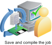
Compiling a Job
To compile a job, click the Compile button on the DataStage Designer toolbar. After compiling the job, the result appears in the display area. If the result of the compilation is Job successfully compiled with no errors, you can schedule or run the job. If an error is displayed, you can click the Show Error button to highlight the stage where the problem occurs. Ensure that you have specified all the input and output column definitions, directory paths, file names, and table names correctly.
Criteria Checked when Compiling JobsThe link to the source data stage is called the primary link. All other input links are called reference links.
During compilation, the following criteria in the job design are checked:
Primary Input: If you have more than one input link to a Transformer stage, the compiler checks that one is defined as the primary input link.
Reference Input: If you have reference inputs defined in a Transformer stage, the compiler checks that these are not from sequential files.
Key Expressions: If you have key fields specified in your column definitions, the compiler checks that there are key expressions joining the data tables.
Transforms: If you have specified a transform, the compiler checks that this is a suitable transform for the data element.
Specifying Job Run OptionsAfter compiling jobs, they become executable. The executable version of the job is stored in your project along with your job design.
To run a job, click the Run button on the DataStage Designer toolbar. After clicking the Run button the Job Run Options window appears, where you can specify information on running a server job.
In the Parameters tab, you enter specific parameter values for the job. You specify job parameters in the job properties window. You can create job-specific parameters or use an environment variable defined in DataStage Administrator. When running jobs, the parameters required to run the job are displayed in the Parameters tab of the Job Run Options window. If you specified default values in your job properties, these are displayed in the Parameters tab.
When setting values for environment variables, you can specify either $PROJDEF,, $ENV, or $UNSET special values:
When you use $ENV, DataStage uses the current setting for the environment variable.
When you use $PROJDEF, the current setting for the environment variable is retrieved and set in the job environment. This allows the environment variable value to be used anywhere in the job. If the value of that environment variable is subsequently changed in DataStage Administrator, the job picks up the new value without the need for recompiling.
When you use $UNSET, DataStage explicitly unsets the environment variable.
In the Limits tab, you specify any run time limits.
You can specify whether stages in the job should be limited in how many rows they process and whether runtime error warnings should be ignored.
You specify whether the job should generate operational metadata in the General tab.
You can also disable any message handlers specified for the job run in the General tab.
Editing Job Properties
The Job Properties window enables you to:
Editing Job Properties
To edit job properties, click the Job Properties button on the DataStage Designer toolbar.
The Job Properties window contains the following tabs:
|
Job Properties Page |
Description |
|
General |
Enter name, category description, version number, before and after job subroutines, and their input values. |
|
Parameters |
Define parameters to represent processing variables. Operators can be prompted for values at run time. |
|
Job Control |
Set up a job control routine using BASIC functions to call and run other jobs from the current job. You can also set up job control by using the Sequence Editor in the Designer module. |
|
Dependencies |
Enter any dependencies that this job has on functions, routines, or other jobs. |
|
Performance |
Displays options for improving performance. |
Using Expressions
Expressions define a value that is evaluated at run time.
Simple expressions can contain:
A string or numeric constant, for example, percent or 42.
A variable name.
A built-in or user-defined BASIC function.
A complex expression can contain a combination of constants, variables, operators, functions, and other expressions.
Accessing ExpressionsYou can access expressions by double-clicking a Transformer Stage within a job. Next you double-click the Derivation cell for any column in a transformer link and the Expression Editor opens. You can type an expression directly into the editor, or use the menu by clicking the Suggest button on the right side.
Different menus display depending on whether you right-click an input link, output link, the stage variable table, or links area background. The different menus are also dependent on what type of job you are working on (Server, Parallel, or Mainframe). The output link menu includes operations on Derivations. The input link menu includes operations on key expressions. The stage variable menu includes operations on stage variables.
To insert a function in your expression, click the Suggest button and select Function. The following choices are displayed:
Click the plus sign next to the function type to display the functions categorized under them.
Expression Editor OptionsThis table describes the menu options for the Expression Editor:
|
Expression Editor Menu Options |
Description |
|
DS Macro |
Insert a built-in DataStage BASIC Macro. |
|
DS Function |
Insert a built-in DataStage BASIC function. |
|
DS Constant |
Insert a predefined constant. |
|
DS Routine |
Insert a routine from the repository. |
|
DS Transform |
Insert a transform from the repository. |
|
Job Parameter |
Insert a parameter. |
|
Input Column |
Insert an input column name. |
|
Link Variables |
Insert a link variable |
|
Stage Variables |
Insert a stage variable. |
|
System Variables |
Insert a system variable. |
|
String |
Insert a string. |
|
Function |
Insert a function. |
|
() Parentheses |
Insert parentheses. |
|
If Then Else |
Insert If Then Else logic into the expression. |
Creating Constraints
Constraints, like expressions, enable you to filter or limit data based on criteria that you enter.
You can define a constraint or specify a reject link by both selecting an output link and clicking the Edit constraints button on the toolbar, or by double-clicking the output link header Constraint entry.
You can specify a constraint for each output link from a Transformer stage. You can also specify a particular link as a reject link. Reject links output rows that have not been written to any other output links from the Transformer stage.
In the example above, using the expression InsertFlag="Y" as a constraint verifies whether the lookup stages return a value. If no values were returned by the lookup stages, the InsertFlag field is set to N.
Using Hashed File Stages
Using hashed files improves job performance by enabling validation of incoming data rows without having to query a database each time a row is processed. These are called lookups. The hashed file can also be placed locally, eliminating time that would be spent accessing a remote server.
You can create hashed files to use as lookups in your jobs by running one of the delivered hash file jobs, or you can create a new job that creates a target hashed file. In many of the delivered PeopleSoft sequence jobs, the appropriate hashed file is refreshed as the last step following the load of the data table, which ensures synchronized updates to the data in the hashed file for use in future lookups.
Hashed file stages:
Represent hashed files, which use a specific algorithm for distributing records in one or more groups, typically to store data extracted from a database.
Can be used to extract or write data, or to act as an intermediate file in a job.
Are most commonly used as reference tables or lookups based on key fields.
Can have any number of inputs or outputs.
Can be static or dynamic.
Accessing Hashed File StagesTo access a hashed file stage, double-click the hashed file stage in a job.
The Hashed File Stage window contains the following tabs:
|
Window Element |
Usage |
|
Stage tab |
Define whether an account name or a directory path accesses the hashed file. |
|
Inputs or Output tab |
If the stage has an input, the Input tab is available. If it has an output, the Output tab is available. |
|
Inputs - General tab |
Enter the hashed file name. Select whether to create a new file, if none exists. Select whether to clear the file before writing to it. |
|
Inputs - Columns tab |
Select which columns of data will be written to the file. |
Creating Hashed File LookupsLookups are references that enable you to compare each incoming row of data to a list of valid values, and then accept or reject that row based on the validation result.
DataStage job stages can have two types of input links:
A Stream link represents where the data flow will flow, and is displayed as a solid line.
A Reference link represents a table lookup, and is displayed as a dotted line.
Stream links, represented by solid lines, can connect either active or passive stages. Reference links, shown as dotted lines, are only used by active stages. Their purpose is to provide information that may affect how the data is changed, but they do not supply the actual data to be changed.
Typically, hashed files are used as lookups because they are much quicker to access than querying a database. Hashed files used as lookups usually contain only one or two key columns against which incoming data can be validated.
Before you can create the lookup, you must first create a hashed file containing the values to be used as a reference. To add a lookup stage to a job, you select the hashed file stage from the File palette, enter the directory path and file name of the hashed file, and link the hashed file stage to a transformer stage.
You use a DRS stage as a lookup when your lookup requires that use of relational operators, such as >= and <=.
Using Job Sequencers
Job Sequencers enable you to:
Set up a sequence of server jobs to run.
Specify control information such as different course of action depending on load type or other criteria.
Designing job sequencers is similar to designing server jobs. You create the job sequence in DataStage Designer, add activities from the palette, and then join or sequence activities together using links. You control the flow of the activity sequence using triggers.
Once you have defined a job sequence, you can schedule and run the job from DataStage Director.
Note. Job sequencers can also be run using DataStage Director.
Using DataStage BASIC
If you need to load data from a non-PeopleSoft source, you usually do not have to perform any programming tasks: you can use the delivered transforms and routines, using the delivered jobs and sequences as templates. For more complex jobs, you can use DataStage BASIC to:
Define custom routines.
Define custom transforms.
Define derivation, expressions, and constraints in the transformer stage.
Define before-job or after-job subroutines.
Define job control routines.
PeopleSoft provides ETL jobs for loading data from PeopleSoft applications into EPM. Some of the PeopleSoft jobs use custom routines using DataStage BASIC.