3 SL150 SCSI Commands
Command Descriptor Block (CDB) Structure
-
The first byte contains the operation code — a Group Code that provides eight groups of commands and a Command Code that provides 32 command codes for each group.
-
The second byte starts the command parameters.
-
The last byte is the control byte (see "Control Byte Structure").
For some commands, a list of parameters accompanies the request during data out. For all commands, if there is an invalid parameter in the CDB, then the library terminates the command without altering the medium.


Control Byte Structure
The control byte is the last byte of every CDB.

Description of the illustration ''slk_068.png''
- Vendor Specific
-
Provides information about the device.
- NACA (Normal auto contingent allegiance)
-
Controls the rules for handling an auto contingent condition caused by a command. When NACA is 0, the command will return a check condition if a contingent allegiance condition occurs.
- Flag (not supported)
-
Causes an interrupt in the initiator allowing a device to respond with intermediate status. This bit is should be 0.
- Link (not supported)
-
Allows devices that support command linking to continue the I/O process. This bit should be 0.
Supported SCSI Command Status Byte Codes
- Good (00h)
-
Indicates the device successfully completed the command.
- Check Condition (02h)
-
Occurs when an error, unit exception, or abnormal condition generates sense data caused by one of the following conditions:
-
Issuing an invalid command or parameter
-
Issuing a command to a device that is not ready
-
Detecting a hardware error
-
Sensing an illegal request
-
- Busy (08h)
-
Occurs when the target cannot accept a command from an otherwise acceptable initiator. Normally, to recover from a Busy status, the initiator reissues the command.
- Reservation Conflict (18h)
-
Occurs whenever a SCSI initiator attempts to access a logical unit that is reserved by another initiator.
- Task Aborted (40h)
-
Occurs whenever the a task is aborted by another SCSI initiator port.
Initialize Element Status (07h)
Initialize Element Status (07h) requests an audit of the library. The library accepts this command for compatibility, but it does not perform any action.
At power-on the library performs a full audit and then maintains a cartridge inventory during operation. Use Read Element Status (B8h) to obtain the cartridge inventory.

Description of the illustration ''slk_069.png''
Initialize Element Status with Range (37h)
Initialize Element Status with Range (37h) requests an audit for a range of cells in the library. The library accepts this command for compatibility, but it does not perform any action.
At power-on the library performs a full audit and then maintains a cartridge inventory while operating. Use Read Element Status (B8h) to obtain the cartridge inventory.

Description of the illustration ''slk_070.png''
Inquiry (12h)
Inquiry (12h) requests information about library parameters.
Note:
The Inquiry command returns Check Condition (02h) status only when it cannot return the requested data. This command will not clear any pending unit attention conditions.
Description of the illustration ''slk_071.png''
- CmdDt (Command Support Data - not supported)
-
Set this to 0.
- EVPD (Enable vital product data)
-
0 = Requests standard inquiry data
1 = Requests vital support product data
- Page Code
-
If EVPD is 0, set the page code to 00h.
If EVPD is 1, set the page code to:
-
00h = Supported vital product page
-
80h = Unit serial number page
-
83h = Device identification page
-
88h = SCSI ports page
-
C8h = Vendor Specific Device Capabilities Page (Bridged HP LTO-6 Tape Drive)
-
- Allocation Length
-
The library transfers either the number of bytes specified by the Allocation Length field or all of the available inquiry data, whichever is less. The page lengths are:
-
0 = no inquiry data will be transferred. This is not considered an error.
-
24h = Standard Inquiry Data Length (IBM Bridged Tape Drive)
-
4Ah = Standard Inquiry Data Length (HP Bridged Tape Drive)
-
08h = Supported Pages Length
-
09h = Supported Pages Length (HP LTO-6 Bridged Tape Drive)
-
16h = Unit Serial Number Page Length
-
3Eh = Device Identification Page Length (IBM Bridged Tape Drive)
-
46h = Device Identification Page Length (HP Bridged Tape Drive)
-
34h = SCSI Ports Page Length
-
08h = Vendor Specific Device Capabilities Page Length (HP LTO-6 Bridged Tape Drive
-
Standard Inquiry Data Definition
Figure 3-4 Standard Inquiry Data Definition - HP Bridged

Description of ''Figure 3-4 Standard Inquiry Data Definition - HP Bridged''
Figure 3-5 Standard Inquiry Data Definition - IBM Bridged

Description of ''Figure 3-5 Standard Inquiry Data Definition - IBM Bridged''
- Peripheral Qualifier
-
000b = The specified peripheral device type is currently connected to this logical unit.
011b = The command was sent to an unsupported logical unit.
- Peripheral Device Type
-
08h = The library is a medium changer device.
1Fh = The command was sent to an unsupported logical unit.
- RMB (Removable Medium)
-
1 = The medium is removable.
- Version
-
05h = The library complies with SCSI-3.
- NACA (Normal Auto Contingent Allegiance - not supported)
-
0 = The library does not support setting NACA to one in the control byte of a CDB.
- HiSup (Hierarchical Addressing Support)
-
1 = The library uses the hierarchical addressing module to identify logical units.
- Response Data Format
-
2 = The data complies with the SCSI-3 specification.
- Additional Length
-
1Fh = The library has 31 additional bytes of Standard Inquiry Data available to the initiator.
45h = The library has 69 additional bytes of Standard Inquiry Data available to the initiator. This value is returned if the Allocation Length in the CDB is 36 bytes or larger.
- SCCS
-
0 = The library does not contain an embedded storage array controller component.
- ACC (Access Control Coordinator)
-
0 = The library does not contain an ACC that may be addressed through this logical unit.
- TPGS (Target Port Group Support)
-
01b = Implicit asymmetric logical unit access is supported. The SCSI target device is capable of changing target port asymmetric access states without a SET TARGET PORT GROUPS command. The REPORT TARGET PORT GROUPS command is supported and the SET TARGET PORT GROUPS command is not supported.
- 3PC (Third-Party Commands - not supported)
-
The library returns 0.
- Protect (Information Protection - not supported)
-
The library returns 0.
- VS (Vendor Specific)
-
0 = There is no vendor specific information with this command.
- MultiP
-
0 = There are no multiple target ports.
1 = The library has multiple target ports.
- MChngr
-
0 = The library is not embedded in or attached to a medium transport element.
- ADDR16
-
The library returns 0.
- WBUS16
-
The library returns 0.
- SYNC
-
The library returns 0.
- LINKED (Linked commands - not supported)
-
The library returns 0.
- CmdQue (Command Queuing)
-
0 = the library does not support command queuing
1 = the library supports command queuing
- SftRe (Soft Reset - not supported)
-
The library returns 0.
- Vendor Identification
-
Contains the ASCII character sequence ”STK” followed by blanks. If the specified logical unit is not supported, this field contains all blanks.
- Product Identification
-
Contains the ASCII character sequence ”SL150” followed by blanks.
- Product Revision Level
-
Contains an ASCII character sequence that represents the product revision level.
- Version Descriptors
-
The bridged drive returns up to eight Version Descriptors that are used to identify up to eight standards to which the drive conforms.
Supported Pages

Description of the illustration ''l207_271.png''
- Peripheral Qualifier
-
See Peripheral Qualifier.
- Peripheral Device Type
- Page Code
-
00h = The vital page
- Additional Page Length
-
4h = The library has 4 additional bytes of Supported Pages Inquiry data available to the initiator
5h = The bridged drive is an HP LTO-6 drive. The library has 5 additional bytes of Supported Pages Inquiry data available to the initiator
- Supported pages
-
80h = Unit serial number page
83h = Device identification page
88h = SCSI ports page
C8h = Vendor Specific Device Capabilities Page (Bridged HP LTO-6 Tape Drive)
Unit Serial Number Page

Description of the illustration ''slk_074.png''
- Peripheral Qualifier
-
See Peripheral Qualifier.
- Peripheral Device Type
- Page Code
-
80h = The unit serial number page.
- Additional Page Length
-
12h = 18 bytes of unit serial number data.
- Unit Serial Number
-
Contains a unique 18 character ASCII Serial Number for the library. For example:
-
464970G+1221XX0005
Where XX indicates the library partition identifier (such as P1 for partition 1). For nonpartitioned libraries, XX is 00.
-
Device Identification Page
Figure 3-6 Device Identification Page - HP Bridged

Description of ''Figure 3-6 Device Identification Page - HP Bridged''
Figure 3-7 Device Identification Page - IBM Bridged

Description of ''Figure 3-7 Device Identification Page - IBM Bridged''
- Peripheral Qualifier
-
See Peripheral Qualifier.
- Peripheral Device Type
- Additional Page Length
-
42h = 66d additional bytes of Device ID Inquiry Data available to the initiator.
- Protocol Identifier
-
0h = FC protocol
6h = Serial Attached SCSI
- Code Set
-
1h = Binary values
2h = ACSII printable characters
- Identifier Type
-
1h = Contains T10 Vendor ID data
3h = Contains a 64-bit IEEE formatted address
4h = Contains the Relative Target Port Identifier
- Identifier Length
-
04h = 4-bytes long for Relative Port Identifier
08h = 8-bytes long for Node Name Identifier
2Ah = Length for T10 Vendor ID data
- PIV (Protocol Identifier Valid)
-
0 = The protocol identifier contents are reserved
1 = The protocol identifier is valid
- Association
-
0 = The identifier field is associated with the addressed logical unit
1 = The identifier field is associated with the port that received the request
- NAA IEEE Registered Identifier
-
An 8-byte identifier. The first 4 bits are the Name Address Authority — NAA (5h). The next 24 bits are the Oracle company ID (00 10 4Fh). The remaining bits are the vendor-specific identifier. The NAA IEEE Registered Identifier is unique for each library and Fibre Channel port.
- Relative Target Port
-
01h = Port 1
02h = Port 2
- Vendor Identification
-
Contains the ASCII character sequence ”STK” followed by blanks. If the specified logical unit is not supported, this field contains all blanks.
- Product Identification
-
Contains the ASCII character sequence ”SL150” followed by blanks.
- Unit Serial Number
-
Contains a unique 18 character ASCII Serial Number for the library. For example:
-
464970G+1221XX0005
Where XX indicates the library partition identifier (such as P1 for partition 1). For nonpartitioned libraries, XX is 00.
-
SCSI Ports Page

Description of the illustration ''l207_274.png''
- Peripheral Qualifier
-
See Peripheral Qualifier.
- Peripheral Device Type
- Additional Page Length
-
18h = 24d additional bytes of SCSI Ports Data available to the initiator.
30h = 48d additional bytes of SCSI Ports Data available to the initiator. This value is returned, if the drive has 2 SCSI ports and both SCSI ports are enabled
SCSI Port Identification Descriptor Data

Description of the illustration ''l207_275.png''
- Relative Port Identifier
-
1 = Port 1
2 = Port 2
- Protocol Identifier
-
0 = Fibre Channel
6 = Serial Attached SCSI
- Code Set
-
1 = Binary values
- Association
-
1 = identifier field is associated with the port that received the request.
- PIV
-
1 = protocol identifier is valid
- Port Name Identification
-
Contains the 64-bit IEEE formatted address for the Port Name.
Specific Device Capabilities Page (HP LTO6 Bridged Tape Drive Only)

Description of the illustration ''l207_276.png''
- Peripheral Qualifier
-
See Peripheral Qualifier.
- Peripheral Device Type
- Page Code
-
C8h = Identifies the page as the vendor specific device capabilities page.
- Additional Page Length
-
14h = 4d bytes
Log Sense (4Dh)
Log Sense (4Dh) returns library error logs and statistics.

Description of the illustration ''slk_076.png''
- PPC (Parameter Pointer Control - not supported)
-
Set this to 0.
- SP (Save Parameters - not supported)
-
Set this to 0.
- PC (Page Control)
-
The library accepts values of 0 or 1.
- Page Code
-
00h = List supported pages
07h = List last n error events page
2Eh = Informational Exceptions TapeAlert page (0 or 1 in the PC field)
- Parameter Pointer
-
Set this to 0.
- Allocation Length
-
The library transfers either the number of bytes specified by the Allocation Length field or all of the available log sense data, whichever is less. The page lengths are:
-
00h = List Supported pages—length is 7h
-
07h = List Last n Error Events page—length is 3C4h
-
2Eh = Informational Exceptions TapeAlert page—length is 144h
-
Supported Pages Page
The Supported Pages Page lists all the Log Sense page codes supported by the library.

Description of the illustration ''l207_277.png''
Last n Errors Events Page
The Last n Errors Events page provides a list of the most recent errors events logged on the library. Each event is an ASCII string that includes a time stamp, a fault symptom code (FSC), and an optional mechanism. Each error event is 48 bytes long, and can contain up to 20 events. Time is in universal time.

Description of the illustration ''l207_278.png''
Informational Exceptions TapeAlert Page
The library provides the Informational Exceptions TapeAlert page at a minimum of:
-
At the beginning of a write/read job occurring on a device inside the library, even if media is not loaded in that device
-
Immediately after a fatal error during a write/read job occurring on a device inside the library
-
At the end of a write/read job occurring on a device inside the library
Though not mandatory, the host software may also poll the Log Sense page every 60 seconds while the tape library is idle. Each flag will be cleared to zero at library power on, when the TapeAlert Log page is read, or on a reset. The TapeAlert page returns A4h bytes in this format. The n represents a TapeAlert flag: currently, all values are set to default. Unsupported flags are also returned as defaults.

Description of the illustration ''l207_279.png''
- Parameter Code
-
2-byte filed that represents the TaptAlert flag number.
- DU (Disable Update)
-
0 = the target updates the log parameter instead of the initiator
- DS (Disable Save)
-
1 = saving the log is not supported
- TSD (Target Save Disable)
-
Always set to 0.
- ETC (Enable Threshold Comparison)
-
Always set to 0
- TMC (Threshold Met Criteria)
-
Always set to 0.
- LBIN (Not used)
-
Library returns 0.
- LP (List Parameter)
-
0 = log parameter is a data counter
- Parameter Length
-
Always set to 0x01. All are 1-byte flags.
- Flag
-
0x01 = the flag that the Parameter Code points to is active. All other values are off.
TapeAlert Flags
Flags are in sequential order, have valid values of 0 (off) or 1 (on), and reports all 32.
Type codes indicate C (critical), W (warning), and I (informational)
| Code | Flag Name | Type |
|---|---|---|
| 0001h | Media changer/data transfer device communication fault. Set when the operator removes a tape drive that has an assigned SCSI Element Address. If the library is partitioned, the tape alert is only set in the affected partition. | C |
| 0002h | Hardware Warning | W |
| 0003h | Mechanical Hardware Fault | C |
| 0004h | Hardware Fault | C |
| 0005h | Diagnostics Requested | I |
| 0006h | Host Interface Failure | C |
| 0007h | Predictive Failure | W |
| 0008h | Preventative Maintenance | W |
| 0009h | Humidity Limits | C |
| 000Ah | Temperature Limits | C |
| 000Bh | Voltage Limits | C |
| 000Ch | Unexpected Volume | W |
| 000Dh | Pick Retry | W |
| 000Eh | Place Retry | W |
| 000Fh | Load Retry | W |
| 0010h | Door Open | C |
| 0011h | Import/Export Element Fault | C |
| 0012h | Magazine Inaccessible | C |
| 0013h | Obsolete | |
| 0014h | Obsolete | |
| 0015h | Media Changer Offline | I |
| 0016h | Data Transfer Device Offline | I |
| 0017h | Barcode Scan Retry | W |
| 0018h | Inventory Information Inconsistent | C |
| 0019h | Media Changer Illegal Operation | W |
| 001Ah | Multi-port Interface Error on a Primary Port | W |
| 001Bh | Cooling Fan Failure | W |
| 001Ch | Power supply. Set when an operator either pulls a power supply or a power supply power cord. | W |
| 001Dh | Power Consumption | W |
| 001Eh | Pass-through Mechanism Failure | C |
| 001Fh | Obsolete | |
| 0020h | Unreadable Bar Code Labels | I |
Mode Select 6-byte (15h) and Mode Select 10-byte (55h)
The Mode Select commands specify operating parameters for the library. The library uses the configuration parameters during power-on or after a logical unit reset. If you set the parameter list length field to 0, then no Mode Select data is required. Otherwise, you must provide the following mode parameter data in a parameter list:
-
A 4-byte or 8-byte Mode Select Parameter Header
-
An 8-byte Fibre Channel Logical Unit Page or SAS Logical Unit Page
-
An 8-byte Fibre Channel Port Control Page or SAS Port Control Page
-
A 12-byte Information Exceptions TapeAlert Page
-
A 20-byte Element Address Assignment Mode Page
The library accepts the Mode Select command for compatibility, but the library does not support changing Mode parameters. The library returns a check condition if a SCSI host issues a Mode Select command and attempts to change a mode page. When the library receives a Mode Select command, the library validates all parameters. If a value is invalid, the library returns an error.


- PF (Page Format)
-
Set this to 1 to indicate the page format supports the SCSI-3 specification
- SP (Saved Pages)
-
0 = Current mode values are changed to the values specified by this command. Saved values are not affected.
1 = Current mode values and saved mode values are changed to the values specified by this command.
- Parameter List Length
-
The parameter list length field specifies the length in bytes of the mode parameter list that shall be contained in the data out sent by the host. The parameter list length is the sum of the length of the mode page header and one or more mode pages.
If the parameter length results in the truncation of the mode parameter header or mode page, then the command shall be terminated with CHECK CONDITION status, with the sense key set to ILLEGAL REQUEST, and the additional sense code set to PARAMETER LIST LENGTH ERROR.
A value of 00h is not considered an error.
For Mode Select 6:
HP Bridged Tape Drive Parameter List Lengths:
-
14h = Disconnect Reconnect Page
-
0Ch = Logical Unit Page
-
0Ch = Fibre Channel Port Control Page
-
14h = SAS Port Control Page
-
68h = SAS Phy Control and Discover Mode Subpage
-
10h = Informational Exceptions Tape Alert Mode Page
-
18h = Element Address Assignment Page
IBM Bridged Tape Drive Parameter List Lengths:
-
10h = Informational Exceptions Tape Alert Mode Page
-
18h = Element Address Assignment Page
For Mode Select 10:
HP Bridged Tape Drive Parameter List Lengths:
-
18h = Disconnect Reconnect Page
-
10h = Logical Unit Page
-
0C10h = Fibre Channel Port Control Page
-
18h = SAS Port Control Page
-
6Ch = SAS Phy Control and Discover Mode Subpage
-
140h = Informational Exceptions Tape Alert Mode Page
-
1Ch = Element Address Assignment Page
IBM Bridged Tape Drive Parameter List Lengths:
-
14h = Informational Exceptions Tape Alert Mode Page
-
1Ch = Element Address Assignment Page
-
Mode Select Parameter Header
The header definitions for the library must all be 00h.
Figure 3-10 Mode Select 6-Byte Parameter Header

Description of ''Figure 3-10 Mode Select 6-Byte Parameter Header''
Figure 3-11 Mode Select 10-Byte Parameter Header

Description of ''Figure 3-11 Mode Select 10-Byte Parameter Header''
FC Disconnect/Reconnect Page

Description of the illustration ''l207_280.png''
- PS (Parameters Saveable)
-
Set to 0.
- SPF (SubPage Format)
-
0 = the page_0 format is being used.
- Page Code
-
02h = Identifies the page as the Disconnect/Reconnect page
- Buffer Full Ratio
-
Indicates the device server, during read operations, how full the buffer should be prior to requesting an interconnect tenancy.
- Buffer Empty Ratio
-
Indicates the device server, during write operations, how empty the buffer should be prior to transmitting an FCP_XFER_RDY IU that requests the initiator to send data.
- Bus Inactivity Limit
-
Indicates the maximum time that the target is permitted to maintain an interconnect tenancy without data or information transfer, measured in transmission word increments.
0000h = no bus inactivity limit.
- Disconnect Time Limit
-
Indicates the minimum delay between interconnect tenancies measured in increments of 128 transmission words.
0000h = disconnect time limit does not apply.
- Connect Time Limit
-
Indicates the maximum duration of a single interconnect tenancy, measured in increments of 128 transmission words.
0000h = no connect time limit.
- Maximum Burst Size
-
Indicates the maximum size of FCP_DATA IU that the device server transfers to the initiator. This value is expressed in increments of 512 bytes.
0000h = no limit on the amount of data transferred per data transfer operation.
- EMPD (Enable Modify Data Pointers)
-
Indicates whether or not the target may use the random buffer access capability to reorder FCP_DATA IUs for a single SCSI command.
0 = Target shall generate continuously increasing relative offset values for each FCP_DATA IU for a single SCSI command.
1 = Target may transfer the FCP_DATA IUs for a single SCSI command in any order.
- FAA, FAB, FAC (Fairnes Access bits)
-
Indicate whether a target in a loop configuration shall use the access fairness algorithm. A value of 0 indicates that the target does not use fairness, while a value of 1 indicates that the target does use a fairness algorithm.
The FAA bit controls arbitration when the target wishes to send one or more FCP_DATA IU frames to an initiator.
The FAB bit controls arbitration when the initiator wishes to send one or more FCP_XFER_RDY IU frames to a target.
The FAC bit controls arbitration when the target wishes to send an FCP_RSP IU frame to an initiator.
- First Burst Size
-
0000h = no first burst size limit. This field value is expressed in increments of 512.
SAS Disconnect/Reconnect Page

Description of the illustration ''l207_281.png''
- PS (Parameters Saveable)
-
Set to 0.
- SPF (SubPage Format)
-
0 = the page_0 format is being used.
- Page Code
-
02h = Identifies the page as the Disconnect/Reconnect page
- Bus Inactivity Time Limit
-
This field contains the maximum time in 100 µs increments that an SSP target port is permitted to maintain a connection without transferring a frame to the SSP initiator port.
0000h = no bus inactivity limit.
- Maximum Connect Time Limit
-
This field contains the maximum duration of a connection in 100 µs increments.
0000h = no connect time limit.
- Maximum Burst Size
-
For read data, this field contains the maximum amount of data in 512-byte increments that is transferred during a connection by an SSP target port per I_T_L_Q nexus without transferring at least one frame for a different I_T_L_Q nexus.
For write data, the value shall specify the maximum amount of data that an SSP target port requests via a single XFER_RDY frame.
0000h in this field specifies that there is no maximum burst size.
- First Burst Size
-
If the ENABLE FIRST BURST bit in the COMMAND frame is set to zero, then the FIRST BURST SIZE field is ignored.
If the ENABLE FIRST BURST bit in the COMMAND frame is set to one, then the value in the FIRST BURST SIZE field contains the maximum amount of write data in 512-byte increments that may be sent by the SSP initiator port to the SSP target port without having to receive an XFER_RDY frame from the SSP target port.
Fibre Channel Logical Unit Page

Description of the illustration ''slk_081.png''
- PS (Parameters Savable)
-
The library sets this to 0.
- SPF (SubPage Format)
-
The library sets this to 0 to indicate page_0 format.
- Protocol Identifier
-
0h = FC protocol.
- EPDC (Enable Precise Delivery Checking)
-
0 = The target shall not use the precise delivery function and shall ignore the contents of the CRN field
1 = The logical unit shall use precise delivery function defined in the FCP-2 standard.
SAS Logical Unit Page

Description of the illustration ''l207_282.png''
- PS (Parameters Savable)
-
The library sets this to 0.
- SPF (SubPage Format)
-
The library sets this to 0 to indicate page_0 format.
- TLR (Transport Layer Retires)
-
0b = Disabled
1b = Enabled for Transfer Ready and Data Frames for the logical unit.
- Protocol Identifier
-
06h = Serial Attached SCSI protocol
Fibre Channel Port Control Page

Description of the illustration ''slk_082.png''
- PS (Parameters Savable)
-
The library sets this to 0.
- SPF (SubPage Format)
-
0 = page_0 format.
- Protocol Identifier
-
0h = FC protocol.
- DTFD (Disable Target Fabric Discovery)
-
If the library is not attached to an arbitrated loop, it will ignore the DTFD bit.
0 = The target attached by an arbitrated loop shall discover a fabric loop port if present on the loop and perform the public loop functions defined for targets by FC-FLA.
1 = The target attached by an arbitrated loop shall not recognize the presence of a fabric loop port on the loop.
- PLPB (Prevent Loop Port Bypass)
-
If the library is not attached to an arbitrated loop, it will ignore the PLPB bit.
0 = The target allows the Loop Port Bypass (LPB) and Loop Port Enable (PBE) primitive sequences to control the port bypass circuit and participation on the loop as specified by FC-AL-2.
1 = The target attached to an FC-AL-2 loop shall ignore any Loop Port Bypass (LPB) and Loop Port Enable (LPE) primitive sequences.
- DDIS (Disable Discovery)
-
If the library is not attached to an arbitrated loop, it will ignore the DDIS bit.
0 = The target shall wait to complete target discovery as defined by FC-PLDA, FC-FLA, and FC-TAPE before allowing processing of tasks to resume.
1 = The target without a valid FLOGI attached to an arbitrated loop will not require receipt of Address or Port Discovery (ADISC or PDISC ELSs) following loop initialization as described in FC-PLDA and FC-FLA.
- DLM (Disable Loop Master)
-
If the library is not attached to an arbitrated loop, it will ignore the DLM bit.
0 = The target may participate in loop master arbitration in the normal manner and, if successful, may become loop master during the loop initialization process.
1 = The target attached to an FC-AL-2 loop shall not participate in loop master arbitration and shall not become loop master. The target shall only repeat LISM frames it receives.
- RHA (Require Hard Address)
-
If the library is not attached to an arbitrated loop, it will ignore the RHA bit.
0 = The target follows the normal initialization procedure, including the possibility of obtaining a soft address during the loop initialization process.
1 = The target attached to an arbitrated loop shall only attempt to obtain its hard address. If there is a conflict for the hard address selection during loop initialization or the target does not have a valid hard address available, the target shall enter the nonparticipating state.
- ALWI (Allow Login without Loop Initialization)
-
If the library is not attached to an arbitrated loop, it will ignore the ALWI bit.
0 = The target shall perform the normal loop initialization procedure before entering the monitoring mode and accepting a login ELS.
1 = The target attached to an FC-AL-2 loop shall use the hard address available in the connector or in device address jumpers, enter the monitoring state in participating mode, and accept logins without using the loop initialization procedure (see FC-AL-2).
- DTIPE (Disable Target Initiated Port Enable)
-
If the library is not attached to an arbitrated loop, it will ignore the DTIPE bit.
0 = The target shall enable itself onto the loop in accordance to the rules specified in FC-AL-2.
1 = The target attached to an arbitrated loop shall wait for an initiator to send the Loop Port Enable (LPE) primitive sequence before inserting itself into a loop (see FC-AL-2)
- DTOLI (Disable Target Originated Loop Initialization)
-
If the library is not attached to an arbitrated loop, it will ignore the DTOLI bit.
0 = The target attached by an arbitrated loop shall generate LIP(F7,xx) after it enables a port into a loop.
1 = The target attached by an arbitrated loop shall not generate a LIP following insertion into the loop.
- RR_TOV Units (Resource Recovery Timeout Units)
-
011b = 0.1 second units.
- RR_TOV Values (Resource Recovery Timeout Value)
-
F0h = 24 seconds.
SAS Port Control Page

Description of the illustration ''l207_283.png''
- PS (Parameters Savable)
-
The library sets this to 0.
- SPF (SubPage Format)
-
0 = page_0 format.
- Page Code
-
19h = SAS Port Control mode page.
- Protocol Identifier
-
06h = Serial Attache SCSI protocol
- Cont. AWT (Continuous Arbitration Wait Time)
-
0 = The SAS port shall stop the AWT timer and set the AWT timer to zero when it receives an OPEN_REJECT (RETRY).
1 = The SAS port shall not stop the AWT timer and shall not set the AWT timer to zero when the SAS port receives an OPEN_REJECT (RETRY).
- BAE (Broadcast Asynchronous Event)
-
0 = Disable origination of Broadcast (Asynchronous Event).
1 = Enable origination of Broadcast (Asynchronous Event).
- Ready LED Meaning
-
The Ready LED Meaning bit specifies the READY LED signal behavior.
- I_T Nexus Loss Time
-
This field contains the minimum time that the SSP Target Port shall retry connection requests to an SSP initiator port that are rejected with responses indicating the SSP initiator port may no longer be present before recognizing an I_T nexus loss:
0000h = Vendor-specific amount of time.
0001h - FFFFh = Time in milliseconds.
FFFFh = The SSP target port shall never recognize an I_T nexus loss.
- Initiator Response Timeout
-
This field contains the minimum time in milliseconds that the SSP target port shall wait for the receipt of a frame before aborting the command associated with that frame.
0000h indicates that the SSP target port shall wait forever.
- Reject to Open Limit
-
This field contains the minimum time in 10 microsecond increments that the target port shall wait to establish a connection request with an initiator port on an I_T nexus after receiving an OPEN_REJECT (RETRY), OPEN_REJECT (RESERVED CONTINUE 0), or OPEN_REJECT (RESERVED CONTINUE 1).
0000h indicates that minimum time is vendor specific.
SAS Phy Control and Discover Mode Subpage

Description of the illustration ''l207_284.png''
- PS (Parameters Savable)
-
The library sets this to 0.
- SPF (SubPage Format)
-
0 = page_0 format.
- Page Code
-
19h = SAS Port Control mode page.
- SubPage Code
-
01h = SAS Phy Control and Discover Mode Subpage
- Protocol Identifier
-
06h = Serial Attache SCSI protocol
- Generation Code
-
This field is a one-byte counter that shall be incremented by one by the device server every time the values in this mode page are changed.
- Number of Phy
-
This field contains the number of phys in the SAS target device and indicates the number of SAS Phy Mode Descriptors in the SAS Phy Mode descriptor list.
SAS Phy Mode Descriptor Data

Description of the illustration ''l207_285.png''
- PS (Parameters Savable)
-
The library sets this to 0.
- Phy Identifier
-
A unique identifier is returned for each Phy.
- Attached Device Type
-
000b = No device attached
001b = SAS device
010b = Expander device
011b = Expander device compliant with a previous version of the SAS standard
- Negotiated Physical Link Rate
-
0h = UNKNOWN. Phy is enabled. Unknown Physical link rate.
1h = DISABLED. Phy is disabled.
2h = PHY_RESET_PROBLEM
3h = SPINUP_HOLD
4h = PORT_SELECTOR
8h = G1. Physical link rate is 1.5 Gb/s
9h = G2. Physical link rate is 3.0 Gb/s
Ah =G3. Physical link rate is 6.0 Gb/s
- Attached SSP, STP, SMP, SSP, STP, and SMP Initiator Port
-
This bit indicates the value of the Initiator Port field received in the IDENTIFY address frame during the identification sequence.
- SAS Address
-
The SAS Address of the drive that is the bridged interface for the library or partition.
- Attached SAS Address
-
The SAS Address field transmitted in the IDENTIFY address frame during the identification sequence.
- Attached Phy Address
-
The Attached Phy Address received in the IDENTIFY address frame during the identification sequence.
- Link Rate
-
8h = 1.5 Gb/s
9h = 3.0 Gb/s
Ah = 6.0 Gb/s
Information Exceptions TapeAlert Page

Description of the illustration ''l207_286.png''
- PS (Parameters Savable)
-
The library sets this to 0.
- SPF (SubPage Format)
-
0 = page_0 format.
- Perf
-
Performance bit is set to 0, which indicates acceptance of informational exception operations that cause delays.
- EBF
-
Enable Background Functions bit will always be 0.
- EWasc
-
This should be set to 0 for the enable warning bit, indicating warning reporting shall be disabled.
- DExcpt
-
The library accepts a value of 1, which indicates the target Disables All Information Exception operations and ignores the MRIE field. In this mode, the software must poll the TapeAlert Log page.
- Test
-
0 = The library does not generate false/test informational exceptions.
1 = The library generates false/test informational exception conditions.
- LogErr
-
The Log Error information exception conditions is set to 0, which indicates this is vendor-specific.
- MRIE
-
Method the library uses to Report Informational Exceptions must be 3h, which indicates that the library reports any informational exception conditions by returning Check Condition status.
- Interval Timer
-
Bytes 4 through 7 must be 00h. The library will only report informational exception condition one time.
- Report Counter/Test Flag Number
-
This is a dual purpose field:
When the Test Flag bit is 0, this field is the report counter. Bytes 8 through 11 must be set to 00h to indicate there is no limit to the number of times the library will report the informational exception condition. This value is returned with Mode Sense.
When the Test bit is 1, this field is the test flag number.
Test Modes
Two test mode options are supported in the current TapeAlert implementation.
Test Mode for All Bits Supported
Using the mode select command to initiate this test will set all of the flags supported by the TapeAlert implementation in the TapeAlert log page. The TapeAlert log sense page then can be read to give the host a snapshot of the supported flags.
The flags will be cleared when the page is read. To do this, set the test mode flag in the TapeAlert mode select page. This indicates that the Report Count/Test Flag Number field is in Test Flag Number mode. Next, set the test flag number to 0x7FFF and issue the Mode Select command. When the command is complete, the TapeAlert log sense page can be read.
Another test mode allows individual bits to be turned on. This can be useful for the host to debug/test operator interfaces.
Any flag set must be a supported flag. If the flag is not supported, a check condition with an incorrect parameter code is returned. The TapeAlert log sense page then can be read to allow the host to get a log page with the flag of interest set. The flag will be cleared when the page is read.
To test a flag, set the Test Flag in the TapeAlert mode select page. This indicates that the Report Count/Test Flag Number field is in Test Flag mode. Set the number of the flag to be tested. Issue the Mode Select command. When the command is complete, the TapeAlert log sense page can be read.
Element Address Assignment Mode Page
The library does not support changing Element Addresses. A check condition will be returned if the SCSI host issues a Mode Select command and attempts to change parameters in this page.
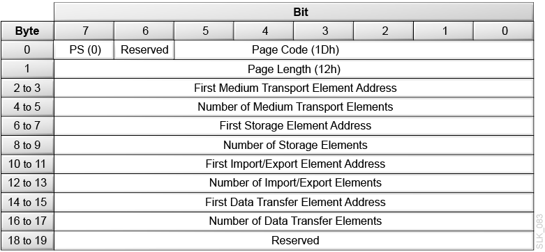
Description of the illustration ''slk_083.png''
- PS (Parameters Savable)
-
Set to 0.
- Page Code
-
1Dh = Element Address Assignment mode page.
- Parameter Length
-
12h = 18d bytes of parameter data following this byte
- First Medium Transport Element Address
-
0000h = The address of the robot in the library.
- Number of Medium Transport Elements
-
Identifies the number of hands in the library.
The library has only one hand, so this field must be 0001h (1d).
- First Storage Element Address
-
03E8h (1000d) = The address of the first data cartridge cell in the library or partition.
- Number of Storage Elements
-
The number of data cartridge cells in the library or partition. This number depends on the configuration of the library or partition. The number must be the same number returned by Mode Sense. To obtain this value, use Mode Sense of mode page 1Dh.
- First Import/Export Element Address
-
000Ah (10d) = The address of the first mailslot in the library or partition.
- Number of Import/Export Elements
-
The number of mailslots in the library or partition. This number depends on the configuration of the library or partition. The number must be the same number returned by Mode Sense. To obtain this value, use Mode Sense of mode page 1Dh.
- First Data Transfer Element Address
-
01F4h (500d) = The address of the first drive or empty drive slot in the library or partition. If the Address All Drive Slots option is set, then the first Data Transfer Element Address may be an empty drive slot.
- Number of Data Transfer Elements
-
The number of drives and empty drive slots in the library. This number depends on the configuration of the library. The number must be the same number returned by Mode Sense. To obtain this value, use Mode Sense of mode page 1Dh.
Element Address Assignments
An initiator can modify the element addresses in the library using a Mode Select command. The four element types are:
-
Medium transport (the hand)
-
Storage element (storage cells)
-
Import/export (mailslot cells)
-
Data transfer (tape drives)
Each element type is defined as a range of consecutive elements based on a starting element and a count. The ranges may be configured in any order, but one element type range may not overlap another element type range, and gaps between ranges are allowed.
To change the element address assignments, an initiator should first perform a Mode Sense of mode page 1Dh (Element Address Assignment Page). This provides the count of each element type. The count of each element type cannot be changed and must be used as obtained from the Mode Sense command. Only the starting element number can be modified. The initiator must calculate the starting addresses of each type to ensure no overlaps.
Because the library supports the saved page function, the element address assignments can be saved in non-volatile memory. These values are used to configure the library during power-on and after a logical unit reset.
Mode Sense 6-byte (1Ah) and Mode Sense 10-byte (5Ah)
The Mode Sense commands return information about the library's operating mode parameters. The data can be truncated to the length specified in the allocation length field. The library returns a Mode Sense Parameter Header followed by one or more of the following mode pages:


- LLBA (10-byte only)
-
Set this to 0. The library will return 0 for LONGBLA in the parameter data.
- DBD (Disable Block Descriptor)
-
The library ignores this field.
- Page Control
-
0h (00b) = Current Values. The library returns the requested pages with each supported parameter set to its current value.
1h (01b) = Changeable Parameter Values. The library returns the requested pages indicating which parameters the initiator can change (1 indicates a changeable parameters and 0 indicates an unchangeable parameter).
2h (10b) = Default Values. The library returns the requested pages with each supported parameter set to its default. The default values are the same as the current values. Parameters not supported by the library are set to 0.
3h (11b) = Saved Values. This option is valid only with mode pages that can be saved. If the mode page cannot be saved, then a Check Condition is returned
- Page Code
-
HP Bridged Tape Drive:
-
02h = Protocol Specific Disconnect/Reconnect page
-
18h = Protocol Specific Logical Unit page
-
19h = Protocol Specific Port Control page
-
1Ch = Informational Exceptions TapeAlert page
-
1Dh = Element Address Assignment page
-
1Eh = Transport Geometry page
-
1Fh = Device Capabilities page
-
3Fh = All pages (in the above order)
IBM Bridged Tape Drive:
-
1Ch = Informational Exceptions TapeAlert page
-
1Dh = Element Address Assignment page
-
1Eh = Transport Geometry page
-
1Fh = Device Capabilities page
-
3Fh = All pages (in the above order)
-
- SubPage Code
-
Specifies which mode subpages are returned by the library. The supported mode subpages depend on the bridged tape drive.
HP Bridged Tape Drive: The field indicates the Serial Attached SCSI Port Control subpage, when the protocol is Serial Attached SCSI and the Page Code is set to 19h. The following subpages are supported:
01h = Serial Attached SCSI Phy Control and Discover Mode Subpage
02h = Serial Attached SCSI Shared Port Control Mode Subpage
03h = Serial Attached SCSI Enhanced Phy Control Mode Subpage
IBM Bridged Tape Drive: This field must be 00h. There are no supported mode subpages.
- Allocation Length
-
The allocation length field specifies the maximum number of bytes that the initiator has allocated for data returned from the Mode Sense command. The library transfers either the number of bytes specified by the allocation length field or all of the available mode sense data, whichever is less. The allocation length depends on the mode page and the bridged tape drive. The maximum number of bytes returned by the library is 68h (104d) bytes for Mode Sense 6 and 6Ch (108h) bytes for Mode Sense 10.
A value of 00h indicated that no mode sense data is to be transferred. This condition is not considered an error.
For Mode Sense 6-byte:
HP Bridged Tape Drive:
-
04h = Mode Sense 6 Parameter Header Length
-
08h = Mode Sense 10 Parameter Header Length
-
10h = Disconnect Reconnect Page Length
-
08h = Logical Unit Page Length
-
08h = Fibre Channel Port Control Page Length
-
10h = SAS Port Control Page Length
-
64h = SAS Phy Control and Discover Mode Subpage Length
-
0Ch = Informational Exceptions Tape Alert Mode Page Length
-
14h = Element Address Assignment Page Length
-
04h = Transport Geometry Page Length
-
14h = Device Capabilities Page Length
IBM Bridged Tape Drive:
-
04h = Mode Sense 6 Parameter Header Length
-
08h = Mode Sense 10 Parameter Header Length
-
0Ch = Informational Exceptions Tape Alert Mode Page Length
-
14h = Element Address Assignment Page Length
-
04h = Transport Geometry Page Length
-
14h = Device Capabilities Page Length
IBM Bridged Tape Drive:
-
08h = Mode Sense Parameter Header Length
-
0Ch = Informational Exceptions Tape Alert Mode Page Length
-
14h = Element Address Assignment Page Length
-
04h = Transport Geometry Page Length
-
14h = Device Capabilities Page Length
-
Mode Sense Parameter Header
Figure 3-14 Mode Sense 6-Byte Parameter Header

Description of ''Figure 3-14 Mode Sense 6-Byte Parameter Header''
Figure 3-15 Mode Sense 10-Byte Parameter Header

Description of ''Figure 3-15 Mode Sense 10-Byte Parameter Header''
- Mode Data Length
-
The bytes of parameter information available regardless of the allocation length. This value excludes the Mode Data Length byte, but includes three additional bytes (for Mode Sense 6-byte) or six additional bytes (for Mode Sense 10-byte) and the length of any mode pages that follow.
- Block Descriptor Length (not supported)
-
The library returns 0.
SAS Shared Control Mode Subpage

Description of the illustration ''l207_287.png''
- PS (Parameters Saveable)
-
The library returns 0.
- SPF (SubPage Format)
-
The library returns a value of 1 for the SubPage Format bit, indicating this page uses the sub_page mode page format.
- Page Code
-
The value 19h identifies the page as the SAS Port Control mode page.
- Subpage Code
-
The value 02h identifies the sub-page as the SAS Shared Port Control Mode Subpage.
- Protocol Identifier
-
06h = Serial Attache SCSI protocol.
- Power Loss Timeout
-
This field contains the maximum time, in one millisecond increments, that a target port shall respond to connection requests with OPEN_REJECT (RETRY) after receiving NOTIFY (POWER LOSSEXPECTED).
The value 0000h indicates that maximum time is vendor-specific.
SAS Enhanced Phy Control Subpage

Description of the illustration ''l207_288.png''
- PS (Parameters Saveable)
-
The library returns 0.
- SPF (SubPage Format)
-
The library returns a value of 1 for the SubPage Format bit, indicating this page uses the sub_page mode page format.
- Page Code
-
The value 19h identifies the page as the SAS Port Control mode page.
- Subpage Code
-
03h = SAS Enhanced Phy Control Mode Subpage
- Protocol Identifier
-
06h = Serial Attache SCSI protocol.
- Generation Code
-
This field is a one-byte counter that shall be incremented by one by the device server every time the values in this mode page are changed.
- Number of Phys
-
This field contains the number of phys in the SAS target device and indicates the number of Enhanced Phy Control Mode Descriptors in the Enhanced Phy Control Mode descriptor list.
Enhanced Phy Control Mode Descriptor Data

Description of the illustration ''l207_289.png''
- Phy Identifier
-
A unique Phy Identifier is returned for each Phy.
- Descriptor Length
-
The library returns a value of 10h (16d) bytes.
- Programmed, Current, and Attached Phy Capabilities
-
This field indicates the SNW-3 (Speed Negotiation Window) Phy capabilities bits that are going to be transmitted in the next link reset sequence containing SNW-3 as defined below. If the last link reset sequence did not include SNW-3, then the field will be set to 00000000h.
- Negotiated SSC
-
The Negotiated SSC bit is only valid when the Negotiated Physical Link Rate is great than or equal to 8h. When valid:
0 = SSC is enabled.
1 = SSC is disabled.
- Hardware Muxing Support
-
0 = The Phy does not support multiplexing.
1 = The Phy supports multiplexing.
Phy Capabilities Data

Description of the illustration ''l207_290.png''
- TX SSC Type
-
The value 0 indicates that the phy's transmitter uses down-spreading SSC when SSC is enabled (for example, the phy is a SAS phy), or that the phy does not support SSC.
The value 1 indicates that the phy's transmitter uses center-spreading SSC when SSC is enabled (for example, the phy is an expander phy).
- Requested Logical Link Rate
-
This field indicates if the Phy device supports multiplexing and, if so, the logical link rate that the Phy device is requesting.
- G* With and Without SSC
-
0 = Does not support
1 = Supports that G level
- Parity
-
The Parity bit shall be set to one or zero such that the total number of SNW-3 Phy device capabilities bits that are set to one is even, including the Start bit and the Parity bit.
Transport Geometry Mode Page

Description of the illustration ''slk_091.png''
- PS (Parameters Savable)
-
The library returns 0.
- Page Code
-
1Eh = the Transport Geometry mode page.
- Page Length
-
The number of additional types of transport geometry descriptor data to follow the header. Each descriptor has two bytes of information.
02h = The library has one transport mechanism.
- Rotate
-
0 = The library does not use multiple-sided media.
- Member Number in Transport Element Set
-
Identifies the transport element in the system.
00h = The library has one transport element.
Device Capabilities Page
-
DT — Data Transfer Element (drive)
-
I/E — Import/Export Element (CAP cells)
-
ST — Storage Element (cartridge storage cell)
-
MT — Medium transport (robot hand)

Description of the illustration ''slk_092.png''
- PS (Parameters Savable)
-
The library returns 0.
- Page Code
-
1Fh = The Device Capabilities mode page.
- Page Length
-
12h = 18 bytes of device capabilities data to follow.
- StorDT
-
1 = A tape drive can function as element storage.
- StorI/E
-
1 = A CAP cell can function as element storage.
- StorST
-
1 = A cartridge cell can function as element storage.
- StorMT
-
0 = The robot hand cannot function as element storage. You cannot use the robot as the source or destination of a move.
- MT > DT, MT > I/E, MT > ST, MT > MT, ST > MT, I/E > MT, DT > MT
-
0 = The robot hand (MT) cannot be the source or destination of a move.
- ST > DT, ST > I/E, ST > ST, I/E > DT, I/E > I/E, I/E > ST, DT > DT, DT > I/E, DT > ST
-
1 = Tape drives (DT), CAP cells (I/E), and cartridge cells (ST) are valid sources or destinations for a move.
- All <> Parameters
-
0 = The library does not support the exchange medium command.
Move Medium (A5h)
Move Medium (A5h) moves a cartridge tape from one element location to another. Device Capabilities Page of the Mode Sense command provides a matrix with the valid source and destination element combinations for Move Medium.
The Fast Load option on the library controls the completion of the move command when the destination element is a tape drive. If the fast load option is disabled, the library performs the move motion and waits until the tape drive load operation completes before returning status for the move command. When the fast load option is enabled, the library performs the move motion and verifies the tape drive load starts before returning status for the move command.
Note:
If you issue a Move command from a CAP cell that contains an upside down cartridge, the library will return a check condition and set the sense data to Illegal Request (05h), ASC to 3Bh, and ASCQ to 18h.
Description of the illustration ''slk_093.png''
- Transport Element Address
-
00h = The default robot hand. All other values will be ignored.
- Source Element Address
-
The element address for the cartridge, which can be a storage cell, a CAP slot, or a tape drive.
- Destination Element Address
-
The element address for the cartridge move, which can be a storage cell, a CAP cell, or a tape drive.
- Invert (not supported)
-
Set this to 0.
- Move Option
-
00b = The library performs a normal move operation
01b = Not supported
10b = The library performs a mount operation with write protection enabled. This is only valid if the destination is a drive. If the drive does not support this feature or fails to acknowledge the write-protected mount option, the mount fails and the library returns the Hardware Error sense key (04) with an ASC of 40 and an ASCQ of 02 (Drive Error).
11b = The drive performs a rewind, unload, and then move operation. This option is valid only when the source element address is a drive.
Caution:
The 11b option might interfere with operations on the drive data path.
Persistent Reserve In (5Eh)
Persistent Reserve In (5Eh) returns information about active registrations or an active reservation. You can use Persistent Reserve In to help resolve contention among multiple initiators and multiple-port targets within the system.

Description of the illustration ''slk_094.png''
- Service Action
-
00h = Returns Read Keys Data
01h = Returns Read Reservation Data
02h = Returns Report Capabilities Data
03h = Returns Read Full Status Data
04h through 1Fh are reserved.
- Allocation Length
-
Indicates the space reserved for the returned parameter list. If the length is not sufficient to contain the entire parameter list, the parameter list will be incomplete. However, a partial list is not an error
Read Keys Data
The Read Keys Data is a list of all the currently registered reservation keys.

Description of the illustration ''slk_095.png''
- PR Generation
-
A 32-bit counter that increments each time a Persistent Reserve Out command requests a Register, a Register and Ignore, a Clear, a Preempt, or a Preempt and Abort operation. The counter allows the application client to determine if another application client has changed the configuration.
A Power-On-Reset sets the counter to zero.
- Additional Length
-
The number of bytes in the reservation key list.
- Reservation Key List
-
Contains the eight-byte reservation keys registered with the library through a Persistent Reserve Out command.
Read Reservation Data
The Read Reservation Data is a description of all currently registered reservation keys.

Description of the illustration ''slk_096.png''
- PR Generation
-
A 32-bit counter that increments each time a Persistent Reserve Out command requests a Register, a Register and Ignore, a Clear, a Preempt, or a Preempt and Abort operation. The counter allows the application client to determine if another application client has changed the configuration.
A Power-On-Reset sets the counter to zero.
- Additional Length
-
The number of bytes in the reservation descriptor list.
0 = No reservation held
16 = Active reservation data
Reservation Descriptor
Each persistent reservation for a logical unit has one reservation descriptor that has the format shown below.

Description of the illustration ''slk_097.png''
- Reservation Key
-
The reservation key for the descriptor data that follows.
- Scope
-
Indicates whether a persistent reservation applies to an entire logical unit or to an element. The only valid value is 0h.
0h = The persistent reservation applies to the logical unit
- Type
-
3h = Exclusive access. The initiator holding the persistent reservation has exclusive access. Some commands (such as Move Medium) are only allowed for the persistent reservation holder.
6h = Exclusive Access, Registrants Only. Any currently registered initiator has exclusive access. Some commands (such as Move Medium) are only allowed for registered I_T nexuses.
8h = Exclusive Access, Registrants Only: This value indicates that any currently registered initiator has exclusive access. Some commands (such as Move Medium) are only allowed for registered I_T nexuses.
Report Capabilities Data

Description of the illustration ''slk_098.png''
- Length
-
The length in bytes of the parameter data.
- CRH (Compatibility Reservation Handling)
-
1 = The library supports the exceptions to the SPC-2 RESERVE and RELEASE commands as described in SPC-3.
- SIP_C (Specify Initiator Ports Capable)
-
1 = The library supports the SPEC_I_PT bit in the PERSISTENT RESERVE OUT command parameter data.
- ATP_C (All Target Ports Capable)
-
0 = The library does not support the ALL_TG_PT bit in the Persistent Reserve Out (5Fh) command parameter data.
1 = The library supports the ALL_TG_PT bit in the PERSISTENT RESERVE OUT command parameter data.
- PTPL_C (Persist Through Power Loss Capable)
-
0 = The library does not support the persist through power loss capability for persistent reservations and the APTPL bit in the Persistent Reserve Out (5Fh) command parameter data.
1 = The library supports the persist through power loss capability for persistent reservations and the APTPL bit in the in PERSISTENT RESERVE OUT command parameter data
- TMV (Type Mask Valid)
-
0 = Ignore the persistent reservation type mask.
1 = The persistent reservation type mask field contains a bit map indicating which persistent reservation types the library supports.
- PTPL_A (Persist Through Power Loss Activated)
-
0 = The library does not support the Persist Through Power Loss Activated bit.
1 = The persist through power loss capability is activated.
- WR_EX_AR (Write Exclusive-All Registrants)
-
0 = The library does not support the Write Exclusive-All Registrants persistent reservation type.
- EX_AC_RO (Exclusive Access Registrants Only)
-
1 = The library supports this persistent reservation type.
- WR_EX_RO (Write Exclusive Registrants Only)
-
0 = The library does not support the Write Exclusive-Registrants Only persistent reservation type.
- EX_AC (Exclusive Access)
-
1 = The library supports this persistent reservation type.
- WR_EX (Write Exclusive)
-
0 = The library does not support the Write Exclusive persistent reservation type.
- EX_AC_AR (Exclusive Access All Registrants)
-
0 = The library does not support the Exclusive Access-All Registrants persistent reservation type.
Read Full Status Data
The Read Full Status service action requests that the library return a list of all the current Reservation keys it has registered along with information about each initiator.

Description of the illustration ''l207_291.png''
- PR Generation
-
A 32-bit counter that increments each time a Persistent Reserve Out command requests a Register, a Register and Ignore, a Clear, a Preempt, or a Preempt and Abort operation. The counter allows the application client to determine if another application client has changed the configuration.
A Power-On-Reset sets the counter to zero.
- Additional Length
-
Number of bytes in the list of the full status descriptors.
Full Status Descriptor

Description of the illustration ''l207_292.png''
- Reservation Key
-
The reservation key for the descriptor data that follows.
- ALL_TG_PT (All Target Port Groups)
-
0 = single I_T nexus.
1 = all the I_T nexuses that are associated with both the initiator port specified by the Transport ID Data and every target port in the SCSI target device. Indicates that all the I_T nexuses are registered with the same reservation key and all the I_T nexuses are either reservation holders or not reservation holders as indicated by the R_HOLDER bit.
- R_Holder
-
0 = All I_T nexuses described by this full status descriptor are registered but are not persistent reservation holders.
1 = All I_T nexuses described by this full status descriptor are registered and are persistent reservation holders.
- Type
-
When the Reservation Holder Bit is 1, this field indicates the type of Persistent Reservation:
3h = Exclusive Access
6h = Exclusive Access - Registrants Only
8h = Exclusive Access - All Registrants
- Relative Target Port Identifier
-
1 = Target Port 1
2 = Target Port 2
Persistent Reserve Out (5Fh)
Persistent Reserve Out (5Fh) uses service actions to create, manage, or remove a persistent reservation.
The application client provides a registered reservation key that identifies the initiator. An application client may use the Persistent Reserve In (5Eh) command to obtain the reservation key for the initiator holding a persistent reservation. The client may use the Persistent Reserve Out command to preempt that persistent reservation.
Note:
For more information on command processing when the library has a persistent reservation, see "Reservation Handling".
Description of the illustration ''slk_125.png''
- Service Action
-
00h = Register — registers or unregisters a reservation key.
01h = Reserve — creates a persistent reservation of the scope and type specified in Byte 2.
02h = Release — removes an active persistent reservation, if the initiator holds the persistent reservation.
03h = Clear — clears all persistent reservations for all initiators and reset all reservation keys to 0.
04h = Preempt — removes all reservations and registrations for the initiators associated with the service action reservation key in the parameter list.
05h = Preempt and Abort — perform a Preempt action and terminate all commands by initiators associated with the cleared service action reservation key. This also clears any CAP locks and contingent allegiance in effect for these initiators.
06h = Register and Ignore Existing Key — registers or unregisters a reservation key with the library.
07h = Register and Move — register a reservation key for another I_T nexus with the device server and move a persistent reservation to that I_T nexus.
- Scope
-
Indicates whether a persistent reservation applies to an entire logical unit or to an element.
0h = The persistent reservation applies to the logical unit (library or partition). This is the only valid value.
- Type
-
3h = Exclusive access. The initiator holding the persistent reservation has exclusive access. Some commands (such as Move Medium) are only allowed for the persistent reservation holder.
6h = Exclusive Access, Registrants Only. Any currently registered initiator has exclusive access. Some commands (such as Move Medium) are only allowed for registered initiators.
8h = Exclusive Access, All Registrants: Some commands (for example, Move Medium) are only allowed for registered I_T nexuses. Each registered I_T nexus is a persistent reservation holder.
- Parameter List Length
-
The parameter data for the Persistent Reserve Out command includes all fields, even when a field is not required for the specified service action.
Persistent Reserve Out Parameter List

Description of the illustration ''slk_126.png''
- Reservation Key
-
An 8-byte value that identifies the initiator.
- Service Action Reservation Key
-
This field contains information needed for five service actions: Register, Register and Ignore Existing Key, Preempt, Preempt and Abort, and Register and Move.
- SPEC_I_PT (Specify Initiator Ports - not supported)
-
The Specify Initiator Ports bit is only applicable to the Register and Register and Ignore Service Actions:
0 = The library shall apply the registration only to the I_T nexus that sent the Persistent Reservation Out command.
1 = The additional parameter data shall include a list of Transport IDs and the library shall also apply the registration to the I_T nexus for each initiator port specified by a TransportID.
- ALL_TG_PT (All Target Ports - not supported)
-
The All Target Ports bit is not supported and must be set to 0.
- APTPL (Activate Persist Through Power Loss)
-
The Activate Persist Through Power Loss bit is only valid for the Register, Register and Ignore, and Register and Move service actions and is defined as follows:
0 = The library shall not preserve any persistent reservation and all registrations if power is lost and later returned.
1 = The library preserves any persistent reservation and all registrations if power is lost and later returned.
Table 3-1 Persistent Reserve Out Service Actions and Valid Parameters
| Service Action | Scope | Type | Reservation Key | Service Action Res. Key | ALL_TG_PT, and APTPL | SPEC_I_PT |
|---|---|---|---|---|---|---|
|
Register |
Ignored |
Ignored |
Valid |
Valid |
Valid |
Valid |
|
Register and Ignore |
Ignored |
Ignored |
Ignored |
Valid |
Valid |
Valid |
|
Reserve |
LU_SCOPE |
Valid |
Valid |
Ignored |
Ignored |
Ignored |
|
Release |
LU_SCOPE |
Valid |
Valid |
Ignored |
Ignored |
Ignored |
|
Clear |
Ignored |
Ignored |
Validy |
Ignored |
Ignored |
Ignored |
|
Preempt |
LU_SCOPE |
Valid |
Valid |
Valid |
Ignored |
Ignored |
|
Preempt Abort |
LU_SCOPE |
Valid |
Valid |
Valid |
Ignored |
Ignored. |
|
Register and Move |
LU_SCOPE |
Valid |
Valid |
Valid |
Valid |
Ignored |
Table 3-2 Service Action Reservation Key Information
| If the service action is... | Then the information in the field is the... |
|---|---|
|
Register |
New reservation key to be registered. |
|
Register and Ignore Existing Key |
New reservation key to be registered. |
|
Preempt |
Reservation key of the persistent reservation being preempted. |
|
Preempt and Abort |
Reservation key of the persistent reservation being preempted. |
|
Register and Move |
Reservation key to be registered on the specified I_T nexus. |
Position to Element (2Bh)
Position to Element (2Bh) moves the robot to the destination element.
Note:
The Position to Element command (2Bh) is supported only for compatibility with existing applications. The library accepts this command for compatibility.
Description of the illustration ''slk_099.png''
- Transport Element Address
-
0000h = The element address of the robot.
- Destination Element Address
-
The element address of the storage cell, mailslot cell, or drive. The robot positions the hand at this location.
- Invert (not supported)
-
Set this to 0.
Prevent/Allow Medium Removal (1Eh)
The Prevent/Allow Medium Removal command (1Eh) requests that the library enable or disable operator access to the mailslot and magazine(s).
-
If allowed, the mailslot and magazine(s) are unlocked. The mailslot may be opened and the magazine(s) may be unlatched from the user interface.
-
If prevented, the mailslot and magazine(s) are locked. The mailslot cannot be opened and the magazine(s) cannot be unlatched from the user interface.
All initiators are set to an allow media removal state, which enables user interface access to the mailslots and magazine(s), after a power on reset, library reset, bridged tape drive reset, or SCSI task management reset that affects LUN 1.
The Prevent/Allow Media Removal Behavior depends on the bridged tape drive in a multi-initiator environment.
-
The HP Bridged Tape Drive keeps Prevent/Allow data on a per-initiator basis. If any initiator has set a prevent state, the library prevents anyone from open8ing the mailslot or unlatching the magazine(s).
-
The IBM Bridged Tape Drive keeps Prevent data on a per-initiator basis. If any initiator issues an Allow Media Removal command, then the Prevent data is cleared for all initiators and Media Removal is allowed.

Description of the illustration ''slk_100.png''
- Prevent
-
0 = Allow — The library unlocks the mailslot and magazines.
1 = Prevent — The library locks the mailslot and magazines.
Read Element Status (B8h)
Read Element Status (B8h) returns the status of elements in the library or partition.
The library returns an eight-byte Element Status Data Header, followed by an element page (or four element pages if you set the type code to All Element Types). Each element page consists of an eight-byte Element Status Page Header, followed by the element type descriptor. Supported element type descriptors include:

Description of the illustration ''slk_101.png''
- VolTag
-
0 = The library does not report Volume Tag information
1 = The library reports Volume Tag information
- Element Type Code
-
0h = All Element Types
1h = Medium Transport Element (robot hand)
2h = Storage Element (cartridge cells)
3h = Import/Export Element (mailslot cells)
4h = Data Transfer Element (drives or empty drive slots)
- Starting Element Address
-
Specifies the minimum element address. The library reports elements with an element address greater than or equal to the Starting Element Address.
- Number of Elements
-
The maximum number of element descriptors to transfer. This is not an element address range.
- CurData
-
The library ignores the CurData bit and will use the robots to obtain information if needed.
0 = The library can use the robots to gather data
1 = The library will not perform mechanical operations to obtain the data
- DvcID
-
0 = The library will not return device identification information
1 = The library returns device identification information for data transfer elements.
- Allocation Length
-
The length in bytes of the space allocated by the initiator for the transfer of element descriptors. Only complete element descriptors are transferred. Data can be truncated based on the length specified in the allocation field.
Element Status Data Header

Description of the illustration ''slk_102.png''
- First Element Address Reported
-
The lowest element address found for the specified Element Type Code that is greater than or equal to the Starting Element Address.
- Number of Elements Available
-
The number of elements found for the specified Element Type Code that are greater than or equal to the Starting Element Address. This number is always less than or equal the Number of Elements specified in the CBD.
- Byte Count of Report Available
-
The number of bytes of element status data available. This count does not include the Element Status Data header bytes. The count is not adjusted to match the allocation length you specified in the Read Element Status command.
Element Status Page Header

Description of the illustration ''slk_103.png''
- Element Type Code
-
1h = Medium Transport Element (robot hand)
2h = Storage Element (cartridge cells)
3h = Import/Export Element (mailslot cells)
4h = Data Transfer Element (drives or empty drive slots)
- PVolTag
-
0 = The library omits Primary Volume Tag information from the element descriptors.
1 = The library includes Primary Volume Tag information in the element descriptors.
- AVolTag
-
0 = The library does not support Alternative Volume Tags.
- Element Descriptor Length
-
The total number of bytes contained in a single element descriptor.
- Byte Count of Descriptor Data Available
-
The number of bytes of element descriptor data available. This count does not include the Element Status Page header bytes. The count is not adjusted to match the allocation length you specified in the Read Element Status command.
- Element Descriptors
-
Medium Transport Element Descriptor
Import/Export Element Descriptor
Element Descriptors
Figure 3-16 Medium Transport Element Descriptor

Description of ''Figure 3-16 Medium Transport Element Descriptor''

Figure 3-18 Import/Export Element Descriptor

Description of ''Figure 3-18 Import/Export Element Descriptor''
Figure 3-19 Data Transfer Element Descriptor (DvcID = 0)

Description of ''Figure 3-19 Data Transfer Element Descriptor (DvcID = 0)''
Figure 3-20 Data Transfer Element Descriptor (DvcID = 1)

Description of ''Figure 3-20 Data Transfer Element Descriptor (DvcID = 1)''
- Element Address
-
The address of the element (robot hand, cartridge cell, CAP cell, drive, or empty drive slot).
- OIR
-
0 = No operator intervention required to make the CAP accessible
1 = Operator intervention required to make the CAP accessible
- CMC
-
0 = The import/export element is a CAP. The cartridge will not leave the library when prevented by the Prevent/Allow Medium Removal (1Eh) command.
- InEnab
-
1 = The CAP supports importing cartridges.
- ExEnab
-
1 = The CAP supports exporting cartridges.
- Access
-
0 = The robot cannot access the element. For Import/Export elements, this can occur when the CAP is open or a CAP magazine was removed. For Data transfer elements, this can occur when a cartridge is loaded in a drive.
1 = The robot can access the element
- Except
-
0 = The element is in a normal state
1 = The element is in an abnormal state. The Additional Sense Code (ASC) and the Additional Sense Code Qualifier (ASCQ) fields contain information regarding the abnormal state. Other fields in the descriptor might be invalid and should be ignored.
- ImpExp
-
0 = The robot placed the cartridge in the CAP for an export operation.
1 = An operator placed the cartridge in the CAP for an import operation.
- Full
-
0 = The element does not contain a cartridge
1 = The element contains a cartridge
- ASC (Additional Sense Code)
-
This field is valid only if the Except bit is set. In the case of an exception, it contains an ASC as defined for Request Sense data.
- ASCQ (Additional Sense Code Qualifier)
-
This field is valid only if the Except bit is set. In the case of an exception, it contains an ASCQ as defined for Request Sense data.
Condition ASC Value ASCQ Value CAP Open 3Ah 02h Empty Drive Slot (no drive installed) 3Bh 1Ah Drive Hardware Error 40h 02h - SValid
-
0 = The Source Element Address and Invert fields are not valid.
1 = The Source Element Address and Invert fields are valid.
- Invert (not supported)
-
0 = The library does not support multi-sided media.
- ED
-
0 = The element is enabled.
1 = The element is disabled (for example an open CAP, a drive hardware error, or empty drive slot).
- Medium Type
-
The type of medium currently present in the element as determined by the medium changer.
0h = Unspecified - the medium changer cannot determine the medium type.
1h = Data Medium
2h = Cleaning Medium
- Source Storage Element Address
-
This field is valid only if the SValid field is 1. This field provides the address of the last storage element this cartridge occupied. The element address value may or may not be the same as this element.
- Primary Volume Tag Information
-
When PVolTag is 1, the library returns volume tag information. When PVolTag is 0, the library omits volume tag information.
The Primary Volume Tag field contains the null-terminated ASCII barcode label on the tape cartridge. If the label on the cartridge tape is not readable or if the element is empty, the Primary Volume Tag field is filled with 36 bytes of zeros. The "Volume Label Format" controls the presentation of the volser in the Primary Volume Tag field. The library supports the following settings:
-
Full Label
-
No Type Checking
-
Prepend Last Two Characters
-
Trim Last Character
-
Trim Last Two Characters
-
Trim First Two Characters
-
Trim First Character
For more information, see the SL150 Library Guide.
-
- Code Set
-
0h = Reserved (not supported) for the Medium Transport Element, Storage Element, Import/Export Element, or Data Transfer Element (DvcID = 0) descriptors.
2h = The identifier contains ASCII graphic codes (code values 20h through 7Eh) for Data Transfer Element (DvcID = 1) descriptor.
- Identifier Type
-
The format and assignment authority for the identifier.
0h = The library returns vendor specific data.
- Identifier Length
-
The combined length of the Identifier and the Identifier Pad.
00h = The library returns 0 bytes of identifier data in the descriptors for Medium Transport Elements, Storage Elements, Import/Export Elements, or Data Transfer Elements (DvcID = 0).
20h = The library returns 32 bytes of identifier data for the Data Transfer Element (DvcID = 1).
- Identifier (for Data Transfer Element DvcID = 1 Only)
-
The ASCII Serial Number for the tape drive associated with this data transfer element.
- Identifier Pad (for Data Transfer Element DvcID = 1 Only)
-
Contains ASCII blanks. The number of blanks depends on the length of the Identifier field. The combined length of the Identifier field and the Identifier Pad is 32 bytes.
- Media Domain
-
43h ('C') = The element contains a cleaning cartridge.
4Ch ('L') = The element contains an LTO cartridge.
54h ('T') = The element contains a T10000 cartridge.
FFh = The media domain cannot be determined or the element is empty.
- Media Type
-
FFh = The media type cannot be determined or the element is empty.
If the Media Domain is 43h (C):
-
U = The element contains a Universal LTO cleaning cartridge.
If the Media Domain is 4Ch (L):
-
3 = The element contains a 400 GB Generation 3 LTO cartridge.
-
4 = The element contains an 800 GB Generation 4 LTO cartridge.
-
5 = The element contains a 1.5 TB Generation 5 LTO cartridge.
-
6 = The element contains a 2.5 TB Generation 6 LTO cartridge.
-
7 = The element contains a 6 TB Generation 7 LTO cartridge.
-
8 = The element contains a 12 TB Generation 8 LTO cartridge.
-
R = The element contains a 9TB M8 LTO cartridge. Note that the physical label for this media type will be M8 (not LR).
-
T = The element contains a 400 GB Generation 3 LTO WORM cartridge.
-
U = The element contains an 800 GB Generation 4 LTO WORM cartridge.
-
V = The element contains a 1.5 TB Generation 5 LTO WORM cartridge.
-
W = The element contains a 2.5 TB Generation 6 LTO WORM cartridge.
-
X = The element contains a 6 TB Generation 7 LTO WORM cartridge.
-
Y = The element contains a 12 TB Generation 8 LTO WORM cartridge.
-
- Transport Domain
-
4Ch (L) = The drive supports LTO cartridges.
FFh = The element domain cannot be determined.
- Transport Type
-
FFh = The type cannot be determined.
If the Transport Domain is 4Ch (L):
-
3Bh = HP Generation 5 LTO drive
-
3Ch = IBM Generation 5 LTO drive
-
3Dh = HP Generation 6 LTO drive.
-
3Eh = IBM Generation 6 LTO drive.
-
2Dh = IBM Generation 7 LTO drive.
-
2Eh = IBM Generation 8 LTO drive.
-
- Transport Serial Number
-
The 32-byte ASCII serial number for the drive.
For drives with a serial number less than 32 bytes, the library left-justifies the value by returning ASCII blanks for the unused less-significant bytes. If the serial number is not available from a drive that should support an ASCII serial number, the library returns all ASCII blanks.
Release 6-byte (17h) and Release 10-byte (57h)
Release (17h and 57h) releases a unit reservation of the library. Only the initiator that made the reservation can release the reservation. The 10-byte Release command (57h) enables the initiator to release unit reservations of the library as set using a previous Reserve command and optionally to perform a release for a third party initiator.
If another initiator attempts to release a unit reservation, the library returns Good (00h) status, but does not release the reservation. If the library has no active reservations, requesting a release does not cause an error.


- 3rdpty
-
This field indicates whether the reservation is on behalf of a third party or not.
0 = The reservation is on behalf of the calling requester.
1 = The reservation is on behalf of a specified Third party Device Id.
- Long ID
-
The library ignores this field.
- Third Party Device ID
-
ID of the third party device.
- Parameter List Length
-
The library ignores this field.
Report LUNs (A0h)
Report LUNS (A0h) returns the known LUNs to which the initiator can send commands.

Description of the illustration ''slk_110.png''
- Select Report
-
00h = The library returns LUN addresses limited to the LUN addressing method, peripheral device addressing method, and the flat space addressing method.
02h = The library returns all LUNs accessible to the initiator.
Note:
IBM Bridged Drive: A Select Report option of 2 is not supported by an IBM Bridged Tape Drive. The SCSI Report LUNs command with a Select Report option of 2 will end in Check Condition Status, when the Bridged Tape Drive is an IBM tape drive. The additional sense data will indicate there is an invalid field in the command descriptor block (CDB). - Allocation Length
-
The number of bytes allocated for data to be returned from the Report LUNs command.
The Allocation must be at least 16 bytes. If it is less, the library returns a check condition with the sense key set to "illegal request" and the additional sense data set to "invalid field" in the command descriptor block (CDB).
Note:
HP Bridged Drive: The Allocation must be at least 16 bytes. If it is less, a check condition is returned with the sense key set to illegal request and the additional sense data set to invalid field in the command descriptor block (CDB).
Report LUNs Data

Description of the illustration ''slk_111.png''
- LUN List Length
-
The library returns the length in bytes of the LUN list available for transfer. It is equal to 8 times the number of available logical units for the initiator.
For example: If the allocation length is 16 bytes and 2 logical units are available, this command will return the 8-byte header and 1 logical unit descriptor; however, the LUN list length will still be 16 because 16 bytes were available if the allocation length was sufficient.
- Address Method
-
00b = The library is using single level LUN addressing
- Bus ID
-
0h = There is a logical unit at the current level
- Single Level LUN Address
-
The value of the LUN.
- Second, Third, and Fourth Level LUN Address
-
00h = The library only uses single level addressing.
Report Target Port Groups (A3h)
Report Target Port Groups (A3h) returns the Target Port Group data for all ports.

Description of the illustration ''slk_112.png''
- Service Action
-
0Ah
- Allocation Length
-
The length of the parameter list the library returns. The library transfers either the number of bytes specified by the Allocation Length field or all of the available Report Target Port Group data, whichever is less. The maximum allocation length is 20h (32d) bytes.

Target Port Group Descriptor Data

Description of the illustration ''slk_114.png''
- PREF
-
0 = The target port group is not a preferred target port
1 = The target port group is a preferred target port. All ports in the Active/Optimized group are preferred.
- Asymmetric Access State
-
0h = Active/Optimized — the ports in the group are fully operational.
3h = Unavailable — The library does not have the redundant control paths (multi-port) activation file installed.
- T_Sup
-
0 = The library does not support the transitioning asymmetric access state.
- U_Sup
-
0 = The library does not support the unavailable asymmetric access state.
1 = The library supports the unavailable asymmetric access state.
- S_Sup
-
0 = The library does not support the standby asymmetric access state.
- AN_Sup
-
0 = The library does not support the active/non-optimized asymmetric access state.
- AO_Sup
-
0 = The library does not support the active/optimized asymmetric access state.
1 = The library supports the active/optimized asymmetric access state.
- Target Port Group
-
00h = Target Port Group 0
01h = Target Port Group 1
- Status Code
-
2 = The target port group asymmetric access state is altered by implicit asymmetrical logical unit access behavior.
- Target Port Group Count
-
The number of target ports that are in the target port group and the number of target port descriptors in the target port group descriptor. This can range from 1 to 2.
Target Port Descriptor Data

Description of the illustration ''slk_115.png''
- Relative Target Port Identifier
-
0000h = No Target Port
0001h = Relative Target Port 1
0002h = Relative Target Port 2
Request Sense (03h)
Request Sense (03h) returns sense data. The library generates sense data if the previous command terminated with Check Condition (02h) status. Multiple errors might occur during the processing of a single SCSI command. The sense key reflects the first error that occurred.
If you issue a Request Sense command to an unsupported LUN, the library does not return a check condition. Instead, the library returns sense data with Sense Key set to Illegal Request (05h), ASC set to LUN Not supported (25h), and ASCQ set to 00h.
If the library is partitioned and you issue a Request Sense command from an initiator that has not been configured with access, the library does not return a check condition. Instead, the library returns sense data for LUN Access not Authorized with the Sense Key set to Not Ready (02h), ASC set to 74h and ASCQ set to 71h.
If no sense data is available, the library returns sense data with the Sense Key set to No Sense (0h), ASC set to Not Additional Sense information (00h), and the ASCQ set to 00h.
The library returns Check Condition (02h) status for a Request Sense command only to report errors specific to the command itself — for example, if the library detects a nonzero reserved bit in the CDB. If the library returns a Check Condition (02h) status for a Request Sense command, the sense data might be invalid.

Description of the illustration ''slk_116.png''
- Desc
-
0 = The library will return fixed format sense data.
- Allocation Length
-
The number of bytes allocated for returned sense data. The library provides a maximum of 14h (20d) bytes of sense data.
Request Sense Data

Description of the illustration ''slk_117.png''
- Valid
-
0 = The library does not return data in the Information field.
- Error Code
-
70h = The library returns only current errors.
- Segment Number
-
00h = The library does not support segment numbers.
- Sense Key
-
Describes the error, along with ASC and ASCQ. See Additional Sense Codes and Qualifiers.
0h = No Sense — no specific sense key information to be reported. A sense key of 0 indicates a successful command.
2h = Not Ready — the addressed logical unit is not ready for library motion commands (library is not initialized, device is not ready).
3h = Medium Error — the command terminated with a non-recovered error condition that may have been caused by a flaw in the medium or an error in the recorded data.
4h = Hardware Error — the device detected an unrecoverable hardware failure while performing the command or during a self-test.
5h = Illegal Request — an illegal parameter in the command descriptor block or in the parameter list data.
6h = Unit Attention — a power-on or reset has occurred to the device, or a not ready-to-ready transition has occurred, or an I/O element has been accessed. Also, this may indicate mode parameters have changed, or the microcode has been changed.
Bh = Aborted Command — the device aborted the command. The initiator might be able to recover by trying the command again.
- Information
-
00h = The library does not support this field.
- Additional Sense Length
-
0Ch = Indicates there are 12d bytes of additional sense bytes to follow. This value is not truncated to reflect the actual transfer length.
- Command Specific Information
-
00h = The library does not support this field.
- Additional Sense Code (ASC)
-
Describes the error. See Additional Sense Codes and Qualifiers.
- Additional Sense Code Qualifier (ASCQ)
-
Describes the error. See Additional Sense Codes and Qualifiers.
- Field Replaceable Unit Code
-
00h = The library does not support this field.
- SKSV (Sense Key Specific Valid)
-
1 = The C/D and field pointer are valid
0 = Ignore the C/D and field pointer
- C/D (Command/Data)
-
0 = The check condition status resulted from illegal parameter in the parameter list.
1 = The check condition status resulted from illegal parameter in the CDB.
- BPV (Bit Pointer Valid)
-
0 = The library does not support this field.
1 = Bit pointer field specifies which bit of the byte designated by the Field Pointer field is in error.
- Bit Pointer
-
When the Bit Pointer Valid field is set to 1, this value indicates which bit of the byte designated by the Field Pointer field is in error.
- Field Pointer
-
The number of the byte where the error occurred. When a multiple-byte field is in error, the Field Pointer contains the value of the most significant byte of the field, which is lowest byte number. Byte numbers start at 00.
Additional Sense Codes and Qualifiers
Not Ready Sense Key (2h) Codes
The library generates a Not Ready error code if you send a command when the library is in a not ready state.
| Description | Sense Key | ASC | ASCQ |
|---|---|---|---|
| Not Ready, Cause Not Reportable | 2h | 04h | 00h |
| Not Ready, In Process of Becoming Ready | 2h | 04h | 01h |
| Not Ready, Manual Intervention Required | 2h | 04h | 03h |
| Not Ready, Logical Unit Not Ready, Operation in progress | 2h | 04h | 07h |
| Not Ready, Logical Unit Offline | 2h | 04 | 12h |
| Not Ready, Maintenance Mode | 2h | 04h | 81h |
| Not Ready, Cleaning Cartridge Installed | 2h | 30h | 03h |
| Not Ready, Mailslot Open | 2h | 3Ah | 02h |
- Not Ready, Cause Not Reportable
-
The library detected a not ready state after execution of the command was started.
- Not Ready, In Process of Becoming Ready
-
The library is initializing and performing an audit. Initialization occurs at:
-
Power-on
-
After the door opens and closes
-
When requested from the operator panel or GUI
-
As part of a recovery during certain failures
-
- Not Ready, Manual Intervention Required
-
The library is in an inoperable state. The operator should check the user interface to determine what action is required.
- Not Ready, Logical Unit Not Ready, Operation in Progress
-
The library is busy processing another command.
- Not Ready, Logical Unit Offline
-
The library is offline and cannot process the command.
- Not Ready, Maintenance Mode
-
The library was placed in maintenance mode from the operator panel or user interface.
- Not Ready, Cleaning Cartridge Installed
-
The library is performing an Auto Clean function on the tape drive requested.
- Not Ready, MailSlot Open
-
The library detected that the mailslot is open and a SCSI command was issued to access the mailslot.
Medium Error (3h) Codes
The library generates a Medium Error when a SCSI move command terminates with a non-recovered error condition, which may have been caused by a flaw in the medium or an error in the recorded data.
| Description | Sense Key | ASC | ASCQ |
|---|---|---|---|
| Medium Error, Cleaning Cartridge Expired | 3h | 30h | 13h |
- Medium Error, Cleaning Cartridge Expired
-
The source cartridge for a SCSI move to a drive is an expired cleaning cartridge.
Hardware Error Sense Key (4h) Codes
The library generates a Hardware Error if it detects a hardware or firmware error during command execution.
| Description | Sense Key | ASC | ASCQ |
|---|---|---|---|
| Hardware Error, General | 4h | 40h | 01h |
| Hardware Error, Tape Drive | 4h | 40h | 02h |
| Hardware Error, Cartridge Access Port | 4h | 40h | 03h |
| Hardware Error, Embedded Software | 4h | 44h | 00h |
| Hardware Error, Media Load/Eject Failed | 4h | 53h | 00h |
- Hardware Error, General
-
The library detected an internal electronics error during a command. This includes the electronics, vision system, and robotics of the library.
- Hardware Error, Tape Drive
-
An operation to the drive failed. The problem could be the tape drive or the interface between the library and tape drive.
- Hardware Error, CAP
-
The CAP failed.
- Hardware Error, Embedded Software
-
The embedded software that controls the SCSI interface detected an unexpected condition. This error is used for arbitrary limitations of the embedded software.
- Hardware Error, Media Load/Eject Failed
-
A cartridge mount or dismount failed to complete.
Illegal Request Sense Key (5h) Codes
Any illegal parameters in the CDB or parameter list for a particular command generates an Illegal Request sense key.
In some cases, additional information is available in Byte 15 of the sense data, which includes the sense-key-specific-value (SKSV) and command/data (C/D) fields. This information indicates the byte in the command descriptor block or the parameter list that is in error. If available, the SKSV bit in the sense data is set to 1.
| Description | Sense Key | ASC | ASCQ | SKSV |
|---|---|---|---|---|
| Invalid Field in Command Info Unit | 5h | 0Eh | 03h | No |
| Parameter Length Error | 5h | 1Ah | 00h | Yes |
| Invalid Command | 5h | 20h | 00h | Yes |
| Invalid Element | 5h | 21h | 01h | No |
| Invalid Field in CDB | 5h | 24h | 00h | Yes |
| Logical Unit Not Supported | 5h | 25h | 00h | No |
| Invalid Field in Parameters | 5h | 26h | 00h | Yes |
| Invalid Release of Persistent Reservation | 5h | 26h | 04h | No |
| Incompatible Medium | 5h | 30h | 00h | No |
| Saving Parameters Not Supported | 5h | 39h | 00h | Yes |
| Medium Not Present, Drive Not Unloaded | 5h | 3Ah | 00h | No |
| Destination Element Full | 5h | 3Bh | 0Dh | No |
| Source Element Empty | 5h | 3Bh | 0Eh | No |
| Magazine Removed | 5h | 3Bh | 12h | No |
| Empty Tape Drive Slot | 5h | 3Bh | 1Ah | No |
| Insufficient Resources | 5h | 55h | 03h | No |
Unit Attention Sense Key (06h) Codes
The library generates a Unit Attention sense key for all initiators if the library needs to inform the host of an asynchronous event.
| Description | Sense Key | ASC | ASCQ |
|---|---|---|---|
| Not Ready-to-Ready Transition | 06h | 28h | 00h |
| Mailslot Element Accessed | 06h | 28h | 01h |
| Power On, Reset, or Bus Device Reset Occurred | 06h | 29h | 00h |
| Power on Occured | 6h | 29h | 01h |
| Target Reset | 06h | 29h | 02h |
| LUN Reset | 06h | 29h | 03h |
| Device Internal Reset | 06h | 29h | 04h |
| Mode Parameters Changed | 06h | 2Ah | 01h |
| Reservations Preempted | 06h | 2Ah | 03h |
| Reservations Released | 06h | 2Ah | 04h |
| Registrations Preempted | 06h | 2Ah | 05h |
| Data Transfer Device Removed | 06h | 3Bh | 1Ah |
| Data Transfer Device Inserted | 06h | 3Bh | 1Bh |
- Not Ready to Ready Transition
-
The library transitioned to a Ready state from a Not Ready state. The library sends this unit attention to all initiators.
- Mailslot Element Accessed
-
The operator opened and closed the mailslot. The library sends this unit attention to all initiators. You can issue a Read Element Status command to obtain an updated inventory (see "Read Element Status (B8h)").
- Power On, Reset, or Bus Device Reset Occurred
-
The IBM Bridged Tape Drive generates this type of Unit Attention when the library is powered on, restarted from the user interface, reset over the interface, or when the bridged tape drive is reset. A Unit Attention is generated for all initiators.
- Power On
-
The HP Bridged Tape Drive generates this type of Unit Attention when the library is powered on, restarted from the user interface, reset over the interface, or when the bridged tape drive is reset. A Unit Attention is generated for all initiators.
- LUN Reset
-
The library is clear of all I/O processes following the LUN reset. The library sends this unit attention to all initiators.
- Target Reset
-
The library is clear of all I/O processes following the Target reset. The library sends this unit attention to all initiators.
- Device Internal Reset
-
The library is clear of all I/O processes following the an internal device reset. The library sends this unit attention to all initiators.
- Mode Parameters Changed
-
The library generates this type of Unit Attention when a different initiator performs a Mode Select operation. Issuing a Mode Sense command can retrieve the current parameters. This Unit Attention is issued for all initiators except the one that performed the Mode Select.
- Persistent Reservations/Registrations Preempted or Released
-
The library generates these types of Unit Attention sense keys when one initiator has its persistent reservations or registrations cleared by another initiator.
- Data Transfer Device Removed
-
The operator physically removed a drive. If partitioned, the library only sends this unit attention to hosts associated with the affected partition.
- Data Transfer Device Inserted
-
The operator physically inserted a drive. If partitioned, the library only sends this unit attention to the hosts associated with the affected partition.
Aborted Command Sense Key (0Bh) Codes
The library generates an Aborted Command error code when a SCSI command is aborted.
| Description | Sense Key | ASC | ASCQ |
|---|---|---|---|
| Logical Unit Communication Failure | 0Bh | 08h | 00h |
| Logical Unit Communication Timeout | 0Bh | 08h | 01h |
| Mechanical Positioning Error | 0Bh | 15h | 01h |
| I_T Nexus Loss | 0Bh | 29h | 07h |
| Command Phase Error | 0Bh | 4Ah | 00h |
| Data Phase Error | 0Bh | 4Bh | 00h |
| Command Overlap | 0Bh | 4Eh | 00h |
- Logical Unit Communication Failure
-
The drive returns this status when there is a logical unit communication failure that prevents the library from processing the command.
- Logical Unit Communication Timeout
-
This error is only returned on an IBM Bridged Tape Drive. The IBM bridged tape drive returns this status when the library requires more than 12 minutes to complete a command.
- Mechanical Positioning Error
-
The library detected an error while trying to position and the operation could not be completed.
- I_T Nexus Loss
-
The IBM Bridged Tape Drive detected an I_T Nexus Loss that prevented the library from completing the command.
- Command Phase Error
-
The library detected a command phase error and the operation could not be completed.
- Data Phase Error
-
The library detected a data phase error and the operation could not be completed.
- Command Overlap
-
The library detected another command from an initiator while one was already in process
Request Volume Element Address (B5h)
Request Volume Element Address (B5h) returns the results of a previous Send Volume Tag command.
The returned data consists of an eight-byte Volume Element Address Header, followed by to four element pages (one page per element type). Each element page consists of an eight-byte Element Status Page Header, followed by the element type descriptor. Supported element type descriptors include:

Description of the illustration ''slk_118.png''
- VolTag
-
0 = The library will not report Volume Tag information in the Element Descriptor data.
1 = The library will report Volume Tag information in the Element Descriptor data.
- Starting Element Address
-
Specifies the minimum element address. The library reports elements with an element address greater than or equal to the Starting Element Address.
- Number of Elements
-
The maximum number of element descriptors to transfer. This is not an element address range.
- Allocation Length
-
The length in bytes of the space allocated by the initiator for the transfer of element descriptors. Only complete element descriptors are transferred. Data can be truncated based on the length specified in the allocation field.
Volume Element Address Header

Description of the illustration ''slk_119.png''
- First Element Address Reported
-
The lowest element address found for the specified Element Type Code that is greater than or equal to the Starting Element Address.
- Number of Elements Available
-
The number of elements found for the specified Element Type Codes that is greater than or equal to the Starting Element Address. This number is always less than or equal the Number of Elements.
- Send Action Code
-
5h = The action code from the previous Send Volume Tag command.
- Byte Count of Report Available
-
The number of bytes of element status data available. This count does not include the Element Status Data header bytes. The count is not adjusted to match the allocation length you specified in the Read Element Status command.
- Element Status Pages
-
These pages are in the same format as the Read Element Status (B8h) command pages. See "Element Status Page Header" and "Element Descriptors".
Reserve 6-byte (16h) and Reserve 10-byte (56h)
Reserve allows the initiator to reserve the entire library or partition. Another capability of the Reserve (10) command as opposed to the Reserve (6) command is the ability to do third party reservations. The third party reservation allows the reservation of a logical unit within a logical unit on behalf of another SCSI device. New host applications should not use 3rd party reservations. These are legacy SPC-2 commands. Persistent Reservations should instead be implemented.


- 3rdpty
-
This field indicates whether the reservation is on behalf of a third party or not.
0 = The reservation is on behalf of the calling requester.
1 = The reservation is on behalf of a specified Third party Device Id.
- Long ID
-
The library ignores this field.
- Third Party Device ID
-
ID of the third party device.
- Parameter List Length
-
The library ignores this field.
Send Diagnostic (1Dh)
Send Diagnostic (1Dh) requests a self-diagnostic test. The library accepts this command for compatibility, but performs no action.

Description of the illustration ''slk_121.png''
- PF
-
1 = Page format specified by SCSI-3.
0 = used for self test
- SelfTest
-
1 = The library will run the default self test.
- DevOfl (not supported)
-
Set this to 0.
- UnitOfl (not supported)
-
Set this to 0.
- Parameter List Length
-
0h = For the default self test.
8h = For extended diagnostics (not supported).
Send Volume Tag (B6h)
Send Volume Tag (B6h) requests a VOLSER label template. The library uses the template to search for cartridges. You can send a subsequent Request Volume Element Address (B5h) command to transfer the results of this search.

Description of the illustration ''slk_122.png''
- Element Type Code
-
0h = All Element Types
1h = Medium Transport Element (robot hand)
2h = Storage Element (cartridge cells)
3h = Import/Export Element (CAP cells)
4h = Data Transfer Element (drive)
- Starting Element Address
-
Specifies the minimum element address. The library reports elements with an element address greater than or equal to the Starting Element Address.
- Send Action Code
-
5h = The library supports the translate and search primary volume tag function.
- Parameter List Length
-
00h = No data. The library does not consider this an error.
28h = A volume identification template
Send Volume Tag Parameter List

Description of the illustration ''slk_123.png''
- Volume Identification Template
-
This ASCII field specifies a volume identification search template. The first 00 hexadecimal terminates the volume identification search template. The remaining characters are set to 0.
Allowed characters are A through Z, digits 0 through 9, and special characters that include the dollar sign ($), the pound character (#), and the ASCII space character. The wild-card characters ”*” and ”?” (2Ah and 3Fh) also may be used.
- Minimum Volume Sequence Number (not supported)
-
Ignore this field.
- Maximum Volume Sequence Number (not supported)
-
Ignore this field.
Test Unit Ready (00h)
Test Unit Ready (00h) allows the initiator to determine if the library is powered on and ready to accept additional commands. This is not a request for a library self-test.
The Test Unit Ready command returns a Good (00h) status if the library is ready to accept additional commands or returns a Check Condition (02h) if the library is not ready or if there are pending Unit Attentions.

Description of the illustration ''slk_124.png''