| Oracle® Communications IP Service Activator Concepts Release 7.2 E47715-01 |
|
|
PDF · Mobi · ePub |
| Oracle® Communications IP Service Activator Concepts Release 7.2 E47715-01 |
|
|
PDF · Mobi · ePub |
Oracle Communications IP Service Activator uses a transaction-based model for updating the system and implementing configuration changes. This means that the changes you make through the client can be implemented immediately or saved in a pending state for future implementation. Configuration changes can be broken down into a number of transactions and implemented in a controlled manner.
A transaction is a set of changes made through the IP Service Activator client or using the OSS Integration Manager (OIM). These changes may include logical changes, such as creating a new domain, user group or users, as well as changes that affect device configuration, such as setting up a VPN or security policy.
As you make changes through the client, IP Service Activator adds those changes to a transaction referred to as the ’current transaction'. You can choose when to stop the current transaction and how to handle it:
Saving the transaction in a pending state
Committing the transaction's changes immediately and configuring the network
Scheduling the transaction to be implemented at a specified date and time
Discarding or aborting the transaction
These options support two methods for working with transactions. You can follow a one-stage update model, in which changes are made through the user interface and implemented immediately. Alternatively, you can follow a more secure two-stage update model, in which transactions are created and saved in a pending state, for checking and committing at a later date. You might want to use the two-stage update model in combination with user security options – allowing all users to create transactions and a subset of users to check and commit their work. For information about setting permissions on Read Write groups, see IP Service Activator System Administrator's Guide.
Whether you choose to follow a one or two-stage commit model, it may be possible to roll back a transaction's changes and remove associated configuration.
Note:
If other changes made in IP Service Activator are dependent on the modifications made by a transaction, you may be unable to perform a roll back.IP Service Activator always attempts to reflect the current state of the network through the client. The client only differs from the network's current state when a user is in the middle of the current transaction. As soon as he or she saves or schedules the transaction, the client reverts to the state of the network as it is currently configured. For more information, see "Local and Common Object Models".
There are two potential workflows for transactions:
The One-stage Commit Model, where a user makes some changes through the client and immediately commits the changes.
The Two-stage Commit Model, where one user saves the changes as a transaction and another merges the transaction to check its changes and finally commits it.
In the one-stage commit model, changes made in the current transaction are committed immediately. This model is useful for initial system setup and demonstration purposes.
Figure 3-1 illustrates the two-stage commit model.
In this model, changes made through the client are added to the current transaction, which is saved and stored in a pending state. After saving, the transaction's changes must be checked by merging before it can be committed or scheduled for automatic commitment at a specified date and time. Merging performs a validation check and enables you to preview changes before committing them.
This model provides a granular and secure method for making updates and configuring the network. Changes can be broken down into a number of transactions and implemented in a controlled manner. For example, a series of policy rules can be held in a number of transactions and their implementation phased in over a period of time.
The action of creating and saving the transaction and committing the transaction may be performed by different users. In a distributed system, once a user has saved a transaction, other users working on remote clients can see the transaction and potentially implement it. Oracle therefore recommends that you give meaningful names to the transactions that you create.
To ensure that only trusted users can implement a transaction, you can set permissions on the actions associated with transactions. So, for example, you can allow all users to save transactions in a pending state but restrict the ability to implement transactions to a subset of users. For information about setting user access levels, see IP Service Activator System Administrator's Guide.
There are two options for creating and saving transactions:
Create discrete transactions with no overlap. In this option, each transaction is self-contained and performs distinct operations. For example, as illustrated in Figure 3-2, VPNASetup creates VPN A and the sites associated with it and links the sites with the VPN, VPNBSetup creates VPN B and the sites associated with it, and so on.
Create a transaction and save it in a pending state and then extend the transaction by merging it into the current transaction before performing additional tasks. This creates a series of transactions, where each transaction builds on the previous one. For example, as illustrated in Figure 3-3, the first transaction creates a VPN (VPNACreate), the second transaction merges VPNACreate and creates the sites associated with it (VPNASites), the third transaction merges VPNASites and links the sites with the VPN (VPNASitesLink), and so on.
Oracle recommends that you adopt a naming convention when using the two-stage commit model, for example, by using the same prefix for related transactions.
The changes made through the client and held in a transaction represent changes to IP Service Activator's object model. The common object model is maintained by the policy server and stored in the database, often located on the policy server host machine. The object model can be divided into two parts:
The transaction store is updated when a transaction is saved. A new transaction object is created in the transaction store and is viewable by all clients. For information on the transaction store, see "The Transaction Store".
The system model is updated with a transaction's changes when the transaction is committed.
As changes are made on a client host machine, IP Service Activator makes the changes locally. This document refers to this version of the object model as the local object model.
Figure 3-4 illustrates the relationship between the object models.
Figure 3-4 Local and Common Object Models
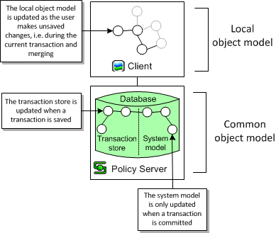
Each client's local object model is updated according to the common object model whenever a transaction is committed. The transaction may have been committed on the local host machine or on a remote client host.
Figure 3-5 illustrates the updating process that takes place when transactions are committed.
Figure 3-5 Updating the Object Models on Commit
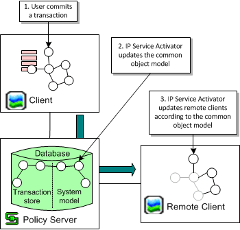
When a transaction is committed, IP Service Activator compares the common object model to each user interface's local object model and resolves any inconsistencies by removing them from the local object model.
Note:
A user with unsaved changes may lose those changes if they conflict with changes that have been committed to the common object model.As part of the common object model, IP Service Activator maintains a transaction store which holds pending, scheduled and committed transactions. The store is updated whenever a transaction is saved or its status changes.
Figure 3-6 illustrates where the transaction store sits in the common object model within the Policy server host.
You can view the content of the transaction store on the System tab in the Transactions folder in the Hierarchy pane on the client, as shown in Figure 3-7.
The system model section of the common object model is only updated with a transaction's changes when the transaction is committed, as illustrated in Figure 3-8.
You can create, commit, save and schedule, merge and unmerge, and delete transactions. For more information about working with transactions, see IP Service Activator User's Guide.
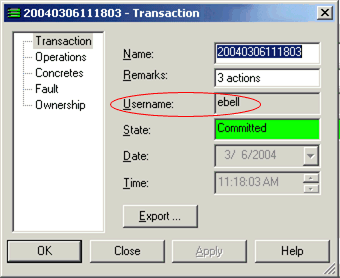
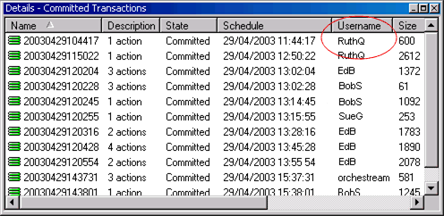
There are three ways to check which user created a transaction. You can:
Open the relevant transaction's properties dialog box and check the Username field on the Transaction property page, as shown in Figure 3-9.
Figure 3-9 The Username Field on the Transaction Property Page
List all transaction details in the Details pane of the Committed Transactions folder on the System tab, as shown in Figure 3-10.
Figure 3-10 The Username Column on the Details Pane
List the audit trail details in the System Logs folder on the System tab, as shown in Figure 3-11.
Figure 3-11 The Username Column on the Audit Trail Log Details Pane

You can select a single transaction or multiple transactions listed in the Details pane and select an action to perform on them. For example, you can merge a number of transactions in one step by multi-selecting them and selecting Merge from the pop-up menu. Where several transactions are selected, IP Service Activator processes them in the order in which they were selected.
When you commit changes in the IP Service Activator client and commit the transaction, several success or failure paths exist. This section describes some example paths.
When services are successfully activated by the Network Processor, their representations in the client (the Concretes) become ”Installed”.
When one or more concretes fail the Service Model (SM) or the Device Model (DM) validation rules, a fault (Critical or Error) is raised against the service and the invalid concretes affected by that transaction are rejected. The fault message includes ”Configuration failed validation” and the validation rule that has been violated.
For example, in Figure 3-12, two validation rules have been violated:
The MQC PHB includes shaping and other actions (for example, CBWFQ) at the same level. To correct this problem, a second MQC PHB including the other actions should be nested within the MQC PHB with shaping.
The MQC PHB includes queuing weight values that exceed the bandwidth of an interface. To correct this problem, either the queuing weight value should be reduced, the interface bandwidth increased, or if neither is possible, this MQC PHB should be disabled for this interface.
When one or more concretes fail the DM Schema validation, a fault (Error) is raised against the device itself and all the concretes affected by that transaction are rejected. The fault message includes ”Configuration failed validation (Validation failed ”, the data element, and its current value.
For example, in Figure 3-13, a schema validation rule has been violated. The MQC PHB includes traffic shaping with a CIR value of 88,000,000. The maximum value allowed for Traffic shaping CIR in a Frame Relay class is 45,000,000. To correct this problem, the CIR value should be reduced below the maximum value.
After the Network Processor completes the data analysis and it is successful, it generates the commands, connects to the device, and starts changing the device configuration. The response from the device is analyzed after each command:
Success response: If the device response includes a success message or no message at all (only a prompt) then the command is considered successful and the next one is issued. The success message list can be edited by the system administrator.
Error response: If the response from the device matches one of the known error patterns, then a fault (Error) is raised against the device itself, the invalid concretes affected by that transaction are rejected and any failed configuration is rolled back. The known error patterns (regular expressions) and their associated messages are listed below:
<cmd:errorPattern>
    <cmd:pattern>(?s).*Unrecognized command.*</cmd:pattern>
    <cmd:message>Unrecognized command</cmd:message>
</cmd:errorPattern>
<cmd:errorPattern>
    <cmd:pattern>(?s).*Wrong parameter found.*</cmd:pattern>
    <cmd:message>Wrong parameter found</cmd:message>
</cmd:errorPattern>
<cmd:errorPattern>
    <cmd:pattern>(?s).*Not supported on .*</cmd:pattern>
    <cmd:message>Not supported</cmd:message>
</cmd:errorPattern>
<cmd:errorPattern>
    <cmd:pattern>(?s).*Cannot change interface.*</cmd:pattern>
    <cmd:message>Cannot change interface</cmd:message>
</cmd:errorPattern>
<cmd:errorPattern>
    <cmd:pattern>(?s).* Incomplete command.*</cmd:pattern>
    <cmd:message>Incomplete command</cmd:message>
</cmd:errorPattern>
<cmd:errorPattern>
    <cmd:pattern>(?s).* Too many parameters.*</cmd:pattern>
    <cmd:message>Too many parameters</cmd:message>
</cmd:errorPattern>
The fault message includes the rejected command and the message associated to the error pattern. For example, in Figure 3-14, the transaction has been canceled and a fault raised when the device responded with ”Unrecognized command” to the ”qos max-bandwidth 56" command. Rollback has succeeded. To correct this problem, an investigation is necessary. The networkprocessor.log and the npcartridgeName.audit.log should be analyzed. The problem may be that the interface does not support this service.
Unknown error: If the response from the device does not match any success or error pattern, then the response is considered an unknown error. A fault (Error) is raised against the device itself, the invalid concretes affected by that transaction are rejected, and any failed configuration is rolled back. The fault message includes the rejected command and the actual message returned by the device. Note that due to fault display constraints, successive white space and new line characters are removed from the device response.
For example, in Figure 3-15, the transaction has been canceled and a fault raised when the device responded with ”QoS policy name is already applied” to the ”qos apply policy name outbound” command. Rollback has succeeded. To correct this problem, an investigation is necessary. The networkprocessor.log and the npcartridgeName.audit.log should be analyzed. This problem may be due to a conflict with manually installed configuration. The conflict must be manually resolved.
Rollback fails: If the rollback fails, then the fault is ”Critical”, as shown in Figure 3-16. This problem may be due to a conflict with manually installed configuration. The conflict must be manually resolved.
The invalid concretes should be disabled until the problem is corrected. The valid concretes can be disabled and re-enabled in order to have them successfully installed. For more information, see IP Service Activator System Administrator's Guide.
A concrete rule is an implementation of an abstract classification rule, policing rule or access rule that applies to a specific point in the network, i.e., at a particular interface. Each abstract rule set up can result in a number of concrete rules.
Each concrete rule has an associated status:
Inactive: the rule has been created, but has not yet been propagated to the proxy agents.
Disabled: the rule has been disabled by the user.
Active: the rule has been propagated to a proxy agent but is not yet installed on a device (for example, because the date and time limitations do not apply yet).
Conflict: the rule conflicts with an existing rule.
Installed: the rule has been successfully installed on the designated device.
Rejected: the proxy agent failed to install the rule; the rule has been discarded.
Uninstalled: the rule has been disabled by the user and successfully removed from the device.
UninstallFailed: the rule has been disabled by the user, but failed to be removed from the device. (A fault may be raised in the Faults pane.)
A concrete object search attempts to locate concrete objects that match the specified state. This means, for example, that you can search for all concrete access rules whose state is ’Installed' or search for VPNs whose state is ’Active'.
To search for concrete objects:
Do one of the following:
From the Tools menu, select Concrete Find.
In the Statistics Summary pane, double-click a cell.
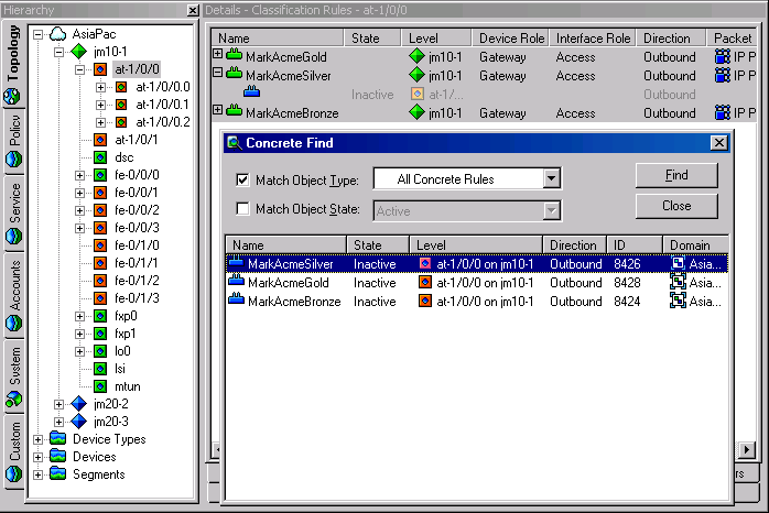
The Concrete Find dialog box appears, as in Figure 3-17.
Select the Match Object Type option and select a concrete object type from the drop-down menu.
(Optional) Select the Match Object State option and select a state from the drop-down menu.
The search is restricted by status.
Start the search by clicking Find.
IP Service Activator searches the object model for concrete objects that match the search criteria.
For each found concrete policy element, the following details are listed:
Name: the object's name
State: the object's status
Level: the name of the topology object at which the concrete object applies
Direction: whether the object is applied inbound or outbound to the interface
ID: the IP Service Activator object ID
Domain: the name of the domain
Double-click a found concrete object if you wish to view the point at which it applies in the Hierarchy pane and the details of the rule in the Details pane, as shown in Figure 3-18.
Figure 3-18 Displaying Hierarchy and Rule Details for a Found Object
Committing a transaction that propagates a rule, PHB group, or driver script to the network might result in the creation of concrete policy elements. A concrete policy element is an implementation of a defined rule, PHB group or driver script that applies to a specific point in the network, that is, at a particular interface, subinterface or VC endpoint. Each abstract or parent policy element set-up can result in a number of concrete policy elements.
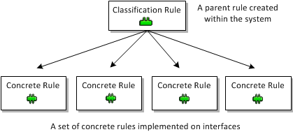
The following diagram illustrates the concept with a classification rule.
Figure 3-19 Abstract Classification Rule Resulting in Concrete Rules
You can list implemented rules, PHB groups, VPNs or driver scripts for a policy target in the Details pane. IP Service Activator indicates whether the policy element is abstract or concrete using colored backgrounds:
White background: an abstract policy element that has been set up on the selected object
Yellow background, indented: a concrete policy element that exists at the current or a lower level in the hierarchy
Gray background: an abstract policy element that has been inherited from a higher level object
Gray background, indented: a concrete policy element for an inherited policy element
The term abstract rule refers to the rule object created by the user as opposed to an implementation of the rule as installed in the network. A concrete rule is an implementation of a created classification rule, policing rule or access rule that is installed at a specific point in the network, that is, at a particular interface, sub-interface or VC endpoint. Each abstract or parent rule set up can result in a number of concrete rules.
An abstract rule might have a status of active or disabled. The status of an abstract rule is indicated by the appearance of its icon in the Details pane. See the IP Service Activator online Help for abstract rule status icons.
A concrete rule is an implementation of an abstract classification rule, policing rule or access rule that applies to a specific point in the network, i.e. at a particular interface. Each abstract rule set up can result in a number of concrete rules.
A concrete rule may have the following status values:
Inactive: the rule has been applied to an interface but has not yet been propagated to proxy agents.
Active: the rule has been propagated to a proxy agent but is not installed on a device at present.
Conflict: the rule conflicts with an existing rule or fails validation, for example, the action performed by a rule is not supported by an interface.
Rejected: the proxy agent failed to install the rule and it has been discarded.
Installed: the rule has been successfully installed on the designated device.
The concrete activation status allows flow-though applications of IP Service Activator to reliably track the progress of any IP Service Activator transaction.
The concrete activation status directly indicates whether a transaction's configuration changes, corresponding to each individual concrete, have been successfully activated on the network. The system maintains the concrete activation status for all client transactions including those committed or scheduled through the client and the OIM.
The activation status of a concrete object can be one of the following values:
Inactive: Concrete is not yet submitted.
Active: Activation is in progress. Passed indicates that the device is in sync with the current version of the service. Not Available indicates that no audit information is available.
Installed (Installed): The concrete is installed and is in sync with the current IP Service Activator model.
Installed (Installed): The concrete is installed, but no audit information is available.
Conflict: The current version of the concrete is in conflict with system capabilities and validation rules. Passed indicates that the device is in sync with the previous version of the service. Not Available indicates that no audit information is available.
Rejected: The current version of the concrete is in conflict with device validation rules. Passed indicates that the device is in sync with the previous version of the service. Not Available indicates that no audit information is available.
Disabled: Concrete was removed from the device. The audit should not report any configuration for this service.
Mismatched (Active): Activation is in progress. The audit indicates that the device is out of sync with the current IP Service Activator model.
Mismatched (Conflict): The current version of the concrete is in conflict with system capabilities and validation rules. The audit indicates that the device is out of sync with the previous version of the service.
Mismatched (Rejected): The current version of the concrete is in conflict with device validation rules. The audit indicates that the device is out of sync with the previous version of the service.
Mismatched (Installed): The concrete is installed, but is out of sync with the current IP Service Activator model.
By default, this feature is turned off. You must be aware of the following if you are turning this feature on:
When the concrete audit state feature is turned on, you must not perform any configuration changes affecting a device that is undergoing a device audit. Your changes can be lost if:
A device audit is in progress. (This results in an update of the Audit State of the device and its concretes.)
You make a change to the device configuration, or to any object within the device (interface, sub-interface, VC), or to any service object that affects concretes on the device.
If the device audit updates the Audit State of the concretes before the user commits the configuration changes, the user sees a message that they need to reenter their changes.
The concrete audit state feature is described in detail in the IP Service Activator online Help.
To turn on the Concrete Audit State feature:
Open the default.properties file.
Set the value of suppressAuditFeedback to False.
To turn off the Concrete Audit State feature:
Open the default.properties file.
Set the value of suppressAuditFeedback to True.
Note:
If the suppressAuditFeedback field does not appear in default.properties, add it manually. When the suppressAuditFeedback field does not appear, its value defaults to True (the feature is suppressed).When a per-service audit is initiated with the suppressAuditFeedback property set to False, the concrete audit states, and device audit state will be updated as in a full audit of the device. The generated per-service audit report is filtered using the IDs in the filter list.
If no concrete PHB groups are listed for an abstract PHB group, check the following:
The correct device and interface roles have been associated with the PHB group and assigned to the relevant policy targets.
Devices to which the PHB group should apply are managed.
IP Service Activator applies only one concrete PHB group to an interface. An abstract PHB group that has been applied at a lower level in the hierarchy overrides any PHB groups that have been applied at a higher level. A concrete standard PHB group that configures FRTS or ATM traffic shaping can be installed on an interface that has a concrete MQC PHB group whose mechanisms do not conflict with the standard PHB group.