| Oracle® Communications IP Service Activator QoS User’s Guide Release 7.2 E47716-01 |
|
|
PDF · Mobi · ePub |
| Oracle® Communications IP Service Activator QoS User’s Guide Release 7.2 E47716-01 |
|
|
PDF · Mobi · ePub |
This chapter provides some examples that illustrate Oracle Communications IP Service Activator's ability to apply policy at any point in the network and at any network component. This chapter:
Demonstrates how to target policy to the appropriate points in the network using roles
Shows how to apply policy to a VC endpoint
Illustrates the use of classifications and classification groups in rules
This example looks at QoS requirements across the core network and examines IP Service Activator's solution at one point in the network.
The requirements are as follows:
Provide two service packages, Premium and Basic
Support a range of customers
Ensure that bandwidth restrictions are applied to incoming and outgoing customer traffic
Maintain traffic flow in the core network
In both the Premium and the Basic service packages there are three classes of service – Gold, Silver and Bronze. The bandwidth percentage allocated to each CoS differs between service package:
Premium traffic receives 30% Gold, 30% Silver, 40% Bronze
Basic traffic receives 10% Gold, 40% Silver, 50% Bronze
Traffic entering the core network must be restricted to a bandwidth limit agreed on a per-customer basis. Links coming into the core differ in their bandwidth capacity.
These requirements are illustrated in Figure 8-1.
From the requirements, it is possible to identify three variables that affect policy:
Service package
Bandwidth capacity of the link
Customer
These variables dictate the roles that must be created to target policy to the appropriate points in the network. Ideally, three sets of roles would be created to support these variables. However, IP Service Activator allows a maximum of one system and/or one user-defined role to be assigned to a policy element (though you can assign one system and any number of user-defined roles to a policy target). In the roles we create, therefore, service package and bandwidth will be combined into a single role.
The roles to be defined are:
One role per service package/link size combination
One role per customer
The following solution, shown in Figure 8-2, focuses on a subsection of the network.
The tasks to be performed at each device can be defined as follows:
CE2:
Classify customer traffic before it enters the core network
Police outbound traffic to enforce bandwidth restrictions, per CoS
Apply Class-Based-WFQ (CB-WFQ) queuing mechanism to regulate traffic flow
PE2:
Police PE-CE traffic
Apply CB-WFQ queuing mechanism
P1:
Apply WRED queuing mechanism
After creating the appropriate roles, rules and PHB groups and applying them to the network, the roles and policy applied to CE2, PE2 and P1 are illustrated in Figure 8-3.
One of the advantages of IP Service Activator's role-based application of policy is the ability to assign roles to any network component, including sub-interfaces and VC endpoints. This enables you to apply policy to a sub-interface or VC endpoint independent of its parent interface.
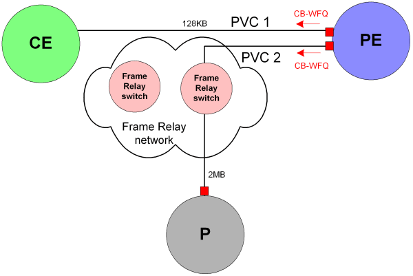
In this example, two VC endpoints on the same device are connected to two Permanent Virtual Circuits (PVC) that have different bandwidth capacity. CB-WFQ must be applied to both PVCs, with bandwidth weight defined in Kbits/s.
Figure 8-4 presents a physical representation of the relevant network section.
Figure 8-4 Network With Policy Applied at VC Endpoint

To take account of each PVC's bandwidth capacity, two PHB groups must be created and each PHB group targeted at the correct VC endpoint. This can be achieved by assigning a different role to each VC endpoint and associating the relevant role with the correct PHB group.
Figure 8-5 shows the logical network setup, with PHB groups defined and targeted at the appropriate VC endpoint using roles:
A classification provides a means of categorizing traffic according to its source and destination and traffic type. You can create standalone classifications and/or group a number of classifications to form a classification group. Members of a classification group do not need to share the same source and destination point or traffic type. Classifications and/or classification groups can be associated with a rule to define the traffic to which it applies.
In this example a set of Web-based application servers supply information to employees. Employees also have Internet access. The requirement is to apply a different CoS treatment to traffic to and from the application servers and the Internet.
The network setup is shown in Figure 8-6.
Note:
Traffic originating from both the Web-based application servers and the Internet has source port number 80.The example solution uses a classification group and a standalone classification within the classification rules that mark traffic from these sources:
A classification group holds five classifications that categorize traffic by IP address and port number
A standalone classification categorizes traffic by port number only
Two classification rules are created:
Web_application: marks traffic from the Web-based application servers. This rule is associated with the classification group.
Internet_traffic: marks traffic by port 80 only. This rule is associated with the standalone classification.
The solution is shown in Figure 8-7.
At the CE device, rules must be applied in the following order:
Web_application
Internet_traffic
Rule order is significant at this point as the interface handles both Web-based application traffic and Internet traffic. Therefore, the most specific rule must be applied first (classifying by both IP address and port number) before the more general rule (port number only). If the rules are applied in the incorrect order, both Web-based application traffic and Internet traffic will be classified by the Internet_traffic rule as both use port 80.