| Oracle® Big Data Appliance Owner's Guide Release 1 (1.1) Part Number E36161-06 |
|
|
PDF · Mobi · ePub |
| Oracle® Big Data Appliance Owner's Guide Release 1 (1.1) Part Number E36161-06 |
|
|
PDF · Mobi · ePub |
This chapter describes the network requirements for Oracle Big Data Appliance. This chapter contains these sections:
Oracle Big Data Appliance includes 18 servers and the equipment to connect the servers to your network. The network connections allow the servers to be administered remotely and allow clients to connect to them. Use the information in this chapter to configure the environment for Oracle Big Data Appliance.
Each server has the following network components and interfaces:
1 Dual-port 4X QDR (40 Gbps) InfiniBand Host Channel Adapter network interface card
1 Ethernet port for Oracle Integrated Lights Out Manager v3.0 for remote management
1 Gigabit Ethernet port
The installation process automatically discovers whether each Sun Network QDR InfiniBand Gateway Switch has at least one 10 GbE connection. If they all do, then two virtual network interface cards (VNICs) are configured for each server: one for each switch bonded as bondeth0 in active/passive failover mode. The VNICs are assigned automatically to the available 10 GbE connections in round-robin fashion. For example, if each switch has three available 10 GbE connections, then the VNIC on server 1 is assigned to 10 GbE port 1, server 2 to port 2, server 3 to port 3, server 4 to port 1, and so on.
All VNICs are assigned to the same default virtual local area network (VLAN). To assign different VLANs to different VNICs, you must delete the initial VNICs and manually create your own.
Additional configuration, such as defining multiple VLANs or enabling routing, may be required for the switch to operate properly in your environment. If additional configuration is needed, then your network administrator must perform the necessary configuration steps during installation of Oracle Big Data Appliance.
To deploy Oracle Big Data Appliance, ensure that your network meets the minimum requirements. Oracle Big Data Appliance uses three networks. Each network must be on a distinct and separate subnet from the others. These are the network descriptions:
Administrative network: This 1 gigabit Ethernet (GbE) network connects to your existing administrative network and is used to administer all components of Oracle Big Data Appliance. It connects the servers, Oracle ILOM, and switches connected to the Ethernet switch in the rack.
There are two uplinks to the administrative network:
From the Ethernet switch in the rack
From the KVM switch in the rack
Each server has two network interfaces for administration. One provides administrative access to the operating system through the eth0 Ethernet interface, and the other provides access to the Integrated Lights Out Manager through the Oracle ILOM Ethernet interface. Oracle Big Data Appliance is delivered with the eth0 and ILOM interfaces connected to the Ethernet switch on the rack. Do not use the eth0 interface on the servers for client network traffic. Cabling or configuration changes to these interfaces are not permitted.
Client access network: This 10 GbE network connects the servers though the gateway switches to your existing client network and is used for client access to the servers. Client applications access the software through this network by using Single Client Access Name (SCAN).
There are two Sun Network QDR InfiniBand Gateway Switches in the rack. Each switch supports 1 to 8 connections for client access for a total of up to 16 client network connections. For failover, you must have at least one connection from each switch and scale up according to your requirements for loading data and providing client access.
InfiniBand private network: This network connects the servers by using the InfiniBand switches on the rack and the bondib0 interface. This nonroutable network is fully contained in Oracle Big Data Appliance and does not connect to your existing network. This network is automatically configured during installation.
Note:
All networks must be on distinct and separate subnets from each other.The servers are configured on the network as follows:
eth0: Provides access to the operating system using the administrative network.
bondeth0: Provides access to the server using the client access network. The SCAN addresses are defined on this interface.
ILOM: Provides access to Oracle Integrated Lights Out Manager (ILOM) using the administrative network.
Figure 3-1 shows the network diagram. Use the preinstall-checkip.sh script to verify the cable connections when cabling Oracle Big Data Appliance to the existing network. See "Checking for Network Errors".
Figure 3-1 Network Diagram for Oracle Big Data Appliance
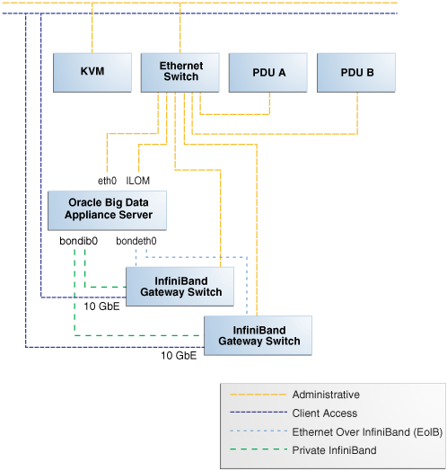
Each of the two Sun Network QDR InfiniBand Gateway Switches in Oracle Big Data Appliance has eight 10 GbE ports. The two switches enable you to create up to 16 10 GbE connections for each rack. You can determine how many connections to create based on the bandwidth needed for the client network. For proper functioning, at least one of the eight ports of each gateway switch must have an active connection to the site's 10 GbE network.
Physical Ethernet connections are created only between the site network and the gateway switches. The Oracle Big Data Appliance servers are connected only by InfiniBand to those switches. Each server has two InfiniBand connections, one to each gateway switch, in an active backup mode; only the active InfiniBand connection is used for all InfiniBand traffic to that server. If that connection fails, it immediately fails over to the other connection.
Half of the Oracle Big Data Appliance servers have active connections to one gateway switch, and the other half have active connections to the other gateway switch. Inside Oracle Big Data Appliance, the client network traffic is transported over those InfiniBand connections using the Ethernet over InfiniBand (EoIB) protocol. As a result, each Oracle Big Data Appliance server has two virtual NICs (VNICs) that are bonded in the same active backup mode. Each VNIC is assigned a specific port on the gateway switch. If a switch has only one 10 GbE connection, then all VNICs for that switch point to the same port. If a switch has multiple connections, then the VNICs are spread across those ports in round-robin fashion.
For example, if you create three 10 GbE uplinks from each gateway switch, then the client network traffic from the servers is handled by the switches as shown in the following table:
| Server Number | Active Link | Backup Link |
|---|---|---|
| 1 to 3 | GW Switch 1 Link 1 | GW Switch 2 Link 1 |
| 4 to 6 | GW Switch 1 Link 2 | GW Switch 2 Link 2 |
| ... | ... | ... |
| 16 to 18 | GW Switch 2 Link 3 | GW Switch 1 Link 3 |
Depending on the number of 10 GbE connections, the client network traffic for multiple servers may be sent across the same physical 10 GbE connection. The maximum number of connections provides 160 gigabits per second (Gbps) of client network bandwidth to Oracle Big Data Appliance.
Although you can create up to eight 10 GbE connections for each gateway switch, its physical ports are 40 Gbps quad small form-factor pluggable (QSFP) ports. Each gateway switch has two of these physical ports reserved for 10 GbE connectivity. The ports are equipped with QSFP transceivers that take an optical cable with an MTP/MPO connector. On the site network side are typically 10 Gbps ports with SFP+ transceivers that take LC connectors. For these connections, you can use splitter cables that have a single male MTP/MPO connector on one end and four pairs of LC connectors on the other end. Each 10 Gbps SFP+ transceiver takes a duplex LC connector for a total of four pairs. Thus, you can use a single splitter cable to create up to four 10 GbE connections. However, all four duplex LC connectors do not require a connection to the site network.
The splitter cables are not provided with Oracle Big Data Appliance and must be ordered separately from Oracle. They are available in lengths of 10, 20, and 50 meters. Oracle recommends that you order the SFP+ transceivers used at the site end of the 10 GbE network from the same manufacturer as the 10 GbE switch.
If your data center does not have a 10 GbE infrastructure, you can still connect Oracle Big Data Appliance to it by using an external switch that supports both 10 GbE (or 40 GbE) and 1 GbE. The Sun Network 10 GbE Switch 72p and numerous third-party switches provide this capability. You can connect the Sun Network QDR InfiniBand Gateway Switches to a 10 GbE or 40 GbE port and connect the data center to a 1 GbE port in the external switch.
When multiple Oracle Big Data Appliance racks are connected to form a single Hadoop cluster, Oracle strongly recommends that you spread the 10 GbE connections across the switches in different racks. Every gateway switch in every rack must have at least one 10 GbE connection. Oracle does not recommend that the 10 GbE connections to the switches in a single rack be used for all the Oracle Big Data Appliance servers in all the racks, although that configuration may be possible.
This initial network configuration is set at the factory for Oracle Big Data Appliance:
Gateway: 192.168.1.254 in all devices as required
Subnet Mask: 255.255.255.0 in all devices as required
IP Address Range: 192.168.1.1 to 192.168.1.211
Table 3-1 lists the default IP addresses for Oracle Big Data Appliance.
Table 3-1 Default IP Addresses for Oracle Big Data Appliance
| Host | Administrative IP Addresses | Oracle ILOM IP Addresses | InfiniBand Bonded IP Addresses |
|---|---|---|---|
|
bda18 |
|
|
|
|
bda17 |
|
|
|
|
bda16 |
|
|
|
|
bda15 |
|
|
|
|
bda14 |
|
|
|
|
bda13 |
|
|
|
|
bda12 |
|
|
|
|
bda11 |
|
|
|
|
bda10 |
|
|
|
|
bdasw-ib3 |
|
-- |
-- |
|
KVM Tray |
-- |
-- |
-- |
|
KVM Switch |
-- |
-- |
-- |
|
Cisco Switch |
|
-- |
-- |
|
bdasw-ib2 |
|
-- |
-- |
|
bda09 |
|
|
|
|
bda08 |
|
|
|
|
bda07 |
|
|
|
|
bda06 |
|
|
|
|
bda05 |
|
|
|
|
bda04 |
|
|
|
|
bda03 |
|
|
|
|
bda02 |
|
|
|
|
bda01 |
|
|
|
|
bdasw-ib1 |
|
-- |
-- |
|
PDU A |
|
-- |
-- |
|
PDU B |
|
-- |
-- |
Table 3-2 identifies the port numbers used by Oracle Big Data Appliance software. Ensure that these ports are free before you configure the network.
Table 3-2 Oracle Big Data Appliance Port Numbers
| Port | Used by |
|---|---|
|
22 |
ssh |
|
80 |
yumrepos (only during installation) |
|
111 |
portmap |
|
668 |
rpc.statd |
|
3306 |
MySQL Database |
|
5000 |
Oracle NoSQL Database registration |
|
5001 |
Oracle NoSQL Database administration |
|
5010 to 5020 |
Oracle NoSQL Database processes |
|
6481 |
xinetd (service tag) |
|
8139 |
Puppet nodes |
|
8140 |
Puppet parent |
|
20910 |
Oracle Data Integrator agent |
|
30920 |
Automated Service Monitor (ASM) |
Table 3-3 lists the ports used by Cloudera's Distribution including Apache Hadoop (CDH). For additional details about these port assignments, go to the Cloudera website at
http://ccp.cloudera.com/display/CDHDOC/Configuring+Ports+for+CDH3
| Port | Component | Service | Access |
|---|---|---|---|
|
0 |
HDFS |
Thrift Plugin DataNode |
-- |
|
0 |
MapReduce |
TaskTracker |
Localhost |
|
1004 |
HDFS |
Secure DataNode |
External |
|
1006 |
HDFS |
Secure DataNode |
External |
|
2181 |
HBase |
HQuorumPeer |
-- |
|
2181 |
ZooKeeper |
Server |
External |
|
2888 |
HBase |
HQuorumPeer |
-- |
|
2888 |
ZooKeeper |
Server |
Internal |
|
3181 |
Flume |
ZooKeeper Server |
-- |
|
3182 |
Flume |
ZooKeeper Server |
-- |
|
3183 |
Flume |
ZooKeeper Server |
-- |
|
3888 |
HBase |
HQuorumPeer |
-- |
|
3888 |
ZooKeeper |
Server |
Internal |
|
4181 |
ZooKeeper |
Server |
Peer |
|
8001 |
Hue |
Job Submission Server |
Internal |
|
8002 |
Hue |
Beeswax Server |
Internal |
|
8003 |
Hue |
Beeswax Metastore |
Internal |
|
8005 |
Oozie |
Server |
Internal |
|
8020 |
HDFS |
NameNode |
External |
|
8021 |
MapReduce |
JobTracker |
External |
|
8080 |
HBase |
REST Service |
External |
|
8088 |
Hue |
Server |
External |
|
9083 |
Hive |
Metastore |
External |
|
9090 |
HBase |
ThriftServer |
External |
|
9290 |
MapReduce |
JobTracker Thrift Plugin |
Internal |
|
10000 |
Hive |
HiveServer |
External |
|
10090 |
HDFS |
Thrift Plugin NameNode |
-- |
|
10091 |
MapReduce |
JobTracker Authorization Plugin |
Internal |
|
10092 |
HDFS |
Authorization Plugin NameNode |
-- |
|
10094 |
Oozie |
Server Authorization Plugin |
Internal |
|
11000 |
Oozie |
Server |
External |
|
16000 |
Sqoop |
Metastore |
External |
|
35853 |
Flume |
Node |
-- |
|
35862 |
Flume |
Node |
-- |
|
35871 |
Flume |
Master |
-- |
|
35872 |
Flume |
Master |
-- |
|
45678 |
Flume |
Master |
-- |
|
50010 |
HDFS |
DataNode |
External |
|
50020 |
HDFS |
DataNode |
External |
|
50030 |
MapReduce |
JobTracker |
External |
|
50060 |
MapReduce |
TaskTracker |
External |
|
50070 |
HDFS |
NameNode |
External |
|
50075 |
HDFS |
DataNode |
External |
|
50090 |
HDFS |
Secondary NameNode |
Internal |
|
50470 |
HDFS |
Secure NameNode |
External |
|
50495 |
HDFS |
Secure Secondary NameNode |
Internal |
|
57890 |
Flume |
Master |
-- |
|
60000 |
HBase |
Master |
External |
|
60010 |
HBase |
Master |
External |
|
60020 |
HBase |
RegionServer |
External |
|
60030 |
HBase |
RegionServer |
External |
|
Copyright © 2012, 2013, Oracle and/or its affiliates. All rights reserved. Legal Notices |
|