H VSM5 FICON Configuration
The VSM5, provides greater capacity and throughput than the VSM4, while retaining its advantages over the VSM3. Table H-1 summarizes the VSM5 features.
| Feature | Description |
|---|---|
|
Host/Nearlink Interfaces |
Up to 16 (FICON only) |
|
RTDs supported |
Up to 32 through FICON directors (in 3490-emulation mode only), can be a mixture of the following: 9840B, 9840C, 9940B, T10000. |
|
LSMs supported |
9740, 9360, 4410, 9310, SL8500 , SL3000 |
|
Maximum VTDs per VTSS |
256 |
|
Maximum VTVs per VTSS |
300,000 |
VSM5 FICON VCF Card Options - Maximum 16 RTDs
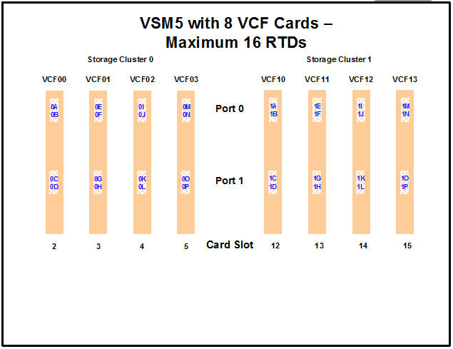
VSM5 is available only with VCF (FICON) cards in the following configurations for a maximum of 16 RTDs:
-
Figure H-1 shows a VSM5 with 8 VCF cards.
-
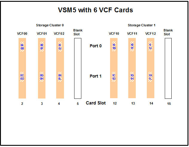
Figure H-2 shows a VSM5 with 6 VCF cards, 2 empty card slots.
-
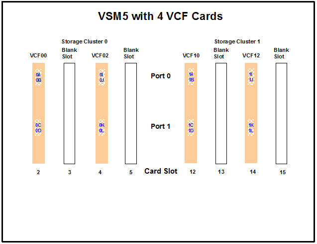
Figure H-3 shows a VSM5 with 4 VCF cards, 4 empty card slots.
Note:
In Figure H-1 through Figure H-3, the VCF cards must go in:-
All slots in an eight-VCF card configuration.
-
Slots 2, 3, 4, 13, 14, and 15 in a six-VCF card configuration.
-
Slots 2, 4, 14, and 15 in a four-VCF card configuration.
-
VSM5 FICON VCF Card Options - Maximum 32 RTDs
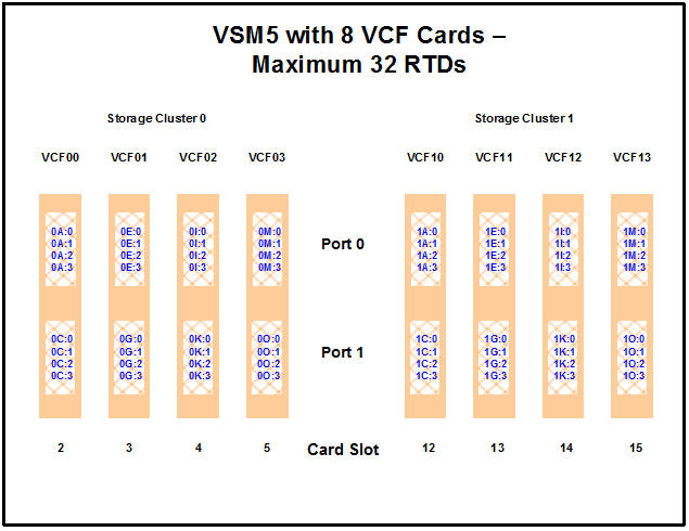
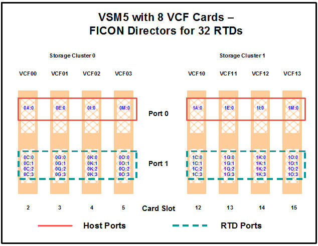
VSM5 is available only with 8 VCF (FICON) cards in the configuration for a maximum of 32 RTDs shown in Figure H-4. For more information on device addressing, see "RTD/CLINK Addresses - Maximum 32 RTDs."
FICON Port Processing
FICON ports processing is as follows:
-
FICON ports are controlled by a FICON Interface processor (FIP) and there can be only a total of 14 Nearlink FIPs (for maximum of 16 RTDs supported) or 28 Nearlink FIPs (for maximum of 32 RTDs supported).
-
For a VSM5, each FIP can operate with only one of two modes, which is set at the VTSS DOP:
-
Host Mode. In Host Mode, ports can connect to the host CPU channels, including through Director(s) or channel extenders. A port in Host Mode can also serve as a CLINK terminator.
-
Nearlink Mode. In Nearlink Mode, ports can connect to an RTD. A port in Nearlink Mode can also serve as a CLINK originator.
-
For clustering, you need an originator port in Nearlink mode on one VTSS connected through a CLINK to a terminator port in Host mode on the other VTSS.
-
-
In Figure H-1 through Figure H-4, the ports are shown with their channel interface identifiers where all ports are enabled. For more information on device addressing, see "RTD/CLINK Addresses - Maximum 32 RTDs."
Each FICON port can attach to up to 4 RTDs, or up to 4 CLINKs, or up to 4 RTD/CLINK combinations through a FICON director or supported switch (in FICON mode). Note that, as shown in these figures, each FICON port has multiple device addresses only if the port is connected to a FICON director which is then connected to multiple devices.
Note:
With microcode level D02.06.00.00 or higher, multiple Nearlink device connections through a FICON switch or Director on the same port now allow:-
Up to a total of 16 simultaneous NearLink I/O transfers, which can be spread across multiple targets on as many as 14 NearLink ports.
-
Up to a total of 2 simultaneous NearLink I/O transfers are allowed per port.
-
-
Each host FICON channel supports 64 logical paths (times 16 logical units). However, in HCD:
-
From a single MVS host, you can only define 8 channels (CHPIDs) running to a single control unit (single VSM5).
-
You use the CNTLUNIT statement to define each VSM5 as 16 3490 control unit images.
-
You use the IODEVICE statement to define the 16 VTDs that are associated with each 3490 control unit image.
Caution:
In bi-directional clustering, each CLINK must be attached to the same Storage Cluster on each VTSS, which is a requirement. Failure to configure in this manner can produce Replicate, Channel, and Communication errors. For more information and examples, refer to the ELS Disaster Recovery and Offsite Data Management Guide.
-
FICON Port Operations Best Practices
For FICON, Best Practices for optimizing port operations are shown in Table H-2.
Table H-2 Optimizing VSM5 FICON Port Operations
| Configuration - FICON port attached to a FICON Director | Best Practices |
|---|---|
|
Multiple CLINKs (up to 4) |
Attach a maximum of 2 because each port allows two active operations. Note, however, that these operations share the bandwidth of the port. |
|
CLINK and RTD combinations |
An advantage if you attach one CLINK originator/one RTD per director, because both can be active. |
|
Up to 4 RTDs |
An advantage for the following:
|
VSM5 FICON Front-End and Back-End Configuration Examples
For VSM5s, look at an examples of VCF card configurations and implementation in "VSM5 with 8 VCF Cards, FICON Directors for 32 RTDs."
For a VSM5 host gen example, see "IOCP Example for Single MVS Host Connected to a VSM5 Using FICON Directors."
Implementing Support for Maximum of 32 RTDs
-
Ensure that your system has the Maximum 32 RTDs requirements described in Table H-3.
-
Use CONFIG GLOBAL to enable support for maximum of 32 RTDs.
CONFIG GLOBAL MAXRTDS=32
Note:
Enabling support for a maximum of 32 RTDs does not require CONFIG RESET. However, regressing from 32 RTDs supported to 16 RTDs supported does require CONFIG RESET. -
Update your CONFIG RTD and CONFIG CLINK statements as required. For more information, see:
-
"VSM5 Configuration Example: 8 VCF Cards, FICON Directors, 32 RTDs"
Note:
The CONFIG utility RTD statement defines the RTDs connected to the VTSS. Specifically, the CONFIG RTD CHANIF parameter specifies the channel interface on the VTSS that communicates with the RTD.Similarly, the The CONFIG utility CLINK statement defines the channel interface for a CLINK originator using the CONFIG CLINK CHANIF parameter.
Code values for the CHANIF parameter as follows:
-
Regardless of whether the Maximum 32 RTDs feature is enabled, if you do not have a total of greater than 16 (RTDs, CLINK originators, or a combination of RTDs and CLINK originators) on that VTSS, you can use the ”old” addressing scheme on the CHANIF parameters.
-
If, however, the Maximum 32 RTDs feature is enabled and you have total of greater than 16 (RTDs, CLINK originators, or a combination of RTDs and CLINK originators) on that VTSS, you must use the ”new” addressing scheme on the corresponding CHANIF parameters.
-
-
Use the VSM5 DOP to reenter your RTD device addresses. See "VSM5 DOP Panels for Maximum 32 RTDs."
VSM5 Configuration Example: 8 VCF Cards, FICON Directors, 32 RTDs
Figure H-5 shows CONFIG channel interface identifiers for a VSM5 with 8 VCF cards and the Maximum 32 RTDs feature enabled. In this configuration, you have allocated 8 ports to RTDs and 8 ports to host connections. The RTD ports are all connected to FICON directors, each of which is attached to 4 RTDs, so the CHANIF identifiers for all 4 RTDs are shown on each port. This allows Back-End connection to 32 RTDs, although only one RTD per port/Director can be active at a time.
CONFIG Example for VSM5 FICON with 8 VCF Cards, FICON Directors, 32 RTDs
The following example shows CONFIG JCL to define the VSM5 configuration shown in Figure H-5.
//CREATECF EXEC PGM=SLUADMIN,PARM='MIXED'
//STEPLIB DD DSN=hlq.SEALINK,DISP=SHR
//SLSCNTL DD DSN=hlq.DBASEPRM,DISP=SHR
//SLSCNTL2 DD DSN=hlq.DBASESEC,DISP=SHR
//SLSSTBY DD DSN=hlq.DBASETBY,DISP=SHR
//SLSPRINT DD   SYSOUT=*
//SLSIN DD   *
 CONFIG
GLOBAL MAXVTV=32000 MVCFREE=40 VTVATTR=SCRATCH RECALWER=YES LOCKSTR=VTCS_LOCKS
REPLICAT=ALWAYS VTVPAGE=LARGE SYNCHREP=YES MAXRTDS=32
RECLAIM THRESHLD=70 MAXMVC=40  START=35
VTSS NAME=VSM501 LOW=70 HIGH=80 MAXMIG=8 RETAIN=5
 RTD  NAME=VSM52A00 DEVNO=2A00 CHANIF=0C:0
 RTD  NAME=VSM52A01 DEVNO=2A01 CHANIF=0C:1
 RTD  NAME=VSM52A02 DEVNO=2A02 CHANIF=0C:2
 RTD  NAME=VSM52A03 DEVNO=2A03 CHANIF=0C:3
 RTD  NAME=VSM52A04 DEVNO=2A04 CHANIF=0G:0
 RTD  NAME=VSM52A05 DEVNO=2A05 CHANIF=0G:1
 RTD  NAME=VSM52A06 DEVNO=2A06 CHANIF=0G:2
 RTD  NAME=VSM52A07 DEVNO=2A07 CHANIF=0G:3
 RTD  NAME=VSM52A08 DEVNO=2A08 CHANIF=0K:0
 RTD  NAME=VSM52A09 DEVNO=2A09 CHANIF=0K:1
 RTD  NAME=VSM52A0A DEVNO=2A0A CHANIF=0K:2
 RTD  NAME=VSM52A0B DEVNO=2A0B CHANIF=0K:3
 RTD  NAME=VSM52A0C DEVNO=2A0C CHANIF=0O:0
 RTD  NAME=VSM52A0D DEVNO=2A0D CHANIF=0O:1
 RTD  NAME=VSM52A0E DEVNO=2A0E CHANIF=0O:2
 RTD  NAME=VSM52A0F DEVNO=2A0F CHANIF=0O:3
 RTD  NAME=VSM53A00 DEVNO=3A00 CHANIF=1C:0
 RTD  NAME=VSM53A01 DEVNO=3A01 CHANIF=1C:1
 RTD  NAME=VSM53A02 DEVNO=3A02 CHANIF=1C:2
 RTD  NAME=VSM53A03 DEVNO=3A03 CHANIF=1C:3
 RTD  NAME=VSM53A04 DEVNO=3A04 CHANIF=1G:0
 RTD  NAME=VSM53A05 DEVNO=3A05 CHANIF=1G:1
 RTD  NAME=VSM53A06 DEVNO=3A06 CHANIF=1G:2
 RTD  NAME=VSM53A07 DEVNO=3A07 CHANIF=1G:3
 RTD  NAME=VSM53A08 DEVNO=3A08 CHANIF=1K:0
 RTD  NAME=VSM53A09 DEVNO=3A09 CHANIF=1K:1
 RTD  NAME=VSM53A0A DEVNO=3A0A CHANIF=1K:2
 RTD  NAME=VSM53A0B DEVNO=3A0B CHANIF=1K:3
 RTD  NAME=VSM53A0C DEVNO=3A0C CHANIF=1O:0
 RTD  NAME=VSM53A0D DEVNO=3A0D CHANIF=1O:1
 RTD  NAME=VSM53A0E DEVNO=3A0E CHANIF=1O:2
 RTD  NAME=VSM53A0F DEVNO=3A0F CHANIF=1O:3
 VTD LOW=9900 HIGH=99FF
VSM5 DOP Panels for Maximum 32 RTDs
The following VSM5 DOP panels are shown here.
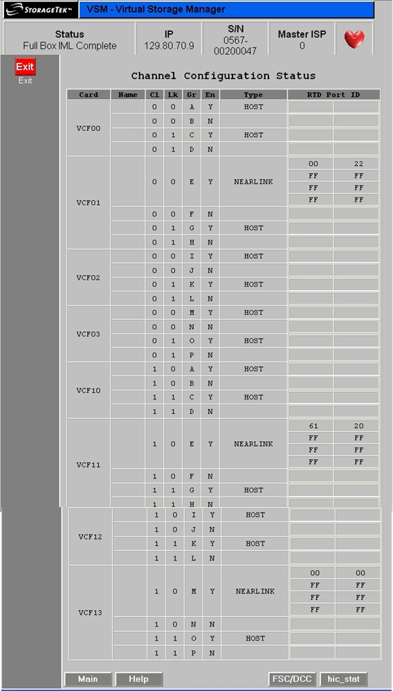
Channel Configuration Status Screen
To access the Channel Configuration Status screen, click the active Channel Status text field on the Configuration/Status Menu screen. See Figure H-6.
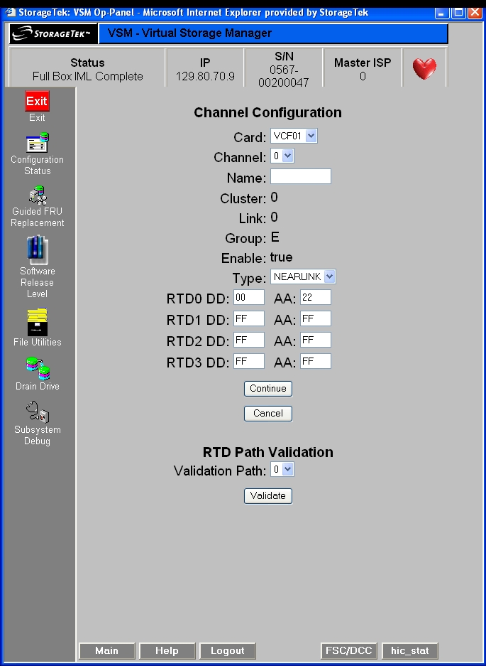
Channel Configuration and RTD Path Validation Screen
To access the Channel Configuration and RTD Path Validation screen, click on a VCF card shown on the Channel Configuration Status screen.
To set the configuration of a VCF card channel for host or Nearlink use, select the channel (0 or 1) and type from the pull-down lists, then click Continue to display a subscreen with the message Success, indicating the configuration change completed successfully. Click Cancel to undo changed settings and return to the Channel Configuration Status screen. See Figure H-7.
Real Tape Drive Status Screen
To access the Real Tape Drive Status screen, click the active Real Tape Drive Status text field on the Configuration / Status Menu screen, Figure H-8. To validate a real tape drive (RTD), click the active button in the Valid column for the RTD. The VTSS support facility validates the RTD, then displays a subscreen with the message RTD n was successfully validated. See hic_stat for details.
Note:
RTD configuration is preserved/restored across cold IML (EPO or CPD) but the links are reset and RTDs are offline until you vary them online with the VTCS VARY RTD ONLINE command.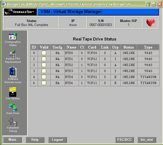
IOCP Example for Single MVS Host Connected to a VSM5 Using FICON Directors
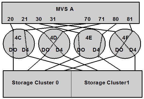
Figure H-9 shows a configuration diagram for a single MVS host connected to a VSM5 through FICON Directors, and the example that follows it shows IOCP statements for this configuration. Note that:
-
From MVSA, you define 8 CHPIDs, with each path switched in the FICON Director, for a total of 8 channels running to the VSM5.
-
You code 16 CNTLUNIT statements to define the VSM5 as 16 3490 images.
-
You code IODEVICE statement to define the 16 VTDs that are associated with each 3490 image.
-
If ESCON and FICON channels are configured to the same logical control unit, MVS issues message CBDG489I, which indicates that mixing ESCON and FICON channel paths on a logical control unit should be used only for the migration from ESCON to native FICON but should not be used permanently. This is a warning message only, and does not indicate an error.
ESCD4C CHPID PATH=(20,70),TYPE=FC,SWITCH=4C
ESCD4D CHPID PATH=(21,71),TYPE=FC,SWITCH=4D
ESCD4E CHPID PATH=(30,80),TYPE=FC,SWITCH=4E
ESCD4F CHPID PATH=(31,81),TYPE=FC,SWITCH=4F

CU1 CNTLUNIT CUNUMBR=001,
       PATH=(20,21,30,31,70,71,80,81),
       LINK=(D0,D4,D0,D4,D4,D0,D4,D0),
       UNIT=3490,CUADD=0,
       UNITADD=((00,16))

STRING1 IODEVICE ADDRESS=(0500,16),
       CUNUMBER=(001),
       UNIT=3490,
       UNITADD=00,STADET=Y

CU2 CNTLUNIT CUNUMBR=002,
       PATH=(20,21,30,31,70,71,80,81),
       LINK=(D0,D4,D0,D4,D4,D0,D4,D0),
       UNIT=3490,CUADD=1,
       UNITADD=((00,16))

STRING2 IODEVICE ADDRESS=(0510,16),
       CUNUMBER=(002),
       UNIT=3490,
       UNITADD=00,STADET=Y
       .
       .
       .

CU15 CNTLUNIT CUNUMBR=015,
       PATH=(20,21,30,31,70,71,80,81),
       LINK=(D0,D4,D0,D4,D4,D0,D4,D0),
       UNIT=3490,CUADD=E,
       UNITADD=((00,16))

STRING15 IODEVICE ADDRESS=(05E0,16),
       CUNUMBER=(015),
       UNIT=3490,
       UNITADD=00,STADET=Y

CU16 CNTLUNIT CUNUMBR=016,
       PATH=(20,21,30,31,70,71,80,81),
       LINK=(D0,D4,D0,D4,D4,D0,D4,D0),
       UNIT=3490,CUADD=F,
       UNITADD=((00,16))

STRING16 IODEVICE ADDRESS=(05F0,16),
       CUNUMBER=(016),
       UNIT=3490,
       UNITADD=00,STADET=Y
Tip: Unlike ESCON, FICON supports multiple active I/Os per channel. If the number of active VTDs is less than the number of channels configured to the VTSS, the I/Os to those VTDs may not be evenly spread across all the channels. As the number of active VTDs increases to be greater than the number of channels configured to the VTSS, the channel subsystem will spread the I/Os across all the channels. If it is desired to spread the I/Os across all of the channels even when only a few VTDs are active, it is necessary to use the preferred path feature to force the channel subsystem to spread the I/Os across the channels. The preferred path feature is specified using the PATH= parameter on the IODEVICE statement. When you specify preferred path on the IODEVICE statement, the channel subsystem always tries the preferred path first. If it is busy or unavailable, the channel subsystem next tries the channel path following the preferred path in the rotation order, and so on.
The following example shows IODEVICE statements for STRING1 without using preferred pathing.
STRING1 IODEVICE ADDRESS=(0500,16),
        CUNUMBER=(001),
        UNIT=3490,
        UNITADD=00,STADET=Y
The following example shows IODEVICE statements for STRING1 using preferred pathing. If you are using preferred pathing, you need to use these kind of IODEVICE statements for all paths, such as STRING2 through STRING16.
STRING10 IODEVICE ADDRESS=(0500,2),
       CUNUMBER=(001),
       UNIT=3490,
       UNITADD=00,STADET=Y,
       PATH=20

STRING12 IODEVICE ADDRESS=(0502,2),
       CUNUMBER=(001),
       UNIT=3490,
       UNITADD=00,STADET=Y,
       PATH=21

STRING14 IODEVICE ADDRESS=(0504,2),
       CUNUMBER=(001),
       UNIT=3490,
       UNITADD=00,STADET=Y,
       PATH=30

STRING16 IODEVICE ADDRESS=(0506,2),
       CUNUMBER=(001),
       UNIT=3490,
       UNITADD=00,STADET=Y,
       PATH=31

STRING18 IODEVICE ADDRESS=(0508,2),
       CUNUMBER=(001),
       UNIT=3490,
       UNITADD=00,STADET=Y,
       PATH=70

STRING1A IODEVICE ADDRESS=(050A,2),
       CUNUMBER=(001),
       UNIT=3490,
       UNITADD=00,STADET=Y,
       PATH=71

STRING1C IODEVICE ADDRESS=(050C,2),
       CUNUMBER=(001),
       UNIT=3490,
       UNITADD=00,STADET=Y,
       PATH=80

STRING1E IODEVICE ADDRESS=(050E,2),
       CUNUMBER=(001),
       UNIT=3490,
       UNITADD=00,STADET=Y,
       PATH=81