7 Using Multi-Data Centers
Oracle Access Management Access Manager allows for distribution of directory service data by providing identical copies of said data across more than one data center. Multiple data centers provide a scalable deployment model to support access management requirements for millions of users. The Multi-Data Center topology scales horizontally - within a single data center by clustering multiple nodes or across multiple data centers. This model provides load balancing as well as failover capabilities in the case that one of the data centers goes down.
This chapter contains the following sections.
7.1 Introducing Multi-Data Center
Large organizations using Access Manager 11g typically deploy their applications in multi-data centers to distribute load as well as address data recovery. Deploying multi-data centers configures single sign-on (SSO) between them and allows for the transfer of user session details transparently. The scope of a data center comprises protected applications, WebGate agents, Access Manager servers and other infrastructure entities including identity stores and databases. (Access Manager 11g supports scenarios where applications are distributed across two or more data centers.)
The Multi-Data Center approach supported by Access Manager is a Master-Clone deployment in which the first data center is specified as the Master and clone data centers mirror it. A Master Data Center is cloned using Test-to-Production (T2P) tools to create one or more child Data Centers. See Oracle Fusion Middleware Administrator's Guide for information on T2P. (The T2P utility is also used to replicate Access Manager domains used by data centers.) Figure 7-1 illustrates the Multi-Data Center system architecture.
Figure 7-1 Multi-Data Center System Architecture
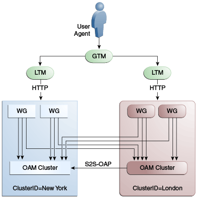
Description of "Figure 7-1 Multi-Data Center System Architecture"
A data center may include applications, data stores, load balancers and the like. Each data center includes a full Access Manager installation. The WebLogic Server domain will not span data centers. Global load balancers are configured to route HTTP traffic to the geographically closest data center. (No load balancers are used to manage Oracle Access Protocol traffic.) Additionally, they maintain user to data center affinity although session adoption allows for the creation of a user session based on the submission of a valid authentication cookie (OAM_ID) indicating that a session for the user already exists in another data center. (Session adoption may or may not involve re-authentication of the user.)
All applications are protected by WebGate agents configured against Access Manager clusters in the respective data centers. Every WebGate has a primary server and one or more secondary servers; WebGate agents in each data center have Access Manager server nodes from the same data center in the primary list and nodes from other data centers in the secondary list. It is still possible for a user request to be routed to a different data center when:
-
The data center goes down.
-
There is a load spike causing redistribution of traffic.
-
Certain applications are deployed in only one data center.
-
WebGates are configured to load balance within one data center but failover across data centers.
The following sections contain more information on how Multi-Data Center works and the topologies it supports.
7.1.1 Providing a Multi-Data Center Solution
The following sections contain information on how the Multi-Data Center solution is implemented.
7.1.1.1 Enhancing Cookies for Multi-Data Center
The following sections contain information on the SSO cookies enhanced and used by the Multi-Data Center.
7.1.1.1.1 OAM_ID Cookie
The OAM_ID cookie is the SSO cookie for Access Manager and holds the attributes required to enable the MDC behavior across all Data Centers. If a subsequent request from a user in the same SSO session is routed to a different Data Center in the Multi-Data Center topology, session adoption is triggered per the configured session adoption policies. Session adoption refers to the action of a Data Center creating a local user session based on the submission of a valid authentication cookie (OAM_ID) that indicates a session for the user exists in another other Data Center in the topology. (It may or may not involve re-authentication of the user.) When a user session is created in a Data Center, the OAM_ID cookie will be augmented/updated with the clusterid of the Data Center, a sessionid and the latest_visited_clusterid.
In Multi-Data Center deployments, OAM_ID is a host-scoped cookie. Its domain parameter is set to login.oracle.com, a virtual host name which is a singleton across data centers and is mapped by the global load balancer to the Access Manager servers in the Access Manager data center based on the load balancer level user traffic routing rules (for example, based on geographical affinity). The OAM_ID cookie is not accessible to applications other than the Access Manager servers.
7.1.1.1.2 OAMAuthn / ObSSO WebGate Cookies
OAMAuthn is the WebGate cookie for 11g and ObSSO is the WebGate cookie for 10g. On successful authentication and authorization, a user will be granted access to a protected resource. At that point, the browser will have a valid WebGate cookie with the clusterid:sessionid of the servicing Data Center. If authentication followed by authorization spans across multiple Data Centers, the Data Center authorizing the user request will trigger session adoption by retrieving the session's originating clusterid from the WebGate cookie. After adopting the session, a new session will be created in the current Data Center with the synced session details.
Note:
The WebGate cookie cannot be updated during authorization hence the newly createdsessionid cannot be persisted for future authorization references. In this case, the remote sessionid and the local sessionids are linked through session indexing. During a subsequent authorization call to a Data Center, a new session will be created when:
-
MDC is enabled.
-
A session matching the sessionid in the WebGate cookie is not present in the local Data Center.
-
There is no session with a Session Index that matches the sessionid in the WebGate cookie.
-
A valid session exists in the remote Data Center (based on the MDC SessionSync Policy).
In these instances, a new session is created in the local Data Center with a Session Index that refers to the sessionid in the WebGate cookie.
7.1.1.1.3 OAM_GITO (Global Inactivity Time Out) Cookie
OAM_GITO is a domain cookie set as an authorization response. The session details of the authentication process will be recorded in the OAM_ID cookie. If the authorization hops to a different Data Center, session adoption will occur by creating a new session in the Data Center servicing the authorization request and sets the session index of the new session as the incoming sessionid. Since subsequent authentication requests will only be aware of the clusterid:sessionid mapping available in the OAM_ID cookie, a session hop to a different Data Center for authorization will go unnoticed during the authentication request. To address this gap, an OAM_GITO cookie (which also facilitates timeout tracking across WebGate agents) is introduced.
During authorization, the OAM_GITO cookie is set as a domain cookie. For subsequent authentication requests, the contents of the OAM_GITO cookie will be read to determine the latest session information and the inactivity/idle time out values. The OAM_GITO cookie contains the following data.
-
Data Center Identifier
-
Session Identifier
-
User Identifier
-
Last Access Time
-
Token Creation Time
Note:
For the OAM_GITO cookie, all WebGates and Access Manager servers should share a common domain hierarchy. For example, if the server domain is.us.example.com then all WebGates must have (at least) .example.com as a common domain hierarchy; this enables the OAM_GITO cookie to be set with the .example.com domain.7.1.1.2 Session Adoption During Authorization
Multi-Data Center session adoption is supported during the authorization flow. After successful authentication, the OAMAuthn cookie will be augmented with the cluster ID details of the Data Center where the authentication has taken place. During authorization, if the request is routed to a different Data Center, the runtime does adequate checks to determine whether it is a Multi-Data Center scenario and looks for a valid remote session. If one is located, the Multi-Data Center session adoption process is triggered per the session adoption policies; a new session will be created in the Data Center servicing the authorization request.
Note:
Since OAMAuthn cookie updates are not supported during authorization, the newly created session's session index will be set to that of the incoming session ID.7.1.1.3 Session Indexing
During an authorization call to a Data Center, a new session will be created in the local Data Center with a Session Index that refers to the session identifier in the OAMAuth/ObSSO cookie. This will occur under the following conditions:
-
Session matching Session ID in the OAMAuth/ObSSO cookie is not present in the local Data Center.
-
MDC is enabled.
-
No session with Session Index matching Session ID in the OAMAuth/ObSSO cookie.
-
Valid Session exists in the remote Data Center based on the MDC SessionSync Policy.
7.1.2 Supported Multi-Data Center Topologies
Access Manager supports the following Multi-Data Center topologies.
-
An Active-Active topology is when Master and Clone data centers are exact replicas and active at the same time. They cater to different sets of users based on defined criteria; geography, for example. A load balancer routes traffic to the appropriate Data Center. See Section 7.1.2.1, "Active-Active Mode."
Note:
An Active-Active topology with agent failover is when an agent has Access Manager servers in one Data Center configured as primary and Access Manager servers in the other Data Centers configured as secondary to aid failover scenarios. -
An Active Standby-Passive topology is when the primary Data Center is operable and the clone Data Center is not but can be brought up within a reasonable time in cases when the primary data center fails. See Section 7.1.2.2, "Active Standby-Passive Mode."
-
Active–Hot Standby is when one of the Data Centers is in hot standby mode. In this case, the Data Center will not actively be used until the other Data Center goes down. See Section 7.1.2.3, "Active-Hot Standby."
7.1.2.1 Active-Active Mode
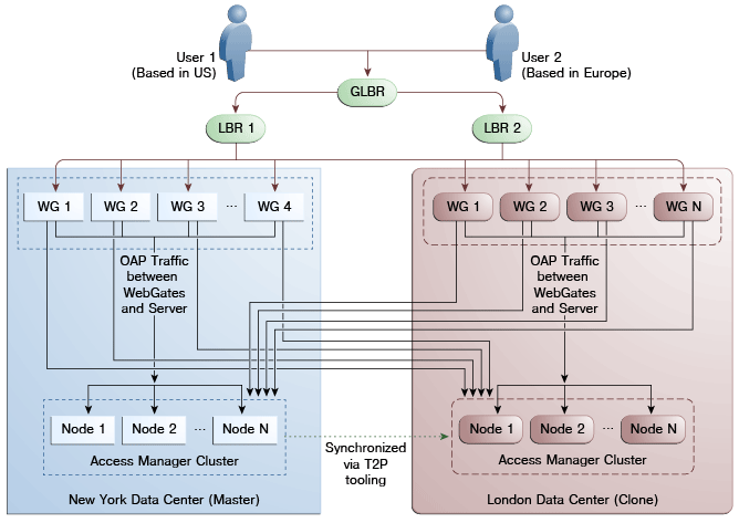
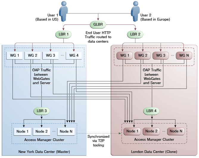
Figure 7-2 illustrates a Multi-Data Center set up in Active-Active mode during normal operations. The New York Data Center is designated as the Master and all policy and configuration changes are restricted to it. The London Data Center is designated as a Clone and uses T2P tooling and utilities to periodically synchronize data with the New York Data Center. The global load balancer is configured to route users in different geographical locations (US and Europe) to the appropriate data centers (New York or Europe) based on proximity to the data center (as opposed to proximity of the application being accessed). For example, all requests from US-based User 1 will be routed to the New York Data Center (NYDC) and all requests from Europe-based User 2 will be routed to the London Data Center (LDC).
Note:
The Access Manager clusters in this figure are independent and not part of the same Oracle WebLogic domain. WebLogic domains are not recommended to span across data centers.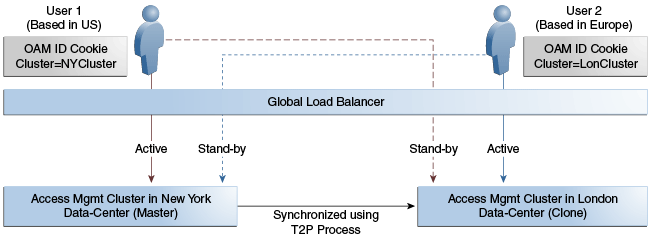
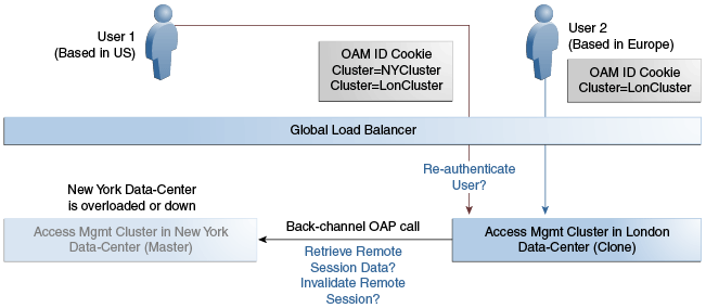
In this example, if NYDC was overloaded with requests, the global load balancer would start routing User 1 requests to the clone Access Manager cluster in LDC. The clone Access Manager cluster can tell (from the user's OAM ID cookie) that there is a valid session in the master cluster and would therefore create a new session without prompting for authentication or re-authentication. Further, the session adoption policy can be configured such that the clone Access Manager cluster would make a back-end request for session details from the master Access Manager cluster using the Oracle Access Protocol (OAP). The session adoption policy can also be configured to invalidate the remote session (the session in NYDC) so the user has a session only in one data center at a given time.
Figure 7-3 illustrates how a user might be rerouted if the Master cluster is overloaded or down. If the Master Access Manager cluster were to go completely down, the clone Access Manager cluster would try to obtain the session details of User 1 but since the latter would be completely inaccessible, User 1 would be forced to re-authenticate and establish a new session in the clone Access Manager cluster. In this case, any information stored in the previous session is lost.
7.1.2.2 Active Standby-Passive Mode
Active-Passive Mode is when one of the data centers is passive and can be brought up within a reasonable time in case the primary data center fails.
7.1.2.3 Active-Hot Standby
Active-Hot Standby Mode is when one of the data centers is in a hot standby mode. It will not actively cater to users until the other data center goes down.
7.1.3 Understanding Access Manager Security Modes for Multi-Data Center
The MDC relies on the Oracle Access Protocol (OAP) channel for the inter data center session management operations and back channel communication. The security mode of the MDC partner profile should match the security mode defined for the Access Manager server: OPEN, SIMPLE or CERT.
Note:
An MDC partner profile is exposed by each data center and used by other data centers to communicate with it. Registering an MDC partner is a two step process. Consider an MDC with three data centers. In DC1, expose an MDC partner profile by creating a 10g or 11g WebGate (DC1_MDC_Partner). Then, register DC1_MDC_Partner in DC2 and DC3 using addPartnerForMultiDataCentre. See Section 7.9.3, "addPartnerForMultiDataCentre" for details.7.1.3.1 OPEN Security Mode
This is the default mode of the Access Manager deployment. No configuration is needed. The following is a sample input properties file for use with the addPartnerForMultiDataCentre WLST command.
remoteDataCentreClusterId=
 <CLUSTER ID OF REMOTE DC FOR WHICH THE AGENT IS BEING ADDED>
oamMdcAgentId=
 <AGENT ID OF THE REGISTERED PARTNER IN datacenter ABOVE>
PrimaryHostPort=<fully-qualified-host-name:OAM-port>
 for example:PrimaryHostPort=adc.example.com:5575
SecondaryHostPort=<fully-qualified-host-name:OAM-port>
 for example:SecondaryHostPort=adc.example.com:5577
AccessClientPasswd=<ACCESS CLIENT PASSWORD OF oamMdcAgentId IN datacenter>
oamMdcSecurityMode=OPEN
agentVersion=<WEBGATE AGENT VERSION 10g or 11g>
#NA ----> Not Applicable
trustStorePath=NA
keyStorePath=NA
globalPassPhrase=NA
keystorePassword=NA
7.1.3.2 SIMPLE Security Mode
Follow the instructions in Appendix C, "Configuring Simple Mode Communication with Access Manager" to set up the Access Manager servers in SIMPLE mode. In short, create an MDC partner profile in each of the member data centers in SIMPLE mode, and add it to each of the other data centers. The following is a sample input properties file for use with the addPartnerForMultiDataCentre WLST command.
remoteDataCentreClusterId=
 <CLUSTER ID OF REMOTE DC FOR WHICH THE AGENT IS BEING ADDED>
oamMdcAgentId=<AGENT ID OF THE REGISTERED PARTNER IN datacenter ABOVE>
PrimaryHostPort=<fully-qualified-host-name:OAM-port>
 for example:PrimaryHostPort=adc.example.com:5575
SecondaryHostPort=<fully-qualified-host-name:OAM-port>
 for example:SecondaryHostPort=adc.example.com:5577
AccessClientPasswd=<ACCESS CLIENT PASSWORD OF oamMdcAgentId IN datacenter>
oamMdcSecurityMode=SIMPLE
agentVersion=<WEBGATE AGENT VERSION 10g or 11g>

#Copy the oamclient-truststore.jks & oamclient-keystore.jks from
#<DOMAIN_HOME>/output/webgate-ssl/ from 'datacenter with cluster ID #remoteDataCentreClusterId' above into the local DC say /scratch/MDCArtifacts/ and
#refer them in the below parameters

trustStorePath=</scratch/MDCArtifacts/oamclient-truststore.jks>
keyStorePath=</scratch/MDCArtifacts/oamclient-keystore.jks>

#Use the online WLST command displaySimpleModeGlobalPassphrase() to list
#the global passphrase in SIMPLE mode. Admins can also update this in the UI
#@ System Configuration-->Access Manager-->Access Manager Settings-->
#Access Protocol-->Simple Mode Configuration-->Global Passphrase.
#globalPassPhrase & keystorePassword are the same for SIMPLE mode

globalPassPhrase=<passphrase resulted in using the above steps>
keystorePassword=<same as globalPassPhrase>
7.1.3.3 CERT Security Mode
Follow the instructions in Appendix C, "Configuring Cert Mode Communication for Access Manager" to set up the Access Manager servers in CERT mode. In short, create an MDC partner in each of the member data centers in CERT mode, and generate the 'clientTrustStore.jks' and 'clientKeyStore.jks' keystores to be used by the MDC partner using the following procedure.
-
Run the following openssl command from a Linux command prompt to generate aaa_key.pem & aaa_req.pem.
openssl req -new -keyout aaa_key.pem -out aaa_req.pem -utf8Use the certreq command to generate the certificate and chain.
-
Create aaa_cert.pem using the following procedure.
-
Open aaa_req.pem in a text editor and copy the contents.
Exclude the trailing spaces from your selection.
-
Paste the copied text into Signcsr.
Include [-----BEGIN CERTIFICATE REQUEST----- and -----END CERTIFICATE REQUEST-----].
-
Copy the output into a text editor and save it as aaa_cert.pem.
-
-
Create aaa_chain using the following procedure.
-
Open certreq.
-
Click on chain.pem and copy/paste the contents into a text editor and save it as aaa_chain.pem.
Excluding traiing and leading spaces from your selection.
-
-
Encrypt the private key (aaa_key.pem) using the following command.
openssl rsa -in aaa_key.pem -passin pass: -out aaa_key.pem -passout pass:Welcome1 -des
The password used in this command must be defined as the access client password or agent key password while registering the MDC partner.
-
Copy aaa_key.pem, aaa_cert.pem and aaa_chain.pem to a temporary location.
For example, /tmp/clientCertArtifacts/
-
Convert aaa_cert.pem and aaa_key.pem into DER format using one of the following commands.
-openssl x509 -in /tmp/clientCertArtifatcs/aaa_cert.pem -inform PEM -out
 /tmp/clientCertArtifatcs/aaa_cert.der -outform DER;
-openssl pkcs8 -topk8 -nocrypt -in /tmp/clientCertArtifatcs/aaa_key.pem
 -inform PEM -out /tmp/clientCertArtifatcs/aaa_key.der -outform DER;
-
Import the aaa_key.der and aaa_cert.der into clientKeyStore.jks; and the aaa_chain.pem into clientTrustStore.jks with the below steps
-cd $IDM_HOME/oam/server/tools/importcert/;

-unzip importcert.zip;

-java -cp importcert.jar
 oracle.security.am.common.tools.importcerts.CertificateImport -keystore
 /tmp/clientCertArtifatcs/clientKeyStore.jks -privatekeyfile
 /tmp/clientCertArtifatcs/aaa_key.der -signedcertfile
 /tmp/clientCertArtifatcs/aaa_cert.der -storetype jks -genkeystore yes

-keytool -importcert -file /tmp/clientCertArtifatcs/aaa_chain.pem -trustcacerts
 -keystore /tmp/clientCertArtifatcs/clientTrustStore.jks -storetype JKS
Enter the keystore passwords when prompted. The password needs to be defined in the input properties file for the addPartnerForMultiDataCentre WLST command as well.
-
If not done when creating the certificates for the WebGate, import the aaa_key.der and aaa_cert.der formatted certificates into the .oamkeystore using the same Oracle provided importcert.jar used inthe previous step.
-java -cp importcert.jar
 oracle.security.am.common.tools.importcerts.CertificateImport
 -keystore /scratch/Oracle/Middleware/domains/
 base_domain/config/fmwconfig/.oamkeystore -privatekeyfile
 /tmp/clientCertArtifacts/aaa_key.der -signedcertfile
 /tmp/clientCertArtifacts/aaa_cert.der -alias mycertmode1 -storetype JCEKS
alias is the alias name defined when setting CERT mode in Access Manager.
The following is a sample input properties file for use with the addPartnerForMultiDataCentre WLST command.
remoteDataCentreClusterId=
 <CLUSTER ID OF REMOTE DC FOR WHICH THE AGENT IS BEING ADDED>
oamMdcAgentId=<AGENT ID OF THE REGISTERED PARTNER IN datacenter ABOVE>
PrimaryHostPort=<fully-qualified-host-name:OAM-port>
 for example:PrimaryHostPort=adc.example.com:5575
SecondaryHostPort=<fully-qualified-host-name:OAM-port>
 for example:SecondaryHostPort=adc.example.com:5577
AccessClientPasswd=<ACCESS CLIENT PASSWORD OF oamMdcAgentId IN datacenter>
oamMdcSecurityMode=CERT
agentVersion=<WEBGATE AGENT VERSION 10g or 11g>

trustStorePath=</tmp/clientCertArtifatcs/clientTrustStore.jks >
keyStorePath=</tmp/clientCertArtifatcs/clientKeyStore.jks >

globalPassPhrase=NA

#use keystore password used for generating keystore in the previous step
keystorePassword=<keystore password given while generating keystore>
7.2 Understanding Multi-Data Center Deployments
In a Multi-Data Center deployment, each data center will include a full Access Manager installation and WebLogic Server domains will not span the Data Centers. Global load balancers will maintain user to Data Center affinity although a user request may be routed to a different Data Center:
-
When the data center goes down.
-
When a load spike causes redistribution of traffic.
-
When each Data Center is not a mirror of the other. For example, certain applications may only be deployed in a single Data Center.
-
WebGates are configured to load balance within the Data Center and failover across Data Centers.
Figure 7-4 illustrates a basic Multi-Data Center deployment.
The following sections describe several deployment scenarios.
-
Session Adoption Without Re-authentication, Session Invalidation or Session Data Retrieval
-
Session Adoption Without Re-authentication But With Session Invalidation & Session Data Retrieval
-
Authentication & Authorization Requests Served By Different Data Centers
Note:
The OAP connection used for backchannel communication does not support load balancing or failover so a load balancer needs to be used.7.2.1 Session Adoption Without Re-authentication, Session Invalidation or Session Data Retrieval
The following scenario illustrates the flow when the Session Adoption Policy is configured without reauthentication, remote session invalidation and remote session data retrieval. It is assumed the user has affinity with DC1.
-
User is authenticated by DC1.
On successful authentication, the OAM_ID cookie is augmented with a unique data center identifier referencing DC1 and the user can access applications protected by Access Manager in DC1.
-
Upon accessing an application deployed in DC2, the user is routed to DC2 by a global load balancer.
-
Access Manager in DC2 is presented with the augmented OAM_ID cookie issued by DC1.
On successful validation, Access Manager in DC2 knows that this user has been routed from the remote DC1.
-
Access Manager in DC2 looks up the Session Adoption Policy.
The Session Adoption Policy is configured without reauthentication, remote session invalidation or remote session data retrieval.
-
Access Manager in DC2 creates a local user session using the information present in the DC1 OAM_ID cookie (lifetime, user) and re-initializes the static session information ($user responses).
-
Access Manager in DC2 updates the OAM_ID cookie with its data center identifier.
Data center chaining is also recorded in the OAM_ID cookie.
-
User then accesses an application protected by Access Manager in DC1 and is routed back to DC1 by the global load balancer.
-
Access Manager in DC1 is presented with the OAM_ID cookie issued by itself and updated by DC2.
On successful validation, Access Manager in DC1 knows that this user has sessions in both DC1 and DC2.
-
Access Manager in DC1 attempts to locate the session referenced in the OAM_ID cookie.
-
If found, the session in DC1 is updated.
-
If not found, Access Manager in DC1 looks up the Session Adoption Policy (also) configured without reauthentication, remote session invalidation and remote session data retrieval.
-
-
Access Manager in DC1 updates the OAM_ID cookie with its data center identifier and records data center chaining as previously in DC2.
7.2.2 Session Adoption Without Re-authentication But With Session Invalidation & Session Data Retrieval
The following scenario illustrates the flow when the Session Adoption Policy is configured without reauthentication but with remote session invalidation and remote session data retrieval. It is assumed the user has affinity with DC1.
-
User is authenticated by DC1.
On successful authentication, the OAM_ID cookie is augmented with a unique data center identifier referencing DC1.
-
Upon accessing an application deployed in DC2, the user is routed to DC2 by a global load balancer.
-
Access Manager in DC2 is presented with the augmented OAM_ID cookie issued by DC1.
On successful validation, Access Manager in DC2 knows that this user has been routed from the remote DC1.
-
Access Manager in DC2 looks up the Session Adoption Policy.
The Session Adoption Policy is configured without reauthentication but with remote session invalidation and remote session data retrieval.
-
Access Manager in DC2 makes a back-channel (OAP) call (containing the session identifier) to Access Manager in DC1 to retrieve session data.
The session on DC1 is terminated following data retrieval. If this step fails due to a bad session reference, a local session is created as documented in Section 7.2.1, "Session Adoption Without Re-authentication, Session Invalidation or Session Data Retrieval."
-
Access Manager in DC2 creates a local user session using the information present in the OAM_ID cookie (lifetime, user) and re-initializes the static session information ($user responses).
-
Access Manager in DC2 rewrites the OAM_ID cookie with its own data center identifier.
-
The user then accesses an application protected by Access Manager in DC1 and is routed to DC1 by the global load balancer.
-
Access Manager in DC1 is presented with the OAM_ID cookie issued by DC2.
On successful validation, Access Manager in DC1 knows that this user has sessions in DC2.
-
Access Manager in DC1 makes a back-channel (OAP) call (containing the session identifier) to Access Manager in DC2 to retrieve session data.
If the session is found, a session is created using the retrieved data. If it is not found, the OAM Server in DC1 creates a new session. The session on DC2 is terminated following data retrieval.
7.2.3 Session Adoption Without Re-authentication & Session Invalidation But With On-demand Session Data Retrieval
Multi-Data Center supports session adoption without re-authentication except that the no-local session are not terminated and the local session is created using session data retrieved from the remote DC. Note that the OAM_ID cookie is updated to include an attribute that indicates which data center is currently being accessed.
7.2.4 Authentication & Authorization Requests Served By Different Data Centers
Consider a scenario where an authentication request is served by the New York Data Center (NYDC) but the authorization request is presented to the London Data Center (LDC) because of user affinity. If Remote Session Termination is enabled, the scenario requires a combination of the OAM_ID cookie, the OamAuthn/ObSSO authorization cookie and the GITO cookie to perform the seamless Multi-Data Center operations. This flow (and Figure 7-5 following it) illustrates this. It is assumed that the user has affinity with NYDC.
-
Upon accessing APP1, a user is authenticated by NYDC.
On successful authentication, the OAM_ID cookie is augmented with a unique data center identifier referencing NYDC. The subsequent authorization call will be served by the primary server for the accessed resource, NYDC. Authorization generates the authorization cookie with the NYDC identifier (cluster-id) in it and the user is granted access to the APP1.
-
User attempts to access APP2 in LDC.
-
The Webgate for APP2 finds no valid session in LDC and initiates authentication.
Due to user affinity, the authentication request is routed to NYDC where seamless authentication occurs. The OamAuthn cookie contents are generated and shared with the APP2 Webgate.
-
The APP2 Webgate forwards the subsequent authorization request to APP2's primary server, LDC with the authorization cookie previously generated.
During authorization, LDC will determine that this is a Multi-Data Center scenario and a valid session is present in NYDC. In this case, authorization is accomplished by syncing the remote session as per the configured session adoption policies.
-
A new session is created in LDC during authorization and the incoming session id is set as the new session's index.
Subsequent authorization calls are honored as long as the session search by index returns a valid session in LDC. Each authorization will update the GITO cookie with the cluster-id, session-id and access time. The GITO cookie will be re-written as an authorization response each time.
lf a subsequent authentication request from the same user hits NYDC, it will use the information in the OAM_ID and GITO cookies to determine which Data Center has the most current session for the user. The Multi-Data Center flows are triggered seamlessly based on the configured Session Adoption policies.
Figure 7-5 Requests Served By Different Data Centers
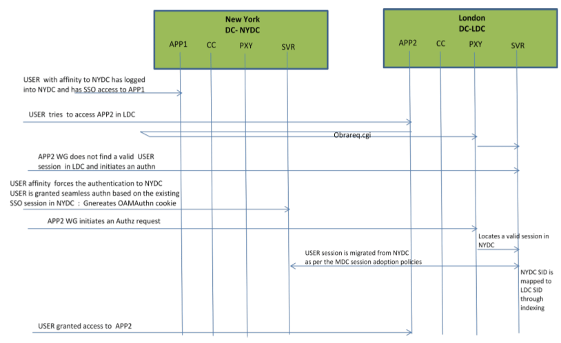
Description of "Figure 7-5 Requests Served By Different Data Centers"
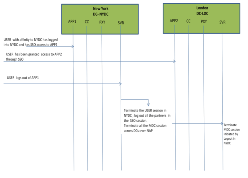
7.2.5 Logout and Session Invalidation
In Multi-Data Center scenarios, logout ensures that all server side sessions across Data Centers and all authentication cookies are cleared out. For session invalidation, termination of a session artifact over the back-channel will not remove the session cookie and state information maintained in the Webgates. However, the lack of a server session will result in an Authorization failure which will result in re-authentication. In the case of no session invalidation, the logout clears all server side sessions that are part of the current SSO session across Data Centers. This flow (and Figure 7-6 following it) illustrates logout. It is assumed that the user has affinity with NYDC.
-
User with affinity to NYDC gets access to APP1 after successful authentication with NYDC.
-
User attempts to access APP2.
At this point there is a user session in NYDC as well as LDC (refer to section 2.4.5) as part of SSO.
-
User logs out from APP1.
Due to affinity, the logout request will reach NYDC.
-
The NYDC server terminates the user's SSO session and logs out from all the SSO partners.
-
The NYDC server sends an OAP terminate session request to all relevant Data Centers associated with the SSO session - including LDC.
This results in clearing all user sessions associated with the SSO across Data Centers.
7.3 Before Deploying Multi-Data Centers
The following pre-requisites must be satisfied before deploying Multi-Data Centers.
-
All Data Center clusters must be front ended by a single Load Balancer. The load balancer should send all requests in a user session consistently to the same backend server (persistence, stickiness) and it should be route traffic geographically (geo-affinity).
-
Clocks on the machines in which Access Manager and agents are deployed must be in sync. Non-MDC Access Manager clusters require the clocks of WebGate agents be in sync with Access Manager servers. This requirement applies to the MDC as well. If the clocks are out of sync, token validations will not be consistent resulting in deviations from the expected behaviors regarding the token expiry interval, validity interval, timeouts and the like.
-
The identity stores in a Multi-Data Center topology must have the same Name.
-
The first Data Center is designated as Master and will be cloned (using T2P tools) for additional Data Centers.
-
All configuration and policy changes are propagated from the Master to the Clone using the WLST commands provided as part of the T2P Tooling.
-
Each Data Center is a separate WebLogic Domain and the install topology is the same.
-
Any firewall between these Data Centers must allow communication over the OAP channel between the data centers.
-
Partners (WebGates or agents) are anchored to a single Data Center. Partner registration is done at the individual Data Centers.
7.4 Deploying Multi-Data Centers
An Active-Active topology is when Master and Clone Data Centers are exact replicas of each other (including applications, data stores and the like). They are active at the same time and cater to different sets of users based on defined criteria - geography, for example. A load balancer routes traffic to the appropriate Data Center. Identical Access Manager clusters are deployed in both locales with New York designated as the Master and London as the Clone.
Note:
An Active-Active topology with agent failover is when an agent has Access Manager servers in one Data Center configured as primary and Access Manager servers in the other Data Centers configured as secondary to aid failover scenarios.Figure 7-7 illustrates the topology for a Multi-Data Center deployment in Active-Active mode. The New York Data Center is designated as the Master and all policy and configuration changes are restricted to it. The London Data Center is designated as a Clone and uses T2P tooling and utilities to periodically synchronize data with the New York Data Center. The global load balancer is configured to route users in different geographical locations (US and Europe) to the appropriate data centers (New York or Europe) based on proximity to the data center (as opposed to proximity of the application being accessed). For example, all requests from US-based User 1 will be routed to the New York Data Center (NYDC) and all requests from Europe-based User 2 will be routed to the London Data Center (LDC).
The Global Load Balancer is configured for session stickiness so once a user has been assigned to a particular data center, all subsequent requests from that user would be routed to the same data center. In this example, User 1 will always be routed to the New York Data Center and User 2 to the London Data Center.
User requests in the respective data centers are intercepted by different WebGates depending on the application being accessed. Each WebGate has the various nodes of the Access Manager cluster within the same data center configured as its primary servers. In this case, the WebGates load balance and failover the local data center.
Note:
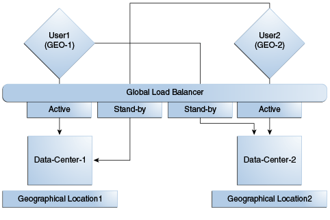
Administrators have the flexibility to configure the primary servers for every WebGate in different orders based on load characteristics. Running monitoring scripts in each data center will detect if any of the Access Manager components – the WebGates or the servers – are unresponsive so administrators can reconfigure the load balancers to direct user traffic to a different data center.Any number of Clone data centers can be configured to distribute the load across the globe. The only condition is that all Clone data centers are synchronized from a single Master using T2P. Figure 7-8 below depicts an Active-Active Multi-Data Center deployment across five data centers.
Figure 7-8 Active-Active Topology Across Multiple Data Centers
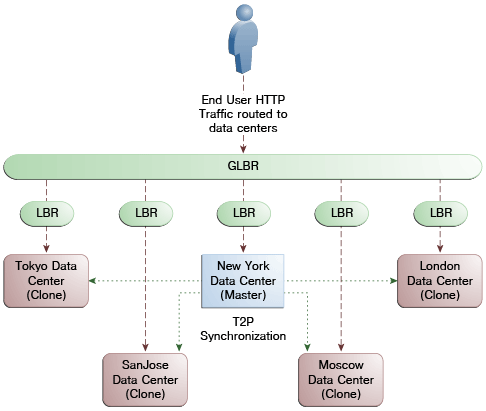
Description of "Figure 7-8 Active-Active Topology Across Multiple Data Centers"
7.5 Load Balancing Between Access Management Components
The topology described earlier shows global and local load balancers for routing the end user HTTP traffic to various data centers. Additionally, customers can choose to deploy load balancers between the access manager components to simplify the configuration of the access manager components by using virtual host names. For example, instead of configuring the primary servers in each WebGate in the NYDC as ssonode1.ny.acme.com, ssonode2.ny.acme.com and so on, they can all point to a single virtual hostname like sso.ny.acme.com and the load balancer will resolve the DNS to direct them to various nodes of the cluster. However, while introducing a load balancer between Access Manager components, there are a few constraining requirements to keep in mind.
-
OAP connections are persistent and need to be kept open for a configurable duration even while idle.
-
The WebGates need to be configured to recycle their connections proactively prior to the Load Balancer terminating the connections, unless the Load Balancer is capable of sending TCP resets to both the Webgate and the server ensuring clean connection cleanup.
-
The Load Balancer should distribute the OAP connection uniformly across the active Access Manager Servers for each WebGate (distributing the OAP connections according the source IP), otherwise a load imbalance may occur.
Figure 7-9 illustrates a variation of the deployment topology with local load balancers (LBR 3 and LBR 4) front ending the clusters in each data center. These local load balancers can be Oracle HTTP Servers (OHS). The OAP traffic still flows between the WebGates and the Access Manager clusters within the data center but the load balancers perform the DNS routing to facilitate the use of virtual host names.
Figure 7-9 Load Balancing Access Manager Components
Description of "Figure 7-9 Load Balancing Access Manager Components"
Figure 7-10 illustrates a second variation of the deployment topology with the introduction of a global load balancer (GLBR2) to front end local load balancers (LBR3 and LBR4). In this case, the hostnames can be virtualized not just within the data center but across the data centers. The WebGates in each data center would be configured to load balance locally but fail over remotely. One key benefit of this topology is that it guarantees high availability at all layers of the stack. Even if the entire Access Manager cluster in a data center were to go down, the WebGates in that data center would fail over to the Access Manager cluster in the other data center.
Figure 7-10 Global Load Balancer Front Ends Local Load Balancer
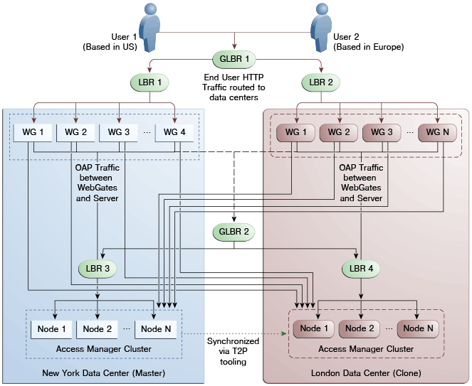
Description of "Figure 7-10 Global Load Balancer Front Ends Local Load Balancer"
For information on monitoring Access Manager server health with a load balancer in use, see Section 12.7, "Monitoring the Health of an Access Manager Server."
7.6 Setting Up A Multi-Data Center
The MDC feature is disabled by default. To deploy an Access Manager MDC, start with an Access Manager cluster, set all MDC global configurations and designate the cluster as the Master Data Center. This procedure includes running the commands documented in Section 7.9, "WLST Commands for Multi-Data Centers."
Note:
See Oracle Fusion Middleware WebLogic Scripting Tool Command Reference for information on the WebLogic Scripting Tool.From the Master, clone the required number of Data Centers using the T2P process explained in the following documents.
-
See Oracle Fusion Middleware Administrator's Guide for information on T2P when using WebLogic Server.
-
See Oracle Fusion Middleware Third-Party Application Server Guide for Oracle Identity and Access Management for information on T2P when using Websphere Server.
The following procedure contains more details.
-
Set up the primary Access Manager Data Center and designate it as the Master.
This Multi-Data Center can be an existing Access Manager cluster or a vanilla installation. The Access Manager bootstrap assigns a unique
clusterIdto the Access Manager cluster. To set a custom clusterId, use thesetMultiDataCentreClusterNameWLST command documented in Section 7.9.7, "setMultiDataCentreClusterName."-
Perform the basic configurations.
This includes setting up the LDAP store, and configuring the security mode [SIMPLE/CERT].
-
Enable MDC by running the
enableMultiDataCentreModeWLST command.This applies the global configurations.
-
Configure the global load balancer.
-
Validate the MDC configuration by running the
validateMDCConfig()WLST command. -
Restart the Admin server.
-
Designate this Access Manager cluster as the Master Data Center.
enableMultiDataCentreMode sets an Access Manager cluster as Master, by default. To explicitly set the DC type, use the
setMultiDataCenterTypeWLST command. -
Deploy any applications and WebGates to the Data Center.
-
-
Clone the required number of clusters from the Master Data Center using the T2P process.
Note:
This step contains the cloning procedure for R2PS1. If using R2PS2, do the following:-
Run the rcu to create the schema required for Access Manager on the target data center database.
-
Skip step a.
-
Export the Access Manager and OPSS data by running the copyConfig command (as designated below) with the additional
-opssDataExport trueargument../copyConfig.sh -javaHome $JAVA_HOME -archiveLoc $T2P_HOME/oamt2pConfig.jar -sourceDomainLoc $WL_DOMAIN_HOME -sourceMWHomeLoc $MW_HOME -domainHostName name.example.com -domainPortNum 7001 -domainAdminUserName weblogic -domainAdminPassword $T2P_HOME/t2p_domain_pass.txt -silent true -ldl $T2P_HOME/oam_cln_log_config -opssDataExport true -debug true;
-
R2PS1 Step Only: Before you begin cloning an Access Manager R2PS1 data center, move the OPSS data from the source database to the target. Instructions for performing this procedure can be found in the Oracle Fusion Middleware Administrator's Guide.
-
After moving the OPSS data, copy the Access Manager from the source test machine to the target production server using the following three sets of commands.
On the Source Test machine, run:
export JAVA_HOME=/scratch/11gR2_Refresh/jRockit;
export MW_HOME=/scratch/R2PS2RC4Refresh/Middleware;
export T2P_HOME=/scratch/R2PS2RC4Refresh/T2P;
export WL_DOMAIN_HOME=$MW_HOME/user_projects/domains/base2_domain;

cd $MW_HOME/oracle_common/bin/;

  Note : For the copyBinary command the Admin and
  managed servers can be running or stopped

./copyBinary.sh -javaHome $JAVA_HOME -archiveLoc $T2P_HOME/oamt2pbin.jar
 -sourceMWHomeLoc $MW_HOME -idw true
 -ipl $MW_HOME/oracle_common/oraInst.loc
 -silent true -ldl $T2P_HOME/oam_cln_log;

  Note : For the copyConfig command the Admin and managed servers
  should be up and running; see note above when running R2PS2

./copyConfig.sh -javaHome $JAVA_HOME -archiveLoc $T2P_HOME/oamt2pConfig.jar
 -sourceDomainLoc $WL_DOMAIN_HOME -sourceMWHomeLoc
 $MW_HOME -domainHostName name.example.com -domainPortNum 7001
 -domainAdminUserName weblogic
 -domainAdminPassword $T2P_HOME/t2p_domain_pass.txt
 -silent true -ldl $T2P_HOME/oam_cln_log_config -debug true;

cp $MW_HOME/oracle_common/bin/pasteBinary.sh $T2P_HOME;
cp $MW_HOME/oracle_common/jlib/cloningclient.jar $T2P_HOME;
cp $MW_HOME/oracle_common/oraInst.loc $T2P_HOME;
On the target production server, run:
export JAVA_HOME=/scratch/PSFE_T2P_FINAL/jRockit/jRockit;
export MW_HOME=/scratch/PSFE_T2P_FINAL/Middleware;
export T2P_HOME=/scratch/PSFE_T2P_FINAL/T2P/T2P;
export WL_DOMAIN_HOME=
 /scratch/PSFE_T2P_FINAL/Middleware/user_projects/domains/base15_domain;
Make a directory and copy the contents of $T2P_HOME on the source machine to this directory. Use the appropriate copy command for the target environment.
mkdir -p $T2P_HOME
cp -r /net/slc02ozn/$T2P_HOME/* $T2P_HOME
cd $T2P_HOME

./pasteBinary.sh -javaHome $JAVA_HOME -al /scratch/T2P_FIX/oamt2pbin.jar
 -tmw $MW_HOME -silent true -idw true -esp false
 -ipl /scratch/T2P_FIX/oraInst.loc -ldl /scratch/T2P_FIX/oam_cln_log_p
 -silent true

cd $MW_HOME/oracle_common/bin

./extractMovePlan.sh -javaHome $JAVA_HOME -al $T2P_HOME/oamt2pConfig.jar
 -planDirLoc $T2P_HOME/moveplan/

cp $T2P_HOME/moveplan/moveplan.xml $T2P_HOME/moveplan/moveplan.org
Also on the target production server, before running this pasteConfig command, the moveplan.xml just extracted must be updated with the host and port details of the Target Machine as well as the DATA SOURCE details. Be sure that the moveplan modifications are reviewed carefully and the Target machine details are verified before running the following pasteConfig command.
./pasteConfig.sh -javaHome $JAVA_HOME
 -archiveLoc $T2P_HOME/oamt2pConfig.jar -targetMWHomeLoc $MW_HOME
 -targetDomainLoc $WL_DOMAIN_HOME
 -movePlanLoc $T2P_HOME/moveplan/moveplan.xml
 -domainAdminPassword $T2P_HOME/t2p_domain_pass.txt
 -ldl $T2P_HOME/oam_cln_log_paste_p -silent true
After these steps, the Access Manager Clone Cluster is set up and the Admin Server started and running. The managed servers can be started as needed.
-
-
Perform the following configurations for the clones created in the previous step.
-
Set a unique
clusterIdfor all Clone Data Centers using thesetMultiDataCentreClusterNameWLST command.setMultiDataCentreClusterName(clusterName="LonCluster")
The T2P process copies the Master
clusterIdto all clones. -
Use the
addPartnerForMultiDataCentreWLST command to configure and register the MDC partners in all of the member Data Centers (Master and Clones).Note:
An MDC partner profile is exposed by each data center and used by other data centers to communicate with it. Registering an MDC partner is a two step process. Consider an MDC with three data centers. In DC1, expose an MDC partner profile by creating a 10g or 11g WebGate (DC1_MDC_Partner). Then, register DC1_MDC_Partner in DC2 and DC3 using addPartnerForMultiDataCentre. See Section 7.9.3, "addPartnerForMultiDataCentre" for details. -
Open the necessary firewall ports in the Clone Data Centers to allow back channel communication (required for onDemand session data retrieval).
-
Deploy any applications and WebGates to the Clone Data Centers.
Note:
In cases of load balancing based on the user's affinity, the load balancer decides the target Data Center against which the authentication will occur so an authentication request initiated by a given WebGate can reach any of the member Data Centers. Thus, the WebGate profiles need to be uniformly present across the member Data Centers even though the applications are deployed selectively across Data Centers. To sync this WebGate specific data following T2P, use the exportPartners/importPartners and exportPolicy/importPolicy WLST commands.
-
-
Distribute the changes to all the member Data Centers using T2P commands.
-
Mark the member Data Centers as write protected by designating them as Clone and read-only using the
setMultiDataCenterTypeandsetMultiDataCenterWriteWLST commands.
7.7 Syncing Multi-Data Centers
The Multi-Data Center infrastructure can be configured to keep Access Manager data synchronized across multiple data centers. Previously, replication was addressed using T2P tooling to setup the Master and Clones and any further changes are applied using the WLST commands. In this 11gR2 release introduces Automated Policy Synchromization (APS), an automated replication mechanism that removes administrator and manual intervention from the data synchronization process. (The T2P tooling and WLST command procedure used previous to this release is still available.
Note:
Policy, system configuration and partner metadata will to be synchronizedWhen syncing data centers using APS, the following may occur:
-
Establishment of a replication agreement with the registration of one data center as a replication clone and another in a separate geographical location as its master; the changes are pulled and applied to the clone.
-
Definition of data center specific configurations which may not be replicated across data centers.
-
Tracking of Access Manager configuration changes in each data center and querying the current replication state in any of the data centers.
-
Generation of a changelog which can be applied in the context of a similar setup running in another data center.
-
Trigger of a pull from a master data center if there is a need; for example, if automated replication fails.
-
Replication of Access Manager configuration artifacts in Master-Clone model.
The following sections contain additional details.
7.7.1 How Automated Policy Synchronizaton Works
Automated Policy Synchronization works in a master-clone topology. In this topology, multiple clones pull changes from a single master. One Data Center is defined by the administrator as the master and one or more other Data Centers work as clones. The administrator makes changes to the master and the clones replicate them. Only master to clone replication is supported; changes to clones will not be replicated back to the master.
Note:
Multi-master replication is not supported.To partake in APS, the supplier data center (initiater of the replication) and the clone data center (receiver of the changes) must have a Replication Agreement stored in the Access Manager data store. (APS is optional; administrator initiated import and export based replication is still available.) Table 7-1 documents the states in which APS can be deployed.
Table 7-1 Automated Policy Synchronization - States of Replica
| State | Definition |
|---|---|
|
Active |
An Access Manager domain (inlcuding Admin and managed servers) is setup to serve access requests. In an active state, the Access Manager server provides the web access management functionalities without additional MDC features. |
|
Bootstrapping |
This state is optional for some Data Centers; for example, the first one in an MDC topology. A Data Center goes through this intermediate state when added to an existing MDC topology. The new DC contacts the master and bootstraps itself to the same state. The bootstrap includes synchronizing the server keys, policy artifacts, partners, and system configuration. After completion of bootstrapping, the DC will be Replication Ready. |
|
Replication Ready |
In this state, MDC is enabled, the DC is made part of the topology, and the replication service is enabled. Once enabled, a clone can be registered with the master via a Replication Agreement. Once established, clone DCs can query and start pulling changelogs from the master. |
Figure 7-11 illustrates the flow of Automated Policy Synchronization.
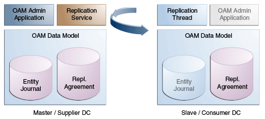
7.7.2 Understanding the Replication Agreement
APS replicates configuration changes (defined as journals) from a Master node to Clone nodes. On receiving the journals, each node updates it's configuration to match the journal and remains in the synchronized state. The nodes, though, need to enter a replication agreement to receive change journals.
When a new data center is added to an existing MDC topology, it has to bootstrap itself to be in sync with the existing data centers. This bootstrap operation will get the current Access Manager policies, system configuration, partner metadata and server keys for the existing MDC topology. After the bootstrap operation, the new data center captures the last change sequence number from the topology's master so that during replication it can be used to determine the current state.
Note:
Automated bootstrap is the ideal scenaro but (in R2PS2) you can execute T2P tooling first to ensure the Master configuration and Clones are in the same state. Following this, APS can be enabled and setup for sync. See Enabling the Replication Service for details.To establish replication, the clone data center must know the supplier's change log sequence number. If the data center is added to the topology on 'day 0' and the replication agreement was created on 'day N', there is a need to bootstrap again. To avoid this and to keep the flow simple, creating a replication agreement should take care of the bootstrap and actual replication agreement creation. See Enabling the Replication Service for details.
7.7.3 Enabling the Replication Service
The Replication Service is a set of REST API. The binaries are installed as part of the Access Manager application and deployed in AdminServer. It is disabled by default but can be enabled by setting the oracle.oam.EnableMDCReplication property to true. After enabling the service, create a pull model Replication Agreement between the clone data center and the master. The clone polls for changes from the master as long as the replication agreement is valid for it. The master will respond to the clone's request as long as it finds a valid replication agreement. The clone pulls changes from the master and applies them locally.
Note:
To verify that the replication REST services are available, access the following hello REST end point.curl -u <user> 'https://oam1.example.com:7002/oam/services/rest/_ replication/hello'
The following sections contain details on how to use the REST API provided by Access Manager. They need to be executed at the master data center's end point.
7.7.3.1 Setting Up Replication Using REST
The example in this section assumes that DC1 is the master located at oam1.oracle.com. DC2 is cloned from DC1 using the T2P process and is located at oam2.oracle.com.
Note:
For replication, the partnerInfo.properties file used for WLST input should have an additionalRESTEndpoint property (sample below). Its value is the HTTP endpoint for invoking replication related REST services. See addPartnerForMultiDataCentre.
remoteDataCentreClusterId=DC1
oamMdcAgentId=DC1Partner
PrimaryHostPort=dc1.oracle.com:5575
SecondaryHostPort=dc1.oracle.com:5576
AccessClientPasswd=secret
oamMdcSecurityMode=OPEN
trustStorePath=NA
keyStorePath=NA
globalPassPhrase=NA
keystorePassword=NA
agentVersion=11g
RESTEndpoint=https://oam1.oracle.com:443
This following REST request will:
-
Insert an entry in the Master's replication agreement store that contains details regarding the clone that wants to pull changes.
-
Insert an entry in the Clone's replication agreement store that contains details regarding the master and values like the poll interval.
POST http://oam1.oracle.com/oam/services/rest/_replication/setup HTTP/1.1
Content-Type: application/json
{"name":"DC12DC2", "source":"DC1","target":"DC2","documentType":"ENTITY"}
Note:
The REST end point can be an HTTP or HTTPS URL. HTTPS is preferred.In response to this REST request, the Master provides its starting sequence number for the changelog repository. The starting sequence number is used to update the Clone's replication agreement to the sequence number from which the replication will occur. The identifier returned is used for replication related queries.
{"enabled":"true","identifier":"201312040602298762","ok":"true","pollInterval":"60","startingSequenceNumber":"10","state":"READY"}
In the previous example, all records before the value of the startingSequenceNumber (10) are not available. It is implicit that the bootstrap happened before creating the replication agreement and the Clone can start pulling changes from sequence number 10. The Clone also has an entry created in its local replication table which keeps track of the last sequence number
Note:
The Weblogic user and password will be used for authentication when replication polling happens from the Clone to the Master. To call a different user for replication, a valid basic authorization header can be provided for the Clone. In the following example, 'replicationuser' and 'secret' are user and password (respectively) and "BASIC cmVwbGljYXRpb251c2VyOnNlY3JldA==" is the basic header (base64 encrypted with user and password) to be used for REST calls. User details will be seeded to both the Master and Clone.
curl -u weblogic:welcome1 -H 'Content-Type: application/json'
 -X POST 'http://adc1140321.example.com:7001/oam/services/rest
 /_replication/setup' -d
 '{"source":"DC1","target":"DC2","documentType":"ENTITY",
 "config":{"entry":{"key":"authorization",
 "value":"BASIC cmVwbGljYXRpb251c2VyOnNlY3JldA=="}}}'
The replication agreement needs to be done for each Master-Clone pair. Once finished, Clones may periodically start pulling changes from their Master. See Understanding the Replication Agreement. After replication is enabled, in both Master and Clone data centers, execute the addPartnerForMultiDataCentre WLST command for each of master and clone node to register all as MDC partners.
7.7.3.2 Querying for Replication Agreement Details
A REST request can be executed at the Master data center's endpoint to query the details of the replication agreement between a Master and a Clone. To query details of a Master, use the following:
GET http://oam1.oracle.com/oam/services/rest/_replication/201312040602298762 HTTP/1.1
Content-Type: application/json
To query details of a clone, use the following:
GET http://oam1.oracle.com/oam/services/rest/_replication/201312040602298762?type=clone HTTP/1.1 HTTP/1.1
Content-Type: application/json
7.7.3.3 Modifying an Existing Replication Agreement
Replication Agreement properties (enabled status, poll interval and the like) can be updated by executing the following REST API at the Master data center's endpoint. Either the master or clone replication agreement will be updated as specified by the value of the replicaType parameter. The default value for the pollInterval parameter for a clone is 900 seconds. The clone will poll for changes, apply them and wait the specified duration.
PUT http://oam1.oracle.com/oam/services/rest/_replication/201312040602298762 HTTP/1.1
Content-Type: application/json
{"enabled":"false","pollInterval":"60","replicaType":"clone"}
This example will disable the clone replication agreement and change the poll interval to '60' seconds. If a value for replicaType is not defined (or it is mentioned as SUPPLIER) the master's replication agreement will be updated.
7.7.3.4 Deleting a Replication Agreement
A replication agreement can be deleted by executing the following REST API at the master DC's endpoint. Replication Agreements that are currently active and in use cannot be deleted until the master and clone have been disabled.
DELETE http://oam1.oracle.com/oam/services/rest/_replication/
 201312040602298762 HTTP/1.1
7.8 Understanding Time Outs and Session Syncs
The following sections contain information on how the Multi-Data Center deals with session time outs and syncs.
7.8.1 Ensuring Maximum Session Constraints
Credential Collector user affinity ensures that maximum session constraints per user are honored. There is no Multi-Data Center session store to validate allowed maximum sessions per user.
7.8.2 Configuring Policies for Idle Timeout
The OAM_ID and OAM_GITO cookies are used to calculate and enforce idle (inactivity) timeouts. The OAM_GITO cookie, though, can be set only if there is a common sub-domain across WebGates. Thus, Multi-Data Center policies should be configured based on whether or not the OAM_GITO cookie is set. Table 7-2 documents the policy configurations.
Table 7-2 Multi-Data Center Policy Configurations for Idle Timeout
| OAM_GITO Set | Multi-Data Center Policies |
|---|---|
|
Yes Idle timeout will be calculated from the latest OAM_GITO cookie |
SessionMustBeAnchoredToDataCenterServicingUser=<true/false> SessionDataRetrievalOnDemand=true Reauthenticate=false SessionDataRetrievalOnDemandMax_retry_attempts=<number> SessionDataRetrievalOnDemandMax_conn_wait_time=<milliseconds> SessionContinuationOnSyncFailure=<true/false> MDCGitoCookieDomain=<sub domain> |
|
No Idle time out will be calculated from the OAM_ID cookie because OAM_GITO is not available |
SessionMustBeAnchoredToDataCenterServicingUser=false SessionDataRetrievalOnDemand=true Reauthenticate=false SessionDataRetrievalOnDemandMax_retry_attempts=<number> SessionDataRetrievalOnDemandMax_conn_wait_time=<milliseconds> SessionContinuationOnSyncFailure=<true/false> #MDCGitoCookieDomain= This setting should be commented or removed |
7.8.3 Expiring Multi-Data Center Sessions
Session expiration will be managed by the Data Center with which the user has affinity. Users have affinity to a particular Data Center based on the global trffic manager/load balancer.
7.8.4 Synchronizing Sessions and Multi-Data Center Fail Over
Access Manager server side sessions are created and maintained based on single sign-on (SSO) credentials. The attributes stored in the session include (but are not limited to) the user identifier, an identity store reference, subject, custom attributes, partner data, client IP address and authentication level. SSO will be granted if the server can locate a valid session corresponding to the user's request.
In a Multi-Data Center scenario, when a user request hops across Data Centers, the Data Center servicing the request should validate for a legitimate session locally and across Data Centers. If a valid session for a given request exists in a remote Data Center, the remote session needs to be migrated to the current Data Center based on the MDC session synchronization policies. (See Section 7.2, "Understanding Multi-Data Center Deployments" for details.) During this session synchronization, all session attributes from the remote session are synced to the newly created session in the Data Center servicing the current request.
The Multi-Data Center also supports Webgate failover across Data Centers. When a Webgate fails over from one Data Center to a second, the session data can not be synchronized because the first Data Center servers are down. Thus, the second Data Center will decide whether or not to proceed with the session adoption based on the setting configured for SessionContinuationOnSyncFailure. When true, even if the OAP communication to the remote Data Center fails, the Data Center servicing the current request can proceed to create a new session locally based on the mandatory attributes available in the cookie. This provides seamless access to the requested resource despite the synchronization failure. Table 7-3 summarizes prominent session synchronization and failover scenarios.
Table 7-3 Session Synchronization and Failover Scenarios
| MDC Deployment | MDC Policy | Validate Remote Session | Session Synchronized in DC Servicing User From Remote DC | Terminate Remote Session | User Challenged |
|---|---|---|---|---|---|
|
Active-Active |
SessionMustBeAnchoredToDataCenterServicingUser=true SessionDataRetrievalOnDemand=true Reauthenticate=false SessionDataRetrievalOnDemandMax_retry_attempts=<number> SessionDataRetrievalOnDemandMax_conn_wait_time=<milliseconds> SessionContinuationOnSyncFailure= false MDCGitoCookieDomain=<sub domain> |
Yes |
Yes |
Yes |
When a valid session could not be located in a remote DC |
|
Active-Active |
SessionMustBeAnchoredToDataCenterServicingUser=false SessionDataRetrievalOnDemand=true Reauthenticate=false SessionDataRetrievalOnDemandMax_retry_attempts=<number> SessionDataRetrievalOnDemandMax_conn_wait_time=<millisecon ds> SessionContinuationOnSyncFailure= false MDCGitoCookieDomain=<sub domain> |
Yes |
Yes |
No |
When a valid session could not be located in a remote DC |
|
Active-Standby |
SessionMustBeAnchoredToDataCenterServicingUser=true SessionDataRetrievalOnDemand=true Reauthenticate=false SessionDataRetrievalOnDemandMax_retry_attempts=<number> SessionDataRetrievalOnDemandMax_conn_wait_time=<millisecon ds> SessionContinuationOnSyncFailure= false MDCGitoCookieDomain=<sub domain> |
Could not validate as the remote DC is down |
No, since the remote DC is down |
Could not terminate as the remote DC is down |
Yes |
|
Active-Standby |
SessionMustBeAnchoredToDataCenterServicingUser=true SessionDataRetrievalOnDemand=true Reauthenticate=false SessionDataRetrievalOnDemandMax_retry_attempts=<number> SessionDataRetrievalOnDemandMax_conn_wait_time=<milliseconds> SessionContinuationOnSyncFailure= true MDCGitoCookieDomain=<sub domain> |
Could not validate as the remote DC is down |
No, since the remote DC is down |
Could not terminate as the remote DC is down |
No Provides seamless access by creating a local session from the details available in the valid cookie |
7.9 WLST Commands for Multi-Data Centers
The following WebLogic Scripting Tool (WLST) commands are specific to Multi-Data Center deployment. More information is in the following sections.
7.9.1 enableMultiDataCentreMode
Online command used to enable Multi-Data Center mode.
7.9.1.1 Description
This command enables Multi-Data Center mode. It takes a value equal to the full path to, and name of, the MDC.properties file.
Note:
Setting the SSO Token version to 5 is not supported from the administration console. To do this, modify the Access Manager Settings page and run theenableMultiDataCentreMode WLST command to set.7.9.1.2 Syntax
enableMultiDataCentreMode(propfile="../MDC_properties/oamMDCProperty.properties")
| Argument | Definition |
|---|---|
propfile |
Mandatory. Takes a value equal to the full path to, and name of, the oamMDCProperty.properties file. Table 7-4 documents the properties that comprise the file. Example 7-1 (following the table) is a sample oamMDCProperty.properties file. |
Table 7-4 oamMDC.properties Properties
| Property | Definition |
|---|---|
|
SessionMustBeAnchoredToDataCenterServicingUser |
Takes a value of True (Invalidate) or False (No Invalidation). |
|
SessionDataRetrievalOnDemand |
Takes a value of True (Cross DC retrieval) or False (No). Data retrieval can be turned off without disabling MDC. If False, session data is not transferred but SSO is still performed as the user moves across DCs. |
|
Reauthenticate |
Takes a value of True (force reauthentication) or False (No forced reauthentication). |
|
SessionDataRetrievalOnDemandMax_retry_attempts |
Takes a value equal to a binary that represents the number of times to retry data retrieval when it fails. Default is 2. |
|
SessionDataRetrievalOnDemandMax_conn_wait_time |
Takes a value equal to a binary that represents the total amount of time in seconds to wait for a connection. Default is 1000. |
|
SessionContinuationOnSyncFailure |
Takes a value of True (Invalidation/Retrieval must succeed) or False (ignore Failure). |
|
MDCGitoCookieDomain |
Specifies the domain with which the OAM_GITO cookie should be set. In MDC deployments where a common cookie domain hierarchy cannot be derived, this setting should be commented or removed as described in Inactivity time outs scenario. |
Example 7-1 Sample oamMDCProperty.properties File
SessionMustBeAnchoredToDataCenterServicingUser=true
SessionDataRetrievalOnDemand=true
Reauthenticate=true
SessionDataRetrievalOnDemandMax_retry_attempts=3
SessionDataRetrievalOnDemandMax_conn_wait_time=80
SessionContinuationOnSyncFailure=true

#MDCGitoCookieDomain=.oracle.com <This setting should be provided only if there is a common cookie subdomain across the WGs and DCs>
7.9.2 disableMultiDataCentreMode
Online command used to disable Multi-Data Center mode.
7.9.3 addPartnerForMultiDataCentre
In an MDC deployment with n number of Data Centers, each Data Center has a registered partner to communicate with each of the other (n-1) Data Centers. This makes the total number of partner registrations (n) x (n-1). This online command is used to add a partner for inter Data Center OAP communication.
Note:
An MDC partner profile is exposed by each data center and used by other data centers to communicate with it. Registering an MDC partner is a two step process. Consider an MDC with three data centers. In DC1, expose an MDC partner profile by creating a 10g or 11g WebGate (DC1_MDC_Partner). Then, register DC1_MDC_Partner in DC2 and DC3 using addPartnerForMultiDataCentre. See Section 7.9.3, "addPartnerForMultiDataCentre" for details.7.9.3.1 Description
This command adds a partner to the Data Center. It takes a value equal to the full path to, and name of, the partnerInfo.properties file.
7.9.3.2 Syntax
addPartnerForMultiDataCentre(propfile="../MDC_properties/partnerInfo.properties")
| Argument | Definition |
|---|---|
propfile |
Mandatory. Takes a value equal to the path to, and name of, the partnerInfo.properties file. |
RESTEndpoint |
Optional. Takes as a value the HTTP/HTTPS URL from which the Access Manager REST services can be accessed. |
Table 7-5 documents the properties that comprise partnerInfo.properties. See Section 7.1.3, "Understanding Access Manager Security Modes for Multi-Data Center" for properties file samples.
Table 7-5 partnerInfo.properties Properties
| Property | Definition |
|---|---|
|
remoteDataCentreClusterId |
Cluster id of the remote Data Center with which the OAP communication needs to be established. |
|
oamMdcAgentId |
Partner ID of the registered partner profile in the remote Data Center. The "allow management operations" flag for this partner should be set in the remote Data Center. |
|
PrimaryHostPort |
Takes a fully-qualified-host-name:OAM-port for the primary Access Manager server corresponding to the remote DC identified by remoteDataCentreClusterId; for example: PrimaryHostPort=abc.example.com:5575 |
|
SecondaryHostPort |
Takes a fully-qualified-host-name:OAM-port for the secondary Access Manager server corresponding to the remote DC identified by remoteDataCentreClusterId; for example: SecondaryHostPort=abc.example.com:5577 Consider an OAM MDC member Data Center with two managed servers at abc.example.com with ports as follows: oam_server1 (5575) and oam_server2 (5577). High availability/failover of the OAP SDK partner can be achieved by setting the PrimaryHostPort and SecondaryHostPort as below. PrimaryHostPort=abc.example.com:5575 SecondaryHostPort=abc.example.com:5577 |
|
AccessClientPasswd |
The access client password of the MDC partner registered in the remote Data Center. |
|
oamMdcSecurityMode |
Defines the MDC security mode. Takes a value of OPEN/SIMPLE/CERT. (CERT Mode is preferred, SIMPLE is fine but OPEN is discouraged.) For SIMPLE and CERT modes, the following values should be supplied appropriately. For OPEN mode, these values are not applicable. |
|
agentVersion |
Valid agent version 11g/10g. |
|
trustStorePath |
Absolute path to the truststore file [SIMPE/CERT]. |
|
keyStorePath |
Absolute path to the keyStore file [SIMPLE/CERT]. |
|
globalPassPhrase |
Global passphrase set during the partner registration [SIMPLE/CERT]. |
|
keystorePassword |
Key store password set during partner configuration [SIMPLE/CERT]. |
7.9.4 removePartnerForMultiDataCentre
Online command used to remove a registered remote partner from the Data Center configuration.
7.9.4.1 Description
This command removes a registered remote partner from a configured Data Center. It takes a value equal to a valid remoteDataCentreClusterId.
7.9.5 setMultiDataCenterType
Online command used to set the type of data center - either Master or Clone.
7.9.5.1 Description
In an MDC deployment one Data Center is designated as the Master and the others as a Clone. Essentially all MDC wide global configurations and policy updates should be applied to the Master and propagated to the Clones using the supported T2P commands. This command sets the type of the data center. Values are Master or Clone.
7.9.6 setMultiDataCenterWrite
Online command used to set controls for modifications to system and policy configurations.
7.9.6.1 Description
Clone Data Centers can be write protected so no updates can be made to the system or policy configurations. Values are true or false.
7.9.7 setMultiDataCentreClusterName
Online command to set the cluster name of the Data Center to the supplied string.
7.9.8 validateMDCConfig
Online command used to insure the Multi-Data Center configuration is correct.
7.9.8.1 Description
This command validates that the required entries in the Multi-Data Center configuration are present in oam-config.xml. For the MDC solution, a new Access Manager event named mdc_session_update is required to create or update MDC sessions during authorization. The Access Manager event model requires a set of configurations to be present in the oam-config.xml configuration file. The required configurations cannot be added statically so validateMDCConfig validates the required entries for mdc_session_update and seeds any configurations not already present.
7.10 Replicating Domains with Multi-Data Centers and Identity Manager
If you have a deployment where Access Manager 11.1.2.1.0 and Oracle Identity Manager (11.1.2.1.0) are integrated in the same domain, Test-to-Production (T2P) cannot be used for domain replication because Identity Manager does not support T2P. In this case, Access Manager and Identity Manager should be installed in different domains using the following procedure.
-
Install Access Manager.
-
Run
configureSecurityStore (-create). -
Start Access Manager.
Remember to enable TRACE logging with instrumented EAR.
-
Install Identity Manager.
-
Run
configureSecurityStore (-join). -
Update the default passwords for the Access Manager and Identity Manager domains in
$DOMAIN_HOME/config/fmwconfig/default-keystore.jkspassword using thekeytoolcommand. -
Set the same password values in the CSF using the EM console.
-
Navigate to the domain_name of the appropriate Weblogic domain.
-
Right click the domain_name and navigate to Security --> Credentials.
-
Expand the
oracle.wsm.securityCredential map and edit the value ofkeystore-csf-key. -
Update password and confirm password fields with the password.
This password should be same as the new password for
default-keystore.jksin both Access Manager and Identity Manager domains
-
-
Map oracle.wsm.security with the Key keystore-csf-key.
-
Start Identity Manager.
-
Restart Access Manager and Identity Manager.
7.11 Multi-Data Center Recommendations
This section contains recommendations regarding the Multi-Data Center functionality.
7.11.1 Using a Common Domain
It is recommended that WebGates be domain-scoped in a manner that a common domain can be inferred across all WebGates and the OAM Server Credential Collectors. This allows for WebGates to set an encrypted GITO cookie to be shared with the OAM Server. For example, if WebGates are configured on applications.abc.com and the OAM Server Credential Collectors on server.abc.com, abc.com is the common domain used to set the GITO cookie. In scenarios where a common domain cannot be inferred, setting the GITO cookie is not practical as a given Data Center may not be aware of the latest user sessions in another Data Center. This would result in the Data Center computing session idle-timeout based on old session data and could result in re-authenticating the user even though a more active session lives elsewhere.
Note:
A similar issue occurs during server fail-over when the SessionContinuationOnSyncFailure property is set. The expectation is to retrieve the session from contents of the OAM_ID cookie. Since it's not possible to retrieve the actual inactivity time out value from the GITO cookie, a re-authentication could result.When there is no common cookie domain across WebGates and OAM servers, make the following configuration changes to address idle time out issues.
-
Run the
enableMultiDataCentreModeWLST command after removing the MDCGitoCookieDomain property from the input properties file. -
Set the value of the WebGate cookie validity lower than the value of the session idle time out proeprty. Consider a session idle time out value of 30 minutes and a WebGate cookie validity value of 15 minutes; in this case, every 15 minutes the session will be refreshed in the authenticating Data Center.
7.11.2 Using an External Load Balancer
This patch uses the 11g SDK API to retrieve session data but this API does not support SDK based load-balancing across the configured set of primary servers. Use an external TCP based load balancer to front-end the NAP endpoints of the Data Center nodes where high performance is expected.
Note:
Failover between primary and secondary OAM servers are supported in the current release of 11g SDK APIs.7.11.3 Honoring Maximum Sessions
A typical Multi-Data Center scenario authenticates users against the Data Center with which the user geography has an affinity. In the rare scenarios where user authentication and session creation for a given user spans across member Data Centers (bypassing geographic affinity and load spike), the maximum sessions the user has in the whole Multi-Data Center topology would not be honored.
7.12 Cloning with T2P
This document contains steps and prerequisites to cloning an Access Manager R2PS1 data center. There are two procedures involved.
-
Move the OPSS data to the target database.
-
Copy the OAM from source to Target.
7.12.1 Move OPSS Data
Moving the OPSS data tier is not applicable Moving the data tier if applicable [Not applicable if the T2P is done for OAM alone.]
The procedure to move the OPSS data tier can be found in the Refer to the steps in http://docs.oracle.com/cd/E27559_01/core.1112/e28516/testprod.htm#autoId5 for this
Scenario:
The following steps can be used to clone a freshly installed OAM or an existing OAM set up.
Moving OPSS data to the Clone: (http://docs.oracle.com/cd/E27559_01/core.1112/e28516/testprod.htm#CHDHAFCE)