Adding and Linking Stages
Stages represent inputs, outputs, and transformations within a job. Links join the stages together and show the flow of data within the job.
You add stages and links to a job by clicking the stage type or link in the palette and then clicking in the diagram window.
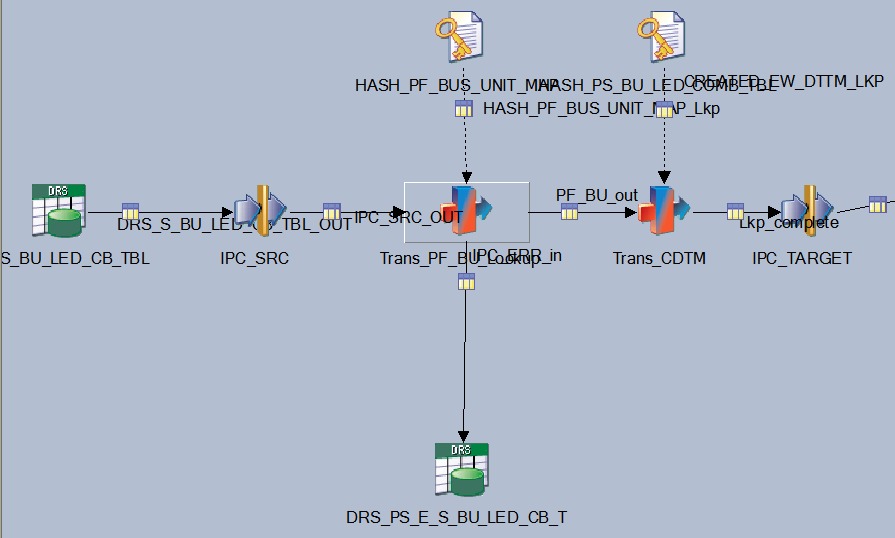
The following example shows a job that contains stages and links:
Image: Sample Job with Stages and Links - J_BASE_PS_BU_LED_COMB_TBL
This example illustrates the Sample Job with Stages and Links - J_BASE_PS_BU_LED_COMB_TBL.
A stage typically has at least one input or one output. However, some stages can have multiple inputs and output to more than one stage.
Different types of job have different stage types. The stages that are available in the DataStage Designer are dependent on the job type that is currently open in the DataStage Designer.
Adding Stages
To add a stage to a job, click a stage type in the palette, and click in the Diagram window.
The stages are located as follows:
Database stages are located in the Database palette group.
File stages are located in the File palette group.
Processing stages are located in the Processing group.
This group includes the Transformer and Pivot stages used in PeopleSoft-delivered jobs.
If the link is red, then the link is broken. Start and end the drag motion in the center of each stage to ensure that you have linked the stages correctly.
Adding Links
To add a link between stages, you click the Link object in the General palette group, and then click and drag the cursor from one stage to another.
Another option is to right-click on one stage and drag the link to another stage.
By default, new links are named. However, we recommend that you rename all of your links to reflect their purpose and avoid confusion when you are editing transformers and stage properties.