Using Database and File Stages
Database stages represent data sources or data targets.
DataStage provides three types of stages:
Server Job Database Stages
Server Job File Stages
Dynamic Relational Stages
Processing Stages
Each stage has a set of predefined and editable properties.
Server Job Database Stages
The following are some of the delivered server job database stages:
ODBC
UniVerse
UniData
Oracle
Sybase
Server Job File Stages
The delivered server job file stages are:
Sequential file
Hashed file
Complex flat file
Folder
Dynamic Relational Stages
Dynamic Relational Stages (DRS):
Read data from any DataStage stage.
Read data from any supported relational database.
Write to any DataStage stage.
Write to any supported relational database.
PeopleSoft-delivered ETL jobs use the DRS stage for all database sources or targets. This is represented in the Database group as "Dynamic RDBMS." When you create jobs, it is advisable to use the DRS stage rather than a specific type such as DB2 because a DRS will dynamically handle all of PeopleSoft supported database platforms.
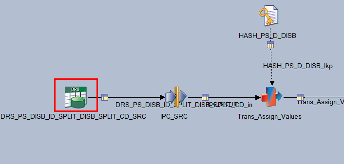
The following example shows a DRS database stage in a delivered Campus Solutions Warehouse job:
Image: DRS Stage
This example illustrates the DRS Stage.
A DRS database stage supports the following relational databases:
DB2/UDB
Informix
Microsoft SQL Server
Oracle
Sybase
A DRS database stage also supports any generic ODBC interface.
Editing the DRS Stage
You edit the DRS properties using the DRS stage window.
Double-click the DRS stage to open the DRS stage window.
The DRS stage window contains two main tabs: the Stage tab and the Output tab:
Image: DRS Stage Window
This example illustrates the DRS Stage Window.
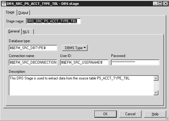
The Stage tab contains two tabs: the General tab and the NLS tab. In the General tab, you define the source database type, database or connection name, user ID, and password used in that connection. The previous example uses environment variables to define the values of these fields. If environment variables or job parameters were not used in the DRS stage, you define the actual values in these fields.
Entering Information in the Output Window
The Output tab contains General, Columns, Selection, and SQL tabs:
Image: DRS Stage Output Window
This example illustrates the DRS Stage Output Window.
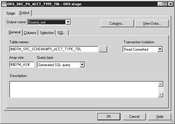
In this example, the table name listed is the source of the data that this stage uses.
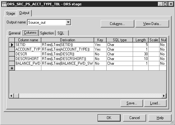
The Columns window shown below enables you to select which columns of data you want to pass through to the next stage. When you click the Load button, the system queries the source table and populates the grid with all the column names and properties. You can then delete rows that are not needed.
The following example shows the Columns window:
Image: DRS Stage Output Window - Columns Tab
This example illustrates the DRS Stage Output Window - Columns Tab.
The Selection window enables you to enter a Structured Query Language (SQL) WHERE clause that specifies conditions when fetching data from tables.
Image: DRS Stage Output Window - Selection Tab
This example illustrates the DRS Stage Output Window - Selection Tab.
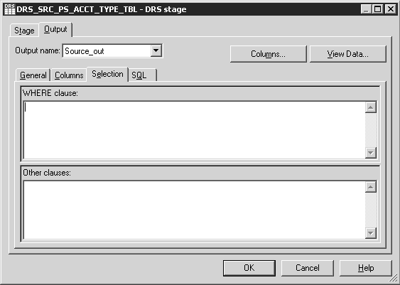
Entering a WHERE clause in the Selection window is optional.
The following shows the SQL tab of a DRS stage:
Image: DRS Stage Output Window - SQL Tab
This example illustrates the DRS Stage Output Window - SQL Tab.
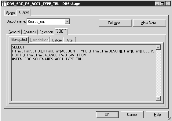
The SQL tab contains the SQL statement used for the current stage.
|
Window Element |
Usage |
|---|---|
|
Generated |
Shows the SQL SELECT statement that is automatically generated by this stage. It is read-only. |
|
Before |
Enter optional SQL statements executed before the stage processes job data rows. This does not appear in every plug-in. |
|
After |
Enter optional SQL statements executed after the stage processes job data rows This does not appear in every plug-in. |
Note: You can define SQL in a DRS Stage.
Processing Stages
DataStage Processing Stages:
Reads the data from the source.
Processes, transforms, or converts the data read from the source.
Writes the processed data to the target.
Processing Stage Types
This table describes the different types of Processing Stages:
|
Processing Stage |
Description |
|---|---|
|
Transformer |
Transformer stages perform transformations and conversions on extracted data. |
|
Aggregator |
Aggregator stages group data from a single input link and perform aggregation functions such as COUNT, SUM, AVERAGE, FIRST, LAST, MIN, and MAX. |
|
FTP |
FTP Stages transfer files to other machines. |
|
Link Collector |
Link Collectors collect partitioned data and pieces them together. |
|
Interprocess |
An InterProcess (IPC) stage is a passive stage which provides a communication channel between WebSphere DataStage processes running simultaneously in the same job. It allows you to design jobs that run on SMP systems with great performance benefits. |
|
Pivot |
Pivot, an active stage, maps sets of columns in an input table to a single column in an output table. |
|
Sort |
Sort Stages allow you to perform Sort operations. |
Transformer Stages
Transformer stages enable you to:
Add, delete, or move columns.
Apply expressions to data.
Use lookups to validate data.
Filter data using constraints.
Edit column metadata and derivations.
Define local stage variables, and before-stage and after-stage subroutines.
Specify the order in which the links are processed.
Pass data on to either another transformer stage, or to a target stage.
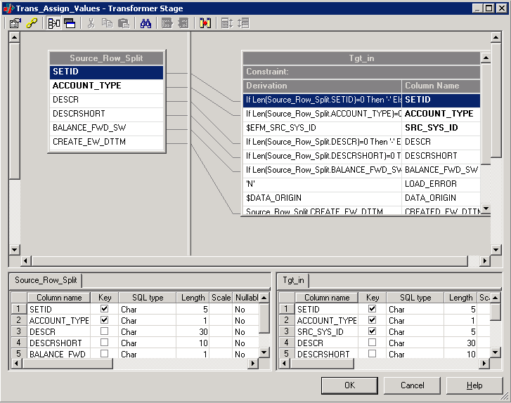
The following is an example of a delivered Transformer Stage (Trans_Assign_Values Stage):
Image: Trans_Assign_Values Transformer Stage
This example illustrates the Trans_Assign_Values Transformer Stage.
Creating Transformer Stages
You create a transformer stage by opening the Processing group in the palette, selecting the Transformer stage, and clicking in the Diagram window. After creating links to connect the transformer to a minimum of two other stages (the input and output stages), double-click the Transformer icon to open the Transformer window.
In the example above, two boxes are shown in the upper area of the window representing two links. Transformer stages can have any number of links with a minimum of two. Hence, there could be any number of boxes in the upper area of the window. Labeling your links appropriately makes it easier for you to work in the Transformer Stage window.
The lines that connect the links define how the data flows between them. When you first create a new transformer, you link it to other stages, and then open it for editing. There will not be any lines connecting the Link boxes. These connections can be created manually by clicking and dragging from a particular column of one link to a column in another link, or by selecting the Column Auto-Match button on the toolbar.
Using the Transformer Stage Toolbar
The following buttons appear on the Transformer Stage toolbar:
Image: Transformer Stage Toolbar
This example illustrates the Transformer Stage Toolbar.

This table describes the buttons provided with the Transformer Stage toolbar
|
Transformer Toolbar Button |
Usage |
|---|---|
|
Stage Properties |
Define stage inputs and outputs when you link the transformer with other stages. Specify before-stage and after-stage subroutines (optional). Define stage variables. Define order in which input and output links are processed if there is more than one input or output link. |
|
Constraints |
Enter a condition that filters incoming data, allowing only the rows that meet the constraint criteria to flow to the next stage. |
|
Show All or Selected Relations |
If you have more than two links in the transformer, you can select one link and click this button to hide all connection lines except for those on the selected link. With only two links present, clicking this button hides or displays all connections. |
|
Show/Hide Stage Variables |
Show or hide a box that displays local stage variables that can be assigned values in expressions, or be used in expressions. |
|
Cut, Copy, Paste, Find/Replace |
These are standard Windows buttons. |
|
Load Column Definition |
Load a table definition from the repository, or import a new one from a database. |
|
Save Column Definition |
Save a column definition in the repository so that it can be used in other stages and jobs. |
|
Column Auto-Match |
Automatically sets columns on an output link to be derived from matching columns on an input link. You can then go back and edit individual output link columns where you want a different derivation. |
|
Input Link Execution Order |
Order the reference links. The primary data link is always processed first. |
|
Output Link Execution Order |
Order all output links. |