| StorageTek Virtual Library Extension Planning Guide E41530-04 |
|


 Previous |
 Next |
Oracle's StorageTek Virtual Library Extension (VLE) is back-end disk storage for VTSS. VLE provides:
An additional storage tier in the VSM solution. VTVs can now migrate from VTSS to VLE to provide fast access to recent data. Additionally, VTVs can transition from VLE storage to tape media (MVCs) for long term archive. You can control how VTVs are migrated and archived through the existing HSC Management and Storage Classes, providing full backward compatibility with previous configurations.
Back-end disk storage shared between multiple VTSS systems ensuring high-availability access to data.
|
Note: For VLE 1.1 and above, a ”VLE” is a collection of nodes interconnected with a private network. |
To VTCS, a VLE looks like a tape library except that the VTVs are stored in Virtual Multi-Volume Cartridges (VMVCs) on disk. With VLE, you can configure either a VLE and tape or a VLE only (for example, with Tapeless VSM configurations) back-end VTV storage solution. A VTSS can migrate VTVs to and recall them from a VLE, just as is done with a real tape library.
|
Caution:
|
The VLE solution consists of:
Virtual Tape Storage Subsystem (VTSS) hardware and microcode
Virtual Tape Control Subsystem (VTCS) software and Storage Management Component (SMC)
VLE hardware and software
The VLE, which is a factory-assembled unit in a Sun Rack II Model 1242, consists of the following hardware:
A server built on a Sun Server X2-4 platform.
Four 1GigE ports for a combination of SMC UUI connections and service connections.
A service (ILOM) port.
Four Quad-port 1GigE cards, which provide 16 Ethernet ports for data transfer.
One or more Oracle Storage Drive Enclosure DE2-24Cs (DE2-24C) that contain disk (HDDs) in a ZFS RAID array, scalable in effective capacities starting at 200TB for a single JBOD VLE (assuming a 4 to 1 compression ratio when the data is migrated to the VLE).
Two dual-port 10GigE Network Adapter (NIC) cards per server, which are required for the internal network connections for VLEs with 2 or more nodes (or, with the Oracle switch, for 3 or more nodes).
A DVD drive.
The VLE software consists of:
Oracle Solaris 11 Operating System.
ZFS file system and MySQL database.
The VLE application software.
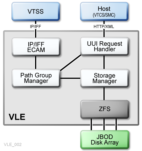
Figure 1-1 shows the VLE subsystem architecture.
As Figure 1-1 shows, the VLE application software consists of:
HTTP/XML is the data protocol for host to VLE communications.
The Universal User Interface (UUI) Request Handler, which processes UUI requests from and produces responses to Storage Management Component (SMC) and Virtual Tape Control Software (VTCS). The UUI Request Handler determines which VLE components are used to service a request.
UUI Request Handler calls:
The PathGroup Manager to schedule VTV migrates and recalls. The PathGroup Manager manages all Path Groups, where each Path Group manages a single VTV data transfer between the VTSS and the VLE.
The Storage Manager to schedule all report generation.
The VLE Storage Manager component manages the VMVC/VTV data and meta data on the VLE. The VLE Storage Manager stores VTV data on and retrieves it from the ZFS on the JBOD array.
TCP/IP/IFF is the data protocol for host to VLE communications, where the IP/IFF/ECAM component handles communications between the VTSS and the VLE.
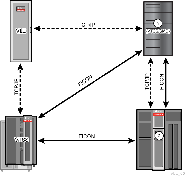
Figure 1-2 shows a single node VLE configuration.
As Figure 1-2 shows (where 1 is the MVS host and 2 is the library):
Multiple TCP/IP connections (between the VTSS's IP ports and the VLE's IP ports) are supported as follows:
A single VLE can connect up to 8 VTSSs, so VTSSs can share VLEs.
A single VTSS can connect to up to 4 VLEs to increase buffer space for heavy workloads.
A single VTSS can be attached to:
Only RTDs
Only other VTSSs (clustered)
Only VLEs
Any combination of the above.
TCP/IP is the only supported protocol for connections between the VLE and the VTSS and for connections between the VLE and hosts running SMC and VTCS.
Multi-node VLE systems enable massive scaling of the VLE storage system. You can construct multi-node systems that can consist of one to 64 nodes, with multiple nodes interconnected by a private network. A multi-node VLE appears to SMC/VTCS as a single VLE. For Version 1.4, the VLE now ships with 4Tb JBODs. A single VLE, therefore, can scale between 200 TB (for a one JBOD system) and 100 PB (for a fully populated 64-node VLE).
|
Note: These are effective capacities, assuming 4:1 compression. Also note that VLE is architected for up to 64 nodes, but has only been validated for up to 7 nodes. |
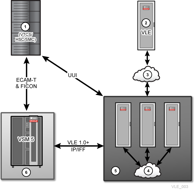
Figure 1-3 shows a VLE multi-node complex, where the nodes are cross connected into a dedicated 10GE switch so that each node can access any other node in the complex, where:
1 - MVS Host
2 - Remote VLE
3 - Public Network
4 - Private Network
5 - VLE Multi-Node Grid
6 - Virtual Tape Storage System
The VLE storage system can manage data transfers independently of the VTSS, which frees VTSS resources for front-end (host) workload, which improves the overall VTSS through-put. For example:
If your migration policies specify that there should be two VLE copies of a VTV (either in the same or separate VLEs), then the first migrate to a VLE will cause data to be transferred from the VTSS and all subsequent VLE migrates for the VTV may be achieved through a VLE to a VLE copy. This reduces the VTSS cycle times required to migrate all copies of a VTV.
If your environment runs:
VLE 1.2 or above, and
VTCS 7.1 (with the supporting PTFs) or VTCS 7.2
Then you can use VTCS to define more VLE devices than there are VTSS to VLE paths through the CONFIG STORMNGR VLEDEV parameter. If you use this addressing scheme, then the VTSS resources used to migrate all the VTV copies to VLE are reduced even further because the path from the VTSS to the target VLE is only reserved when the data transfer is direct from the VTSS to the VLE. For all VLE VRTD actions, a path from the VTSS is only reserved when VTSS data transfer is required.
The encryption feature enables encryption of VMVCs written to the VLE system. Encryption is enabled on a per node basis, through an encryption key stored on the node, backed up on a USB device. Encryption is entirely managed through the VLE GUI; the host software has no knowledge of encryption, as the VLE deencrypts VTVs that are recalled to the VTSS.
Deduplication eliminates redundant data in a VLE complex. Deduplication, which is controlled by the STORCLAS statement DEDUP parameter, increases the effective VLE capacity and is performed by the VLE before the VTV is written to a VMVC .
To assess deduplication results, enable deduplication, monitor the results with the SCRPT report, and fine tune deduplication as necessary. The SCRPT report provides the approximate ”reduction ratio” for the deduplicated data, which is uncompressed Gb divided by used Gb. The Reduction Ratio, therefore, includes both VTSS compression and VLE deduplication. A larger reduction ratio indicates more effective compression and deduplication.
For example, the VTSS receives 16 Mb of data, compresses it to 4Mb, and writes the compressed data to a VTV. VLE subsequently deduplicates the VTV to 2Mb and writes it to a VMVC. Thus, the reduction ratio is 16Mb divided by 2Mb or 8.0:1.
Early Time To First Byte (ETTFB), also known as the concurrent tape recall/mount feature, allows the VTSS to use a VTD to read data as it being recalled from VLE:
ETTFB is set globally through CONFIG GLOBAL FASTRECL.
If CONFIG GLOBAL FASTRECL=YES, you can disable ETTFB on per VTSS basis through CONFIG VTSS NOERLYMNT.
CONFIG GLOBAL and CONFIG VTSS apply to both ETTFB for RTDs and ETTFB for VLE.
Frame Size Control specifies the use of Jumbo frames on each copy link:
If your TCP/IP network supports Jumbo Frames, enabling this option can improve network performance.
You enable Jumbo Frames by selecting the Jumbo Frames check box on the Port Card Configuration Tab. Selecting this box sets the MTU (Maximum Transmission Unit) value to 9000 for the port.
|
 Copyright © 2013, 2014, Oracle and/or its affiliates. All rights reserved. Legal Notices |
|