Remove and Install Individual Fans

The individual fan is a user-serviceable, hot-pluggable component. There are 15 individual fans in the Net- Net 6300. If the Acme Packet 6300/6350 experiences a fan malfunction, you must remove the existing fan and replace it with a functional one.

The hot-pluggable fan removal and replacement procedures require that you have a replacement fan on hand. In order to maintain system operations you must be able to remove the malfunctioning fan and quickly replace it with a functioning one to prevent the system from overheating.

The Acme Packet 6300/6350 air filter is built into the front bezel and is not a FRU.

Note:

An over temperature condition can stop packet processing.

If you do not have a replacement fan nearby, always shut down the system and disconnect the power before removing the malfunctioning fan to replace it at a later time.

When removing and replacing a fan, remember to first ground yourself using appropriate ESD grounding equipment such as a wrist or heel strap.

To remove a fan:
  1. Press two fingers against the left end of the plastic fan bezel and pull it directly toward you. There are 4 posts that hold the bezel in place.
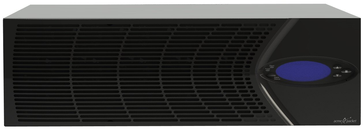
    This picture shows the front of the chassis.

    Acme Packet 6300/6350 With Attached Bezel

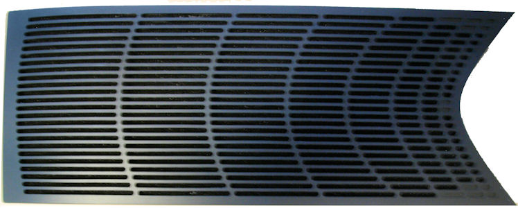
    This picture shows the front bezel.

    Front Bezel

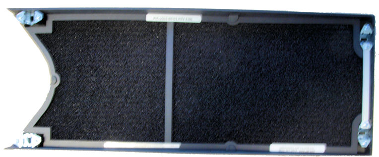
  2. The back side of the bezel holds the fan filter and is outfitted with four receptacles to attach to four chassis posts that hold the bezel in place on the chassis
    This picture shows the back side of the front bezel.

    Back Side of the Front Bezel

  3. Set the fan bezel aside.
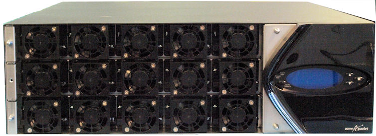
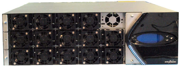
    This picture shows the front of the chassis with the bezel removed.

    Acme Packet 6300/6350 Fans

    Note:

    The 15 individual Fans are in the front of the chassis.

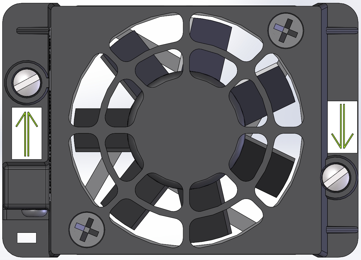
    There are two flat head screws on either side of the Fan, that hold each Fan in place.

  4. Using a flathead screwdriver, unscrew the two flat head captive screws at each side of the individual fan you are replacing.
    This diagram shows the captive screws on an indivicual fan.

    Captive Screws

  5. Pull the individual fan you just unscrewed directly toward you and out of the chassis. Move the fan to an ESD safe location.
    This picture shows the chassis with the bezel removed and one fan removed.

    Removed Fan