C In-Rack Cabling Tables for Oracle Big Data Appliance X4-2 and X3-2
The tables in this appendix show the in-rack cable connections for Oracle Big Data Appliance X4-2 and Oracle Big Data Appliance X3-2 racks. This appendix contains the following sections:
C.2 Oracle Big Data Appliance Rack Layout
The following figures show the front and rear layouts for three configurations of Oracle Big Data Appliance X4-2 and X3-2: full rack, starter rack, and starter rack with one in-rack expansion kit.
Figure C-1 shows the layout of a full rack for Oracle Big Data Appliance X4-2 or Oracle Big Data Appliance X3-2.
Figure C-1 Oracle Big Data Appliance X4-2 Full Rack Layout
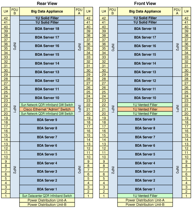
Description of "Figure C-1 Oracle Big Data Appliance X4-2 Full Rack Layout"
Figure C-2 shows the layout of a starter rack for Oracle Big Data Appliance X4-2 or Oracle Big Data Appliance X3-2.
Figure C-2 Oracle Big Data Appliance X4-2 Starter Rack Layout
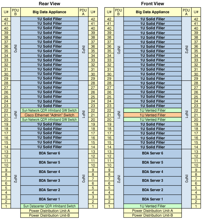
Description of "Figure C-2 Oracle Big Data Appliance X4-2 Starter Rack Layout"
Figure C-3 shows the layout of an Oracle Big Data Appliance X4-2 or Oracle Big Data Appliance X3-2 starter rack with one in-rack expansion kit.
Figure C-3 Oracle Big Data Appliance X4-2 Starter Rack With In-Rack Expansion
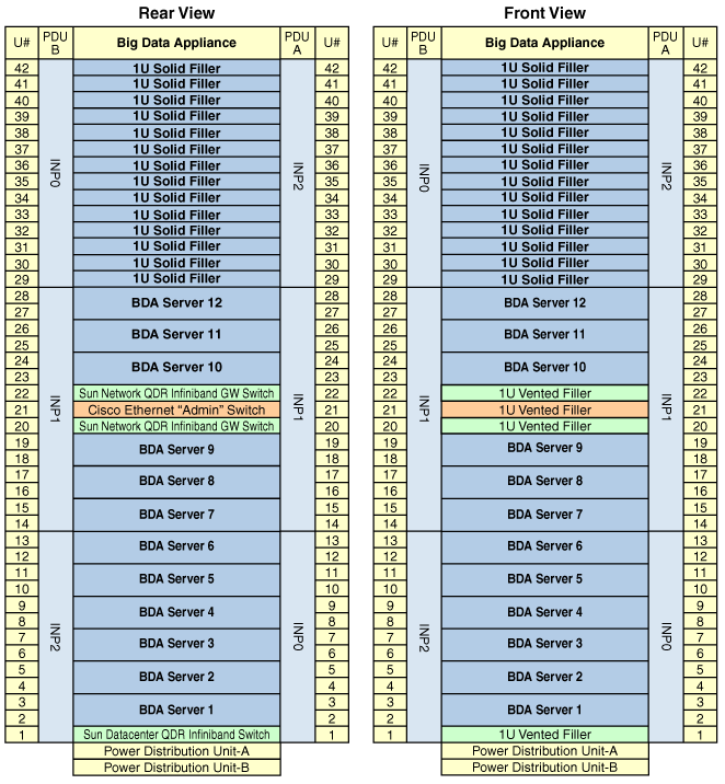
Description of "Figure C-3 Oracle Big Data Appliance X4-2 Starter Rack With In-Rack Expansion"
C.3 Administrative Gigabit Ethernet Cable Connections
Table C-1 shows the cable connections for the administrative Gigabit Ethernet network (Net 0). The Ethernet switch is located in rack unit 21. The cables are 10 feet long and black.
Table C-1 Administrative Gigabit Ethernet Cabling
| From Rack UnitFoot 1 | Component | To Ethernet Port |
|---|---|---|
|
U39 |
Server 18 |
1 |
|
U37 |
Server 17 |
3 |
|
U35 |
Server 16 |
5 |
|
U33 |
Server 15 |
7 |
|
U31 |
Server 14 |
9 |
|
U29 |
Server 13 |
11 |
|
U27 |
Server 12 |
13 |
|
U25 |
Server 11 |
17 |
|
U23 |
Server 10 |
21 |
|
U22 |
NM2-IB Switch |
45 |
|
U20 |
NM2-IB Switch |
46 |
|
U18 |
Server 9 |
25 |
|
U16 |
Server 8 |
29 |
|
U14 |
Server 7 |
31 |
|
U12 |
Server 6 |
33 |
|
U10 |
Server 5 |
35 |
|
U8 |
Server 4 |
37 |
|
U6 |
Server 3 |
39 |
|
U4 |
Server 2 |
41 |
|
U2 |
Server 1 |
43 |
|
U1 |
NM2-IB Switch |
47 |
Footnote 1 Un is the unit location in the rack, where n is the number.
C.4 Oracle Integrated Lights Out Manager Cable Connections
Table C-2 shows the cable connections from the servers to the Oracle ILOM switch. The Oracle ILOM ports on the servers are labeled Net Mgt and connect to the Cisco Ethernet switch located in rack unit 21.
| From Rack UnitFoot 1 | Component | Ethernet Port | Cable Length | Cable Color |
|---|---|---|---|---|
|
U39 |
Server 18 |
2 |
10 feet |
Red |
|
U37 |
Server 17 |
4 |
10 feet |
Red |
|
U35 |
Server 16 |
6 |
10 feet |
Red |
|
U33 |
Server 15 |
8 |
10 feet |
Red |
|
U31 |
Server 14 |
10 |
10 feet |
Red |
|
U29 |
Server 13 |
12 |
10 feet |
Red |
|
U27 |
Server 12 |
14 |
10 feet |
Red |
|
U25 |
Server 11 |
18 |
10 feet |
Red |
|
U23 |
Server 10 |
22 |
10 feet |
Red |
|
U18 |
Server 9 |
26 |
10 feet |
Red |
|
U16 |
Server 8 |
30 |
10 feet |
Red |
|
U14 |
Server 7 |
32 |
10 feet |
Red |
|
U12 |
Server 6 |
34 |
10 feet |
Red |
|
U10 |
Server 5 |
36 |
10 feet |
Red |
|
U8 |
Server 4 |
38 |
10 feet |
Red |
|
U6 |
Server 3 |
40 |
10 feet |
Red |
|
U4 |
Server 2 |
42 |
10 feet |
Red |
|
U2 |
Server 1 |
44 |
10 feet |
Red |
|
PDU-A |
PDU-A |
15 |
1 meter |
White |
|
PDU-B |
PDU-B |
20 |
1 meter |
White |
|
Not applicable |
Service |
48 |
10 feet |
Blue |
Footnote 1 Un is the unit location in the rack, where n is the number.
C.5 Single-Phase Power Distribution Unit Cable Connections
Table C-3 shows the connections for single-phase cabling from each power distribution unit (PDU) to the power supplies in the rack. The cables terminate at PDU-A on the left and are routed to the right to enter the cable management arm (CMA). The cables are bundled in groups of four.
Table C-3 Single-Phase PDU Cabling
| Rack UnitFoot 1 | PDU-A/PS-00 | PDU-B/PS-01 | Cable Length |
|---|---|---|---|
|
U39 |
G5-6 |
G0-0 |
2 meters |
|
U37 |
G5-3 |
G0-3 |
2 meters |
|
U35 |
G5-0 |
G0-6 |
2 meters |
|
U33 |
G4-6 |
G1-0 |
2 meters |
|
U31 |
G4-4 |
G1-2 |
2 meters |
|
U29 |
G4-2 |
G1-4 |
2 meters |
|
U27 |
G3-6 |
G2-0 |
2 meters |
|
U25 |
G3-5 |
G2-1 |
2 meters |
|
U23 |
G3-3 |
G2-3 |
2 meters |
|
U24 |
G3-1 |
G2-5 |
2 meters |
|
U23 |
Not applicable |
G3-0 |
included |
|
U22 |
G2-5 |
G3-1 |
1 meter |
|
U21 |
G3-0 |
G2-6 |
2 meters |
|
U20 |
G2-4 |
G3-2 |
2 meters |
|
U18 |
G2-2 |
G3-4 |
2 meters |
|
U16 |
G1-6 |
G4-0 |
2 meters |
|
U14 |
G2-0 |
G3-6 |
2 meters |
|
U12 |
G1-4 |
G4-2 |
2 meters |
|
U10 |
G1-2 |
G4-4 |
2 meters |
|
U8 |
G1-0 |
G4-6 |
2 meters |
|
U6 |
G0-6 |
G5-0 |
2 meters |
|
U4 |
G0-4 |
G5-2 |
2 meters |
|
U2 |
G0-2 |
G5-4 |
2 meters |
|
U1 |
G0-0 |
G5-6 |
2 meters |
Footnote 1 Un is the unit location in the rack, where n is the number.
C.6 Three-Phase Power Distribution Unit Cable Connections
Table C-4 describes three-phase cabling from each power distribution unit (PDU) to the power supplies in the rack. The cables are terminated to PDU-A on the left, are routed to the right to enter the cable management arm (CMA), and are bundled in groups of four.
Table C-4 Three-Phase PDU Cabling
| Rack UnitFoot 1 | PDU-A/PS-00 | PDU-B/PS-01 | Cable Length |
|---|---|---|---|
|
U39 |
G5-6 |
G2-0 |
2 meters |
|
U37 |
G5-3 |
G2-3 |
2 meters |
|
U35 |
G5-0 |
G2-6 |
2 meters |
|
U33 |
G4-6 |
G1-0 |
2 meters |
|
U31 |
G4-4 |
G1-2 |
2 meters |
|
U29 |
G4-2 |
G1-4 |
2 meters |
|
U27 |
G3-6 |
G0-0 |
2 meters |
|
U25 |
G3-5 |
G0-1 |
2 meters |
|
U23 |
G3-3 |
G0-3 |
2 meters |
|
U24 |
G3-1 |
G0-5 |
2 meters |
|
U23 |
Not applicable |
G5-0 |
Included |
|
U22 |
G2-5 |
G5-1 |
1 meter |
|
U21 |
G3-0 |
G0-6 |
2 meters |
|
U20 |
G2-4 |
G5-2 |
2 meters |
|
U18 |
G2-2 |
G5-4 |
2 meters |
|
U16 |
G1-6 |
G4-0 |
2 meters |
|
U14 |
G2-0 |
G5-6 |
2 meters |
|
U12 |
G1-4 |
G4-2 |
2 meters |
|
U10 |
G1-2 |
G4-4 |
2 meters |
|
U8 |
G1-0 |
G4-6 |
2 meters |
|
U6 |
G0-6 |
G3-0 |
2 meters |
|
U4 |
G0-4 |
G3-2 |
2 meters |
|
U2 |
G0-2 |
G3-4 |
2 meters |
|
U1 |
G0-0 |
G3-6 |
2 meters |
Footnote 1 Un is the unit location in the rack, where n is the number.
C.7 In-Rack InfiniBand Switch-to-Switch Cable Connections
Table C-5 lists the location, ports, and cables for the InfiniBand connections from switch to switch.
Table C-5 InfiniBand Switch-to-Switch Cabling
| From InfiniBand Switch Rack UnitFoot 1 | Port | To InfiniBand Switch Rack UnitFootref 1 | Port | Cable Length | Description |
|---|---|---|---|---|---|
|
U20 |
9B |
U22 |
9A |
2 meters |
Leaf to leaf |
|
U20 |
10B |
U22 |
10A |
2 meters |
Leaf to leaf |
|
U20 |
11B |
U22 |
11A |
2 meters |
Leaf to leaf |
|
U20 |
8A |
U22 |
8A |
2 meters |
Leaf to leaf |
|
U20 |
9A |
U22 |
9B |
2 meters |
Leaf to leaf |
|
U20 |
10A |
U22 |
10B |
2 meters |
Leaf to leaf |
|
U20 |
11A |
U22 |
11B |
2 meters |
Leaf to leaf |
|
U1 |
0B |
U20 |
8B |
3 meters |
Spine to leaf |
|
U1 |
1B |
U22 |
8B |
3 meters |
Spine to leaf |
Footnote 1 Un is the unit location in the rack, where n is the number.
Figure C-4 identifies the locations of the ports on a Sun Network QDR InfiniBand Gateway switch. Ports 5A, 5B, 6A, 6B, and 7A are available to connect to another device, such as Oracle Exalytics In-Memory Machine. Oracle recommends that you start with port 5A. Port 7B is reserved for future use by Oracle Big Data Appliance.
Figure C-4 Sun Network QDR InfiniBand Gateway Ports
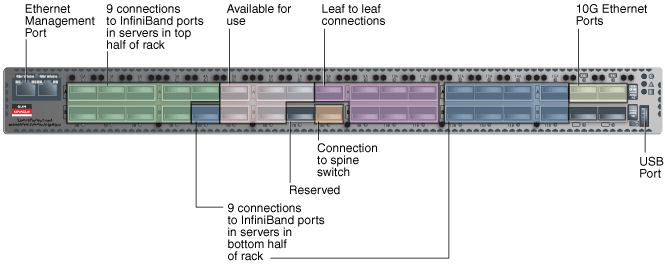
Description of "Figure C-4 Sun Network QDR InfiniBand Gateway Ports"
C.8 In-Rack InfiniBand Switch-to-Server Cable Connections
Table C-6 lists the location, ports, and cables for the InfiniBand connections from the leaf switches to the servers.
Table C-6 InfiniBand Switch-to-Server Cabling
| From InfiniBand Switch Rack UnitFoot 1 | Port | To Rack UnitFootref 1 | PortFoot 2 | Cable Length |
|---|---|---|---|---|
|
U22 |
0A |
U39 |
PCIe 3 P1 |
3 meters |
|
U22 |
0B |
U37 |
PCIe 3 P1 |
3 meters |
|
U22 |
1A |
U35 |
PCIe 3 P1 |
3 meters |
|
U22 |
1B |
U33 |
PCIe 3 P1 |
3 meters |
|
U22 |
2A |
U31 |
PCIe 3 P1 |
3 meters |
|
U22 |
2B |
U29 |
PCIe 3 P1 |
3 meters |
|
U22 |
3A |
U27 |
PCIe 3 P1 |
3 meters |
|
U22 |
3B |
U25 |
PCIe 3 P1 |
2 meters |
|
U22 |
4A |
U23 |
PCIe 3 P1 |
2 meters |
|
U20 |
0A |
U39 |
PCIe 3 P2 |
3 meters |
|
U20 |
0B |
U37 |
PCIe 3 P2 |
3 meters |
|
U20 |
1A |
U35 |
PCIe 3 P2 |
3 meters |
|
U20 |
1B |
U33 |
PCIe 3 P2 |
3 meters |
|
U20 |
2A |
U31 |
PCIe 3 P2 |
3 meters |
|
U20 |
2B |
U29 |
PCIe 3 P2 |
3 meters |
|
U20 |
3A |
U27 |
PCIe 3 P2 |
3 meters |
|
U20 |
3B |
U25 |
PCIe 3 P2 |
2 meters |
|
U20 |
4A |
U23 |
PCIe 3 P2 |
2 meters |
|
U20 |
4B |
U18 |
PCIe 3 P1 |
2 meters |
|
U20 |
12A |
U16 |
PCIe 3 P1 |
2 meters |
|
U20 |
12B |
U14 |
PCIe 3 P1 |
3 meters |
|
U20 |
13A |
U12 |
PCIe 3 P1 |
3 meters |
|
U20 |
13B |
U10 |
PCIe 3 P1 |
3 meters |
|
U20 |
14A |
U8 |
PCIe 3 P1 |
3 meters |
|
U20 |
14B |
U6 |
PCIe 3 P1 |
3 meters |
|
U20 |
15A |
U4 |
PCIe 3 P1 |
3 meters |
|
U20 |
15B |
U2 |
PCIe 3 P1 |
3 meters |
|
U22 |
4B |
U18 |
PCIe 3 P2 |
2 meters |
|
U22 |
12A |
U16 |
PCIe 3 P2 |
2 meters |
|
U22 |
12B |
U14 |
PCIe 3 P2 |
3 meters |
|
U22 |
13A |
U12 |
PCIe 3 P2 |
3 meters |
|
U22 |
13B |
U10 |
PCIe 3 P2 |
3 meters |
|
U22 |
14A |
U8 |
PCIe 3 P2 |
3 meters |
|
U22 |
14B |
U6 |
PCIe 3 P2 |
3 meters |
|
U22 |
15A |
U4 |
PCIe 3 P2 |
3 meters |
|
U22 |
15B |
U2 |
PCIe 3 P2 |
3 meters |
Footnote 1 Un is the unit location in the rack, where n is the number.
Footnote 2 Pn is the InfiniBand port, where n is the port number.