3 Understanding the Network Requirements
This chapter describes the network requirements for Oracle Big Data Appliance. This chapter contains these sections:
3.1 Overview of Network Requirements
Oracle Big Data Appliance includes 6, 12, or 18 servers and the equipment to connect the servers to your network. The network connections allow the servers to be administered remotely and allow clients to connect to them. Use the information in this chapter to configure the environment for Oracle Big Data Appliance.
Each server has the following network components and interfaces:
-
1 Dual-port 4X QDR (40 Gbps) InfiniBand Host Channel Adapter network interface card
-
1 Ethernet port for Oracle Integrated Lights Out Manager v3.1 for remote management (v3.0 for Sun Fire X4270 M2 servers)
-
4 10-Gigabit Ethernet ports (1-Gigabit Ethernet ports for Sun Fire X4270 M2)
3.1.1 Default Network Connections
The installation process automatically discovers whether each Sun Network QDR InfiniBand Gateway switch has at least one 10 GbE connection. If they all do, then two virtual network interface cards (VNICs) are configured for each server: one for each switch bonded as bondeth0 in active/passive failover mode. The VNICs are assigned automatically to the available 10 GbE connections in round-robin fashion. For example, if each switch has three available 10 GbE connections, then the VNIC on server 1 is assigned to 10 GbE port 1, server 2 to port 2, server 3 to port 3, server 4 to port 1, and so on.
All VNICs are assigned to the same default virtual local area network (VLAN). To assign different VLANs to different VNICs, you must delete the initial VNICs and manually create your own.
3.1.2 Minimum Requirements for the Networks
Additional configuration, such as defining multiple VLANs or enabling routing, may be required for the switch to operate properly in your environment. If additional configuration is needed, then your network administrator must perform the necessary configuration steps during installation of Oracle Big Data Appliance.
To deploy Oracle Big Data Appliance, ensure that your network meets the minimum requirements. Oracle Big Data Appliance uses three networks. Each network must be on a distinct and separate subnet from the others. These are the network descriptions:
-
Administrative network: This 1 gigabit Ethernet (GbE) network connects to your existing administrative network and is used to administer all components of Oracle Big Data Appliance. It connects the servers, Oracle ILOM, and InfiniBand switches connected to the Ethernet switch in the rack.
There are two uplinks to the administrative network:
-
From the Ethernet switch in the rack
-
From the KVM switch in the rack (Sun Fire X4270 M2-based racks only)
Each server has two network interfaces for administration. One provides administrative access to the operating system through the eth0 Ethernet interface, and the other provides access to the Integrated Lights Out Manager through the Oracle ILOM Ethernet interface. Oracle Big Data Appliance is delivered with the eth0 and ILOM interfaces connected to the Ethernet switch on the rack. Do not use the eth0 interface on the servers for client network traffic. Cabling or configuration changes to these interfaces are not permitted.
Domain Name System (DNS) servers are not required on the administrative network, although Oracle Big Data Appliance uses them if they are available. At least one Network Time Protocol (NTP) server must also be available. The NTP server for the administrative network can be different from the NTP server for the client network.
All Oracle Big Data Appliance components on the administrative network must be on the same subnet; that is, the eth0 IP addresses for all servers, ILOMs, PDUs, InfiniBand switches, and the Cisco Ethernet switch must be on the same subnet.
-
-
Client access network: This 10 GbE network connects the servers though the gateway switches to your existing client network and is used for client access to the servers. Client applications access the software through this network by using the client network host names of the servers.
There are two Sun Network QDR InfiniBand Gateway switches in the rack. Each switch supports 1 to 8 connections for client access for a total of up to 16 client network connections. For failover, you must have at least one connection from each switch and scale up according to your requirements for loading data and providing client access.
At least one DNS server must be accessible on the client network. At least one NTP server must also be available. The NTP server for the client network can be different from the NTP server for the administrative network.
-
InfiniBand private network: This network connects the servers by using the InfiniBand switches on the rack and the bondib0 interface. This nonroutable network is fully contained within Oracle Big Data Appliance and any other Oracle engineered systems that are connected to it with InfiniBand cables. This network does not connect to your existing network. It is automatically configured during installation.
Note:
All networks must be on distinct and separate subnets from each other.3.1.3 Network Diagram
The servers are configured on the network as follows:
-
eth0: Provides access to the operating system using the administrative network. -
bondeth0: Provides access to the server using the client access network. -
ILOM: Provides access to Oracle Integrated Lights Out Manager (ILOM) using the administrative network.
Use the bda-preinstall-checkip.sh script to verify the readiness of the network environment before cabling Oracle Big Data Appliance to the existing network. See "Preparing the Network for Oracle Big Data Appliance."
Figure 3-1 shows the network diagram for Sun Server X4-2L and Sun Server X3-2L-based racks.
Figure 3-1 Network Diagram for Oracle Big Data Appliance X4-2
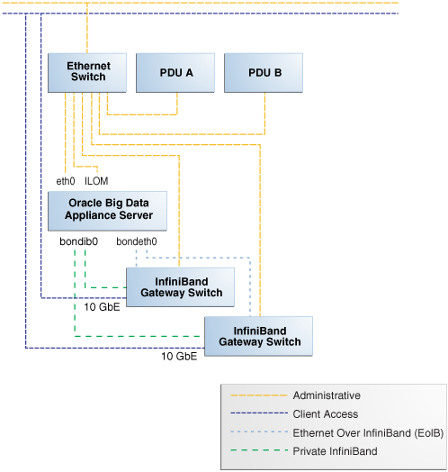
Description of "Figure 3-1 Network Diagram for Oracle Big Data Appliance X4-2"
Figure 3-2 shows the network diagram for a Sun Fire X4270 M2 -based rack, which includes a KVM.
Figure 3-2 Network Diagram for Oracle Big Data Appliance
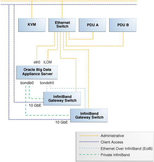
Description of "Figure 3-2 Network Diagram for Oracle Big Data Appliance"
3.2 Cabling the Client Network
Each of the two Sun Network QDR InfiniBand Gateway switches in Oracle Big Data Appliance has eight 10 GbE ports. The two switches enable you to create up to 16 10 GbE connections for each rack. You can determine how many connections to create based on the bandwidth needed for the client network. For proper functioning, at least one of the eight ports of each gateway switch must have an active connection to the site's 10 GbE network. Oracle recommends that the two switches have the same number of active 10 GbE connections, so that failover does not result in a loss of available client network bandwidth.
3.2.1 How the Servers Connect to the Gateway Switches
Physical Ethernet connections are created only between the site network and the gateway switches. The Oracle Big Data Appliance servers are connected only by InfiniBand to those switches. Each server has two InfiniBand connections, one to each gateway switch, in an active-passive backup mode; only the active InfiniBand connection is used for all InfiniBand traffic to that server. If that connection fails, it immediately fails over to the other connection.
Half of the Oracle Big Data Appliance servers have active connections to one gateway switch, and the other half have active connections to the other gateway switch. Inside Oracle Big Data Appliance, the client network traffic is transported over those InfiniBand connections using the Ethernet over InfiniBand (EoIB) protocol. As a result, each Oracle Big Data Appliance server has two virtual NICs (VNICs) that are bonded in the same active-passive backup mode. Each VNIC is assigned a specific port on the gateway switch. If a switch has only one 10 GbE connection, then all VNICs for that switch point to the same port. If a switch has multiple connections, then the VNICs are spread across those ports in round-robin fashion.
For example, if you create three 10 GbE uplinks from each gateway switch, then the client network traffic from the servers is handled by the switches as shown in the following table:
| Server Number | Active Link | Backup Link |
|---|---|---|
| 1 | GWFoot 1 Switch 1 Link 1 | GW Switch 2 Link 1 |
| 2 | GW Switch 1 Link 2 | GW Switch 2 Link 2 |
| 3 | GW Switch 1 Link 3 | GW Switch 2 Link 3 |
| 4 | GW Switch 1 Link 1 | GW Switch 2 Link 1 |
| ... | ... | ... |
| 17 | GW Switch 2 Link 2 | GW Switch 1 Link 2 |
| 18 | GW Switch 2 Link 3 | GW Switch 1 Link 3 |
Footnote 1 Sun Network QDR InfiniBand Gateway Switch
Depending on the number of 10 GbE connections, the client network traffic for multiple servers may be sent across the same physical 10 GbE connection. The maximum number of connections provides 160 gigabits per second (Gbps) of client network bandwidth to Oracle Big Data Appliance.
3.2.2 Using Splitter Cables for Connecting to the 40 Gbps Physical Ports
Although you can create up to eight 10 GbE connections for each gateway switch, its physical ports are 40 Gbps quad small form-factor pluggable (QSFP) ports. Each gateway switch has two of these physical ports reserved for 10 GbE connectivity. The ports are equipped with QSFP transceivers that take an optical cable with an MTP/MPO connector. On the site network side are typically 10 Gbps ports with SFP+ transceivers that take LC connectors. For these connections, you can use splitter cables that have a single male MTP/MPO connector on one end and four pairs of LC connectors on the other end. Each 10 Gbps SFP+ transceiver takes a duplex LC connector for a total of four pairs. Thus, you can use a single splitter cable to create up to four 10 GbE connections. However, all four duplex LC connectors do not require a connection to the site network.
The splitter cables are not provided with Oracle Big Data Appliance and must be ordered separately from Oracle. They are available in lengths of 10, 20, and 50 meters. Oracle recommends that you order the SFP+ transceivers used at the site end of the 10 GbE network from the same manufacturer as the 10 GbE switch.
3.2.3 What About Data Centers Without a 10 GbE Infrastructure?
If your data center does not have a 10 GbE infrastructure, you can still connect Oracle Big Data Appliance to it by using an external switch that supports both 10 GbE (or 40 GbE) and 1 GbE. The Sun Network 10 GbE Switch 72p and numerous third-party switches provide this capability. You can connect the Sun Network QDR InfiniBand Gateway switches to a 10 GbE or 40 GbE port and connect the data center to a 1 GbE port in the external switch.
3.2.4 Guidelines for Connecting to the Gateway Switches
Oracle recommends that you follow these guidelines for making 10 GbE connections to the two gateway switches in Oracle Big Data Appliance:
-
Make the same number of 10 GbE connections to both gateway switches.
-
To make 1 to 4 10-GbE connections to each switch, use a single QSFP splitter cable to the 0A-ETH port of both switches.
-
To make 5 to 8 10-GbE connections to each switch, use two QSFP splitter cables to both 0A-ETH and 1A-ETH ports of both switches. Divide the connections as evenly as possible between the 2 splitter cables.
-
To make multiple 10 GbE connections to a single QSFP splitter cable, start with the lowest number port and work upward. For example, for two connections, use 0A-ETH1 and 0A-ETH2.
-
Make the10 GbE connections to exactly the same ports on both NM2-GW switches. If you make connections to 0A-ETH1 and 0A-ETH2 on one switch, then make connections only to 0A-ETH1 and 0A-ETH2 on the other switch.
3.2.5 Configuring Multiple Racks into a Single Hadoop Cluster
When multiple Oracle Big Data Appliance racks are connected to form a single Hadoop cluster, Oracle strongly recommends that you spread the 10 GbE connections across the switches in different racks. Every gateway switch in every rack must have at least one 10 GbE connection. Oracle does not support a configuration in which the 10 GbE connections to the switches in a single rack are used for all servers in all Oracle Big Data Appliance racks.
3.3 Factory Network Settings
This initial network configuration is set at the factory for Oracle Big Data Appliance:
-
Gateway: 192.168.1.254 in all devices as required
-
Subnet Mask: 255.255.255.0 in all devices as required
-
IP Address Range: 192.168.1.1 to 192.168.1.211
Table 3-1 lists the default IP addresses for Oracle Big Data Appliance.
Table 3-1 Default IP Addresses for Oracle Big Data Appliance
| Host | Administrative IP Addresses | Oracle ILOM IP Addresses | InfiniBand Bonded IP Addresses |
|---|---|---|---|
|
bda18Foot 1 |
|
|
|
|
bda17Footref 1 |
|
|
|
|
bda16Footref 1 |
|
|
|
|
bda15Footref 1 |
|
|
|
|
bda14Footref 1 |
|
|
|
|
bda13Footref 1 |
|
|
|
|
bda12Foot 2 |
|
|
|
|
bda11Footref 2 |
|
|
|
|
bda10Footref 2 |
|
|
|
|
bdasw-ib3 |
|
||
|
Cisco Switch |
|
||
|
bdasw-ib2 |
|
||
|
bda9Footref 2 |
|
|
|
|
bda8Footref 2 |
|
|
|
|
bda7Footref 2 |
|
|
|
|
bda6 |
|
|
|
|
bda5 |
|
|
|
|
bda4 |
|
|
|
|
bda3 |
|
|
|
|
bda2 |
|
|
|
|
bda1 |
|
|
|
|
bdasw-ib1 |
|
||
|
PDU A |
|
||
|
PDU B |
|
Footnote 1 Full racks only
Footnote 2 Full racks or starter racks with in-rack expansions only
3.4 Port Assignments for Oracle Big Data Appliance Software
Table 3-2 identifies the port numbers used by Oracle Big Data Appliance software.
Table 3-2 Oracle Big Data Appliance Port Numbers
| Port | Used by |
|---|---|
|
22 |
ssh |
|
80 |
yumrepos (only during installation) |
|
111 |
portmap |
|
162 |
|
|
443 |
Auto Service Request Manager (optional) |
|
668 |
rpc.statd |
|
3306 |
MySQL Database |
|
5000 |
Oracle NoSQL Database registration |
|
5001 |
Oracle NoSQL Database administration |
|
5010 to 5020 |
Oracle NoSQL Database processes |
|
6481 |
Auto Service Request Manager service tags listener (optional) |
|
8139 |
Puppet nodes |
|
8140 |
Puppet parent |
|
20910 |
Oracle Data Integrator agent |
|
30920 |
Automated Service Monitor (ASM) |
Table 3-3 lists the ports used by Cloudera's Distribution including Apache Hadoop version 4 (CDH4). For additional details about these port assignments, go to the Cloudera website at
| Port | Component | Service | Access |
|---|---|---|---|
|
0 |
MapReduce 1 |
TaskTracker |
Localhost |
|
1004 |
HDFS |
Secure DataNode |
External |
|
1006 |
HDFS |
Secure DataNode |
External |
|
1200 |
Sqoop 2 |
Sqoop 2 Server |
External |
|
1201 |
Sqoop 2 |
Sqoop 2 |
External |
|
2181 |
HBase |
HQuorumPeer |
|
|
2181 |
ZooKeeper |
Server |
External |
|
2888 |
HBase |
HQuorumPeer |
|
|
2888 |
ZooKeeper |
Server |
Internal |
|
3181 |
ZooKeeper |
Server |
Internal |
|
3888 |
HBase |
HQuorumPeer |
|
|
3888 |
ZooKeeper |
Server |
Internal |
|
4181 |
ZooKeeper |
Server |
Internal |
|
8002 |
Hue |
Beeswax Server |
Internal |
|
8003 |
Hue |
Beeswax Metastore |
Internal |
|
8019 |
ZooKeeper |
ZooKeeper Failover Controller |
Internal |
|
8020 |
HDFS |
NameNode |
External |
|
8021 |
MapReduce 1 |
JobTracker |
External |
|
8030 |
YARN |
ResourceManager |
|
|
8031 |
YARN |
ResourceManager |
|
|
8032 |
YARN |
ResourceManager |
|
|
8033 |
YARN |
ResourceManager |
|
|
8040 |
YARN |
NodeManager |
|
|
8041 |
YARN |
NodeManager |
|
|
8042 |
YARN |
NodeManager |
|
|
8080 |
HBase |
REST Service |
External |
|
8085 |
HBase |
REST UI |
External |
|
8088 |
YARN |
ResourceManager |
External |
|
8480 |
HDFS |
JournalNode |
Internal |
|
8485 |
HDFS |
JournalNode |
Internal |
|
8888 |
Hue |
Server |
External |
|
9010 |
ZooKeeper |
ZooKeeper JMX |
Internal |
|
9083 |
Hive |
Metastore |
External |
|
9090 |
HBase |
Thrift Server |
External |
|
9090 |
HBase |
Avro Server |
External |
|
9095 |
HBase |
Thrift Server |
External |
|
9290 |
MapReduce |
JobTracker Thrift Plug-in |
Internal |
|
10000 |
Hive |
HiveServer |
External |
|
10020 |
MapReduce |
Job History Server |
|
|
11000 |
Oozie |
Server |
External |
|
11001 |
Oozie |
Server |
Localhost |
|
16000 |
Sqoop |
Metastore |
External |
|
19888 |
YARN |
MapReduce JobHistory Server |
|
|
50010 |
HDFS |
DataNode |
External |
|
50020 |
HDFS |
DataNode |
External |
|
50030 |
MapReduce |
JobTracker |
External |
|
50060 |
MapReduce |
TaskTracker |
External |
|
50070 |
HDFS |
NameNode |
External |
|
50075 |
HDFS |
DataNode |
External |
|
50090 |
HDFS |
Secondary NameNode |
Internal |
|
50470 |
HDFS |
Secure NameNode |
External |
|
50495 |
HDFS |
Secure Secondary NameNode |
Internal |
|
60000 |
HBase |
Master |
External |
|
60010 |
HBase |
Master |
External |
|
60020 |
HBase |
RegionServer |
External |
|
60030 |
HBase |
RegionServer |
External |
3.5 Preparing the Network for Oracle Big Data Appliance
Oracle Big Data Appliance Configuration Generation Utility generates these files for you to use before installation:
-
bda-install-review.html: Lists the host names and custom IP addresses for Oracle Big Data Appliance. Verify that the information is correct, and add the host names and IP addresses to a name server on the network. You can view this file in a browser.
-
bda-preinstall-checkip.sh: Performs validation checks on network configuration values, including host names and IP addresses.
See "Generating the Configuration Files."
Run the bda-preinstall-checkip.sh script at these points in the installation process:
-
Before Oracle Big Data Appliance arrives at the site but after the network administrator has added the new names and IP addresses to the name server. This step ensures that the network configuration parameters are valid and the network is ready to accept Oracle Big Data Appliance connections.
-
After Oracle Big Data Appliance arrives but before it is connected to the network. This step ensures that the network has not changed and is still ready to accept Oracle Big Data Appliance connections.
Note:
Runningbda-preinstall-checkip.sh is a critical pre-installation step. Network errors can cause extensive delays in the installation procedure.To check the network for conflicts:
-
Copy the
bda-preinstall-checkip.shscript to any Linux system with a 10 GB Ethernet connection to the subnet on which Oracle Big Data Appliance will be deployed. -
Ensure that the script is executable:
chmod +x bda-preinstall-checkip.sh
-
Execute the script:
./bda-preinstall-checkip.sh
-
If the script identifies errors, open the
bda-checkip.outfile for details. It contains information about every test the script performed. The output file is created in the same directory as the script. -
Resolve all reported errors before rerunning the script.
Example 3-1 shows success and error messages from the bda-preinstall-checkip.sh script.
Example 3-1 Output from bda-preinstall-checkip.sh
Big Data Appliance pre-installation network verification starting ...

Using name server 198.51.100.21 for all DNS lookups

Domain is example.com

Processing DNS name servers : SUCCESS
Processing NTP time servers : SUCCESS
Processing gateways : SUCCESS
Processing factory IP addresses : SUCCESS
Processing public node names (bondeth0) : SUCCESS
Processing private IP addresses (bondib0) : ERROR - see bda-checkip.out for details
Processing admin node names (eth0) : SUCCESS
Processing ILOM names : SUCCESS
Processing switch and PDU IP addresses : SUCCESS
Processing ASR hostname : SUCCESS

One or more checks report ERROR. Review bda-checkip.out for details