SAS cables establish the Backend SAS Interconnect of an Oracle FS System. SAS cables connect Drive Enclosures to Drive Enclosures and the Controller SAS HBA ports to the Drive Enclosure strings.
Usage Conventions for Cabling Drive Enclosure
The following usage conventions summarize how the ports are used when cabling
Drive Enclosures:
Controller 1 HBA ports 0 and ports 1 connect to the first Drive Enclosure (I/O module 0, port 0) in a string.
Controller 2 HBA ports 0 and ports 1 connect to the third Drive Enclosure (I/O module 1, port 0) in strings that support three or more Drive Enclosures.
Controller 2 HBA ports 0 and ports 1 connect to the second Drive Enclosure (I/O module 1, port 0) or to the first Drive Enclosure (I/O module 1, port 0) in strings that support less than three Drive Enclosures.
I/O module 0, port 1 connects to the second Drive Enclosure (I/O module 0, port 0) and to the third Drive Enclosure (I/O module 0, port 0) in a string.
I/O module 1, port 2 connects to the fourth Drive Enclosure (I/O module 1, port 0) and to the fifth Drive Enclosure (I/O module 1, port 0) in a string.
Note: The Oracle FS System supports three hops from the HBAs.
Drive Enclosure SAS Wiring Diagrams
The following wiring diagrams show the cabling of
Drive Enclosures for one string in a system. The same cabling pattern applies to all of the strings in a system.
Note: The following wiring diagrams show DE2-24P Drive Enclosures. Note the position of the SAS ports and the reverse orientation of the two I/O modules on the DE2-24P Drive Enclosures. Conversely, the two I/O modules on the DE2-24C Drive Enclosures have an identical orientation. Remember the orientation of the I/O modules and the location of the SAS ports as you cable the system.
The following figure illustrates the SAS cabling for one
Drive Enclosure string containing one
Drive Enclosure.
Figure 1 SAS wiring diagram for one string with one Drive Enclosure 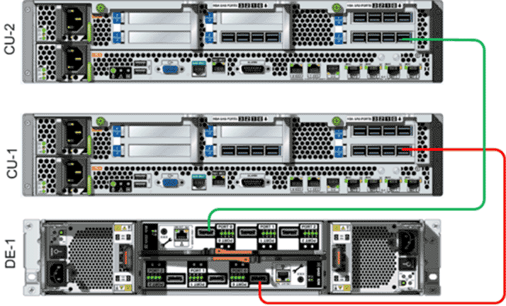
The following figure illustrates the SAS cabling in a system that is configured with one
Drive Enclosure string containing two
Drive Enclosures.
Figure 2 SAS wiring diagram for one string with two Drive Enclosures 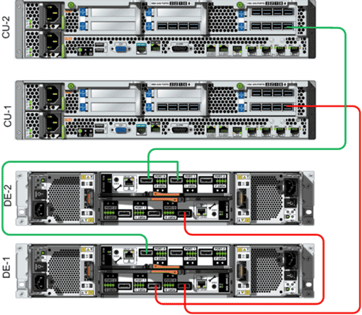
The following figure illustrates the SAS cabling in a system that is configured with one
Drive Enclosure string containing three
Drive Enclosures.
Figure 3 SAS wiring diagram for one string with three Drive Enclosures 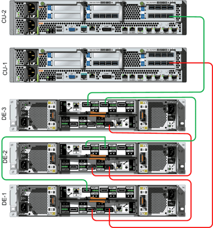
The following figure illustrates the SAS cabling in a system that is configured with one
Drive Enclosure string containing four
Drive Enclosures.
Figure 4 SAS wiring diagram for one string with four Drive Enclosures 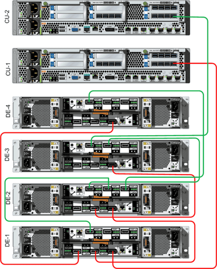
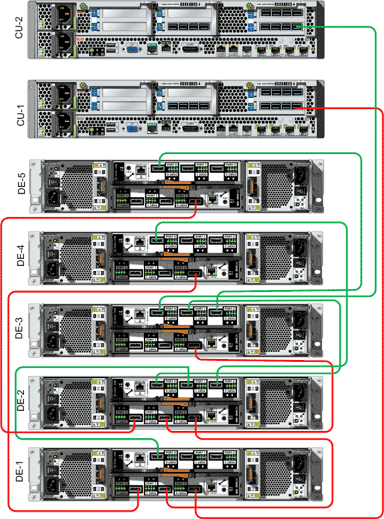
The following figure illustrates the SAS cabling in a system that is configured with one
Drive Enclosure string containing five
Drive Enclosures.
Figure 5 SAS wiring diagram for one string with five Drive Enclosures