Use the appropriate wiring diagram for your replication configuration to cable the Oracle MaxRep Replication Engine.
The wiring diagrams below represent the following Oracle MaxRep for SAN configurations:
-
Fibre Channel (FC) configuration
-
iSCSI configuration using RJ45 connectors
-
FC and iSCSI configuration using RJ45 connectors
-
iSCSI configuration using SFP or optical connectors
-
FC and iSCSI configuration using SFP or optical connectors
Figure 1: FC configuration
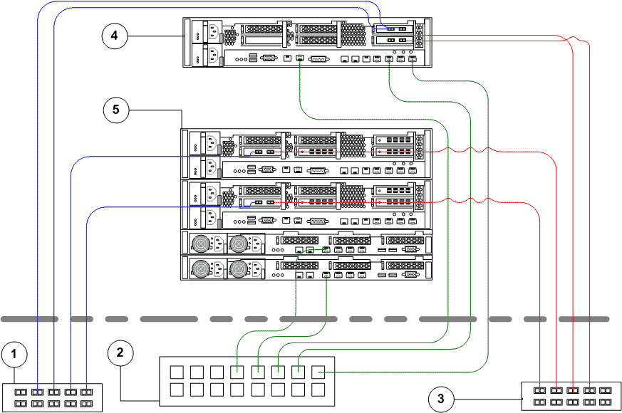
- Legend
-
1 SAN fabric switch A 2 Ethernet switch 3 SAN fabric switch B 4 Oracle MaxRep Replication Engine 5 Oracle FS System Controllers and Pilots (Drive Enclosures not shown)
The following figure provides information on the cable connections with iSCSI configuration using RJ45 connectors.
Figure 2: iSCSI configuration using RJ45 connectors
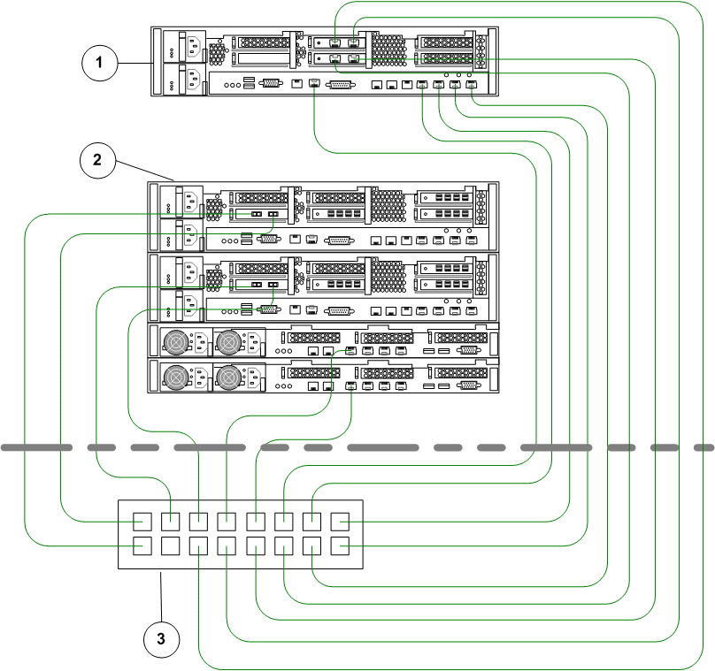
- Legend
-
1 Oracle MaxRep Replication Engine 2 Oracle FS System Controllers and Pilots ( Drive Enclosures not shown) 3 Ethernet switch
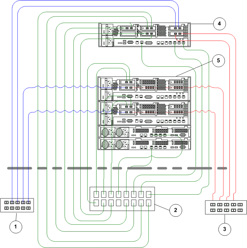
The following figure provides information on the cable connections for a FC and iSCSI configuration using RJ45 connectors.
Figure 3: FC and iSCSI configuration using RJ45 connectors
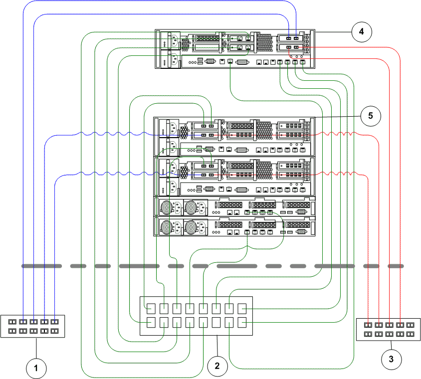
- Legend
-
1 SAN fabric switch A 2 Ethernet switch 3 SAN fabric switch B 4 Oracle MaxRep Replication Engine 5 Oracle FS System Controllers and Pilots (Drive Enclosures not shown)
The following figure provides information on the cable connections for an iSCSI configuration using SFP or optical connectors.
Figure 4: iSCSI configuration using SFP or optical connectors
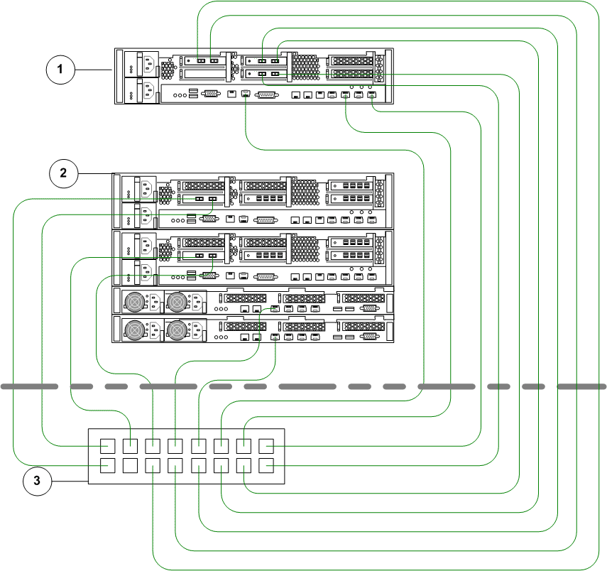
- Legend
-
1 Oracle MaxRep Replication Engine 2 Oracle FS System Controllers and Pilots ( Drive Enclosures not shown) 3 Ethernet switch
The following figure provides information on the cable connections for an FC and iSCSI configuration using SFP or optical connectors.
Figure 5: FC and iSCSI configuration using SFP or optical connectors
- Legend
-
1 SAN fabric switch A 2 Ethernet switch 3 SAN fabric switch B 4 Oracle MaxRep Replication Engine 5 Oracle FS System Controllers and Pilots ( Drive Enclosures not shown)