Replication Engine LED Indicators

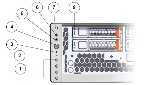
The LED alarm assembly is a high-level status indicator of the Replication Engine and Replication Engine components. Use these diagnostic LEDs to determine if a system component has failed. The LED alarm assembly also includes a power button to power on the Replication Engine.

The following figure shows the front display panel of the LED alarm assembly on the Replication Engine:

Figure 1: LED alarm assembly front display


LED alarm assembly front display

Legend
1 Alarm LEDs 2 Rear power supply LED
3 Service Processor (SP) LED 4 Power button
5 OK LED 6 Service Action Required LED or Fault LED
7 Locator LED 8 Hard drive status LED
The following table provides status information on the LEDs on the front display panel of the LED alarm assembly on the Replication Engine:
Table 1 Replication Engine LED status and description (front panel)
No. LED LED color Status
1

Alarm LEDs

  • Critical Alarm LED—Red

  • Major Alarm LED—Red

  • Minor Alarm LED—Amber

  • User Alarm LED—Amber

Indicate level of concern.

2

Rear power supply LED

Amber

Indicates a fault with one of the power supplies.

3

Service Processor (SP) LED

Green

Indicates these conditions:
  • Flashing: Indicates the SP is booting.
  • Steady: Indicates a steady state; no action required.
4

Power button

N/A

Used to power on, or power off, the Replication Engine.

5

OK LED

Green

Indicates these conditions:
  • Off: Indicates that the system is not running in its normal state.
  • Steady on: Indicates that the system is powered on and is running in its normal operating state.
  • Fast blink: Indicates that the system is running on standby mode and can be quickly returned to full function.
  • Slow blink: Indicates that a normal but transitory activity is taking place.
6

Service Action Required LED or Fault LED

Amber

  • Details will be present in the Oracle Integrated Lights Out Manager (ILOM).
  • In some cases, individual component LEDs indicate faulty performance.
7

Locator LED and button

White

This LED can be turned on to identify a particular system. When on, the LED blinks rapidly. Pressing and holding the Locator button for 5 seconds initiates a test of all LEDs in the LED assembly.

8

Hard drive status LED

  • Top LED—Blue
  • Middle LED—Amber
  • Bottom LED—Green
  • Ready to Remove LED (top): Indicates that the driver can be removed during a hot-plug operation.
  • Service Required LED (middle): Indicates that the drive has experienced a fault condition.
  • OK/Activity LED (bottom): Indicates the driver's availabilty for use. On indicates that read or write activity is in progress. Off indicates that the drive is idle and available for use.
The following figure shows the LEDs at the back of the Replication Engine:

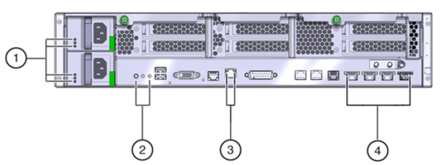
Figure 2: Replication Engine back LEDs


Replication Engine back LEDs

Legend
1 Power supply status LEDs 2 Chassis status LEDs
3 Network management LED 4 Net0 to Net3 status LEDs
The following table provides information on the LEDS on the back of the Replication Engine:
Table 2 Replication Engine LED status and description (back panel)
No. LED LED color Status
1

Power supply status LEDs

  • (Top) Output Power OK LED—Green

  • (Middle) Service Action Required LED—Amber

  • (Bottom) AC or DC Input Power OK LED—Green

  • Output Power OK LED: Indicates that output power is without fault.

  • Service Action Required LED: Indicates that service for the power supply is required.

  • AC or DC Input Power OK LED: Indicates that input power is without fault.

2

Chassis status LEDs

  • (Left) Locator LED and button—White

  • (Center) Service Action Required LED—Amber

  • (Right) Main Power OK LED—Green

  • Locator LED and button: The Locator LED can be turned on to identify a particular system.

  • Service Action Required LED: Indicates that service is required. Under some fault conditions, individual component fault LEDs are turned on in addition to the Service Action Required LED.

  • Main Power OK LED: Indicates these conditions:
    • Off: System is not running in its normal state. System power might be off. The SP might be running.

    • Steady on: System is powered on and is running in its normal operating state. No service actions are required.

    • Fast blink: System is running in standby mode and can be quickly returned to full function.

    • Slow blink: A normal but transitory activity is taking place. Slow blinking might indicate that system diagnostics are running or that the system is booting.

3

Network management LED

  • (Left) Link and Activity LED—Green

  • (Right) Speed LED—Green, amber, or off

Indicates these conditions:
  • Link and Activity LED:
    • On or blinking: A link is established.

    • Off: No link is established.

  • Speed LED:
    • On or blinking: The link is operating as a 100-Mbps connection.

    • Off : The link is operating as a 10-Mbps connection.

4

Net0 to Net3 status LEDs

  • (Left) Link and Activity LED—Green

  • (Right) Speed LED—Amber

Indicates the state of the service processor:
  • Link and Activity LED:
    • On or blinking: A link is established.

    • Off: No link is established.

  • Speed LED:
    • Amber: The link is operating as a Gigabit connection (1000-Mbps).

    • Green: The link is operating as a 100-Mbps connection.

    • Off: The link is operating as a 10-Mbps connection or there is no link.