4 Setting Up Layer 2 VPNs (VPLS)
This chapter explains how to set up a layer 2 VPN with a virtual private LAN service (VPLS) within your Cisco IOS or Juniper JUNOS-based networks.
About Layer 2 VPNs (VPLS)
An IP VPN is a means of creating a private network over a shared IP infrastructure. A VPN enables a secure, private connection between a number of geographically remote customer sites. VPNs can be used to implement corporate intranets, linking remote offices or mobile workers, and extranets, extending the services to customers, suppliers, or other communities of interest.
A VPLS is a way to provide Ethernet-based multipoint-to-multipoint communication over IP or MPLS networks. It allows geographically dispersed sites to share an Ethernet broadcast domain by connecting sites through pseudo-wires.
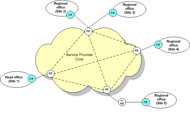
Figure 4-1 shows a network that connects all of a customer's sites so that those sites can exchange layer 2 communication that is separate from the communication traffic of other customers.
VPN Topology
The topology types for layer 2 VPNs (VPLS) are the following:
-
Point to point
-
Mesh
-
Hub and spoke
-
HVPLS
About Cross Connects
VPNs that use point-to-point topology use a cross connect, which connects an interface to a neighbor. A cross connect is a direct connection between two circuits, an attachment circuit and a remote PE device, using a pseudo-wire, which turns the two circuits into one circuit.
About VSIs
VPNs that use mesh and hub-and-spoke topologies use Virtual Switching Instances (VSIs) to control customer traffic by using MAC table details.
A VSI represents a single VSI on a PE device. You can create VSIs at the layer 2 site level, or an existing VSI can be inherited from a VSI profile, which is created at the layer 2 VPN level. A VSI profile allows you to manage common values across VSIs by allowing you to configure multiple sets of values that are inherited by instances of VSIs.
Before Setting Up a VPN (VPLS)
Before setting up a VPN for Juniper devices, you need to perform a pre-configuration task.
Pre-Configuration for Juniper Devices
Before setting up VPNs, some manual configuration of routers will likely be required. You must have your MPLS core set up to support VPNs. See the vendor documentation for details.
You must manually pre-configure Juniper devices to support the configuration of layer 2 VPNs in IP Service Activator. Configuration policies are available for layer 2 VPNs on Juniper devices. For information about installing and applying configuration policies, see IP Service Activator QoS User's Guide. For details about the configuration policies, see the IP Service Activator online Help.
Setting Up a Layer 2 VPN (VPLS)
To set up a VPN, you need to create a VPN object and link sites to it. If you are using Juniper devices, see "Pre-Configuration for Juniper Devices."
The following high-level steps are involved in setting up a layer 2 VPN (VPLS) within IP Service Activator:
Note:
The order of these high-level steps can vary, however you cannot modify layer 2 site details until the site is associated with the VPN and the interface is associated to the site.Creating a Layer 2 VPN
Create and configure the VPN before you add and configure the sites that you plan to associate with the VPN. You can then link the sites to the VPN object. For more information about layer 2 VPN property page details, see IP Service Activator online Help.
To create a layer 2 VPN:
-
In the Hierarchy pane, click the Service tab.
-
Expand the Customers folder.
-
Expand the folder for the customer for which you want to create a VPN.
-
Right-click the Layer 2 VPN folder, and select Add Layer 2 VPN.
The Layer 2 VPN dialog box opens.
-
In the Layer 2 VPN property page, enter the following:
-
Name: Enter a name for the layer 2 VPN. The name can contain only alphanumeric characters and cannot include spaces.
-
Signalling: Select a signalling type for the layer 2 VPN.
-
Discovery: Select a discovery type for the layer 2 VPN.
-
VPLS ID: Enter the VPLS ID for the layer 2 VPN.
-
-
Click the Topology property page and select one of the following typology types:
-
Point-to-Point: Sites can be configured only as cross-connects.
-
Hub and Spoke: Sites can be configured only as VSIs.
-
Mesh: Sites can be configured only as VSIs.
-
HVPLS: Site can be configured as cross-connects and VSIs.
The type of topology you select determines how you configure the sites, and the VPN.
-
-
For mesh, hub and spoke, and HVPLS topology types, do the following:
-
Click the Route Targets property page and enter route target details.
-
Click the VSI Profile property page and enter VSI profile details.
-
-
(Optional) Click the Ownership property page and enter details to restrict access to the layer 2 VPN object.
-
Click OK.
Creating Layer 2 Sites
After you create a layer 2 VPN, you can create a layer 2 site.
To create a layer 2 site:
-
In the Hierarchy pane, click the Service tab.
-
Expand the Customers folder.
-
Expand the folder for the customer for which you want to create a site.
-
Right-click the Layer 2 VPN folder, and select Add Layer 2 Site.
The Layer 2 Site dialog box opens.
-
Click the Site property page and enter the following:
-
Name: Specifies a name for the site.
-
Site ID: Specifies an ID for the site.
-
-
Click OK.
A layer 2 site is created, and is displayed in the customer folder.
Adding Interfaces to a Layer 2 Site
After you create the layer 2 site, add interfaces to the site.
To add an interface to a layer 2 site:
-
In the Hierarchy pane, click the Topology tab.
-
Expand the Devices folder.
-
Double-click a device to view its interfaces.
-
Return to the Hierarchy pane and click the Service tab.
-
In the Details pane, select the interface that you want to add to the layer 2 site.
-
Drag and drop the interface to the layer 2 site.
Adding Layer 2 Sites to Layer 2 VPNs
After you add at least one interface to a layer 2 site, add the layer 2 site to a layer 2 VPN.
To add a layer 2 site to a layer 2 VPN:
-
In the Hierarchy pane, select the layer 2 site that you want to add to a layer 2 VPN.
-
Drag and drop the layer 2 site to the layer 2 VPN.
If any values in the site contradict the topology of your VPN, you may be unable to add it to that VPN. Review topology and site details for compatibility.
Modifying Layer 2 Site Details
After you add the layer 2 site to the layer 2 VPN, modify the later 2 site properties according to the topology type of the VPN. For more information about layer 2 site property page details, see IP Service Activator online Help.
Configuring Layer 2 Point-to-Point VPNs
A point-to-point VPN uses cross connects. For more information, see "About Cross Connects."
To configure a point-to-point VPN using cross connects:
-
If you selected Point-to-Point from the list on the topology property page, create and configure the layer 2 VPN properties for a point-to-point VPN.
For more information, see the layer 2 VPN Properties topic in IP Service Activator online Help.
-
Create a site (Site 1) and enter a name and site ID.
-
Create another site (Site 2) and select and specify the necessary details.
-
Link an interface (Interface 1) to Site 1, and another interface (Interface 2) to Site 2.
-
Link Site 1 and Site 2 to the layer 2 VPN.
-
Modify Site 1 by creating a cross-connect for the interface that you added to Site 1, and adding it to the Site 2 device.
-
Modify Site 2 by selecting the cross-connect for the interface that you added to Site 2, and adding it to the Site 2 device.
-
Specify a neighbor IP address on each site.
-
Click Set to save your changes.
Configuring Layer 2 Mesh or Hub and Spoke VPNs
VPNs that use mesh and hub-and-spoke topologies use VSIs to control customer traffic by using MAC table details. For more information, see "About VSIs."
In a mesh VPN, each site can communicate with all other sites. In a hub and spoke VPN, one or more sites act as a controlling interface.
To create and configure a mesh or hub-and-spoke VPN using VSIs:
-
Create a layer 2 VPN.
-
Create a site by entering the name and site ID.
-
Link an interface to the site.
-
Link the site to the VPN.
-
In the Layer 2 VPN property pages, do one of the following:
-
If you selected Mesh from the list on the topology property page, select or specify the details for a mesh VPN.
-
If you selected Hub and Spoke from the list on the topology property page, select or specify the details for a hub-and-spoke VPN, including selecting hub sites from the list.
-
-
Modify the site by doing one of the following:
-
Create a VSI for the interface.
-
Choose to inherit from the default VSI profile, if there is one.
-
-
Click the Set button to save your changes.
Configuring Layer 2 HVPLS VPNs
An HVPLS VPN is a hierarchical network where network PEs (N-PEs) form a fully meshed VPLS network connected to user-facing PEs (U-PEs) using pseudo-wires. HVPLS VPNs make use of cross connects and VSIs. There are many configurations for HVPLS VPNs. The procedure in this section outlines the high-level steps for creating an HVPLS VPN. For more information, see "VPN Topology."
To create and configure an HVPLS VPN using VSIs and cross connects:
-
Create the VPN and sites.
-
Specify which sites are mesh.
-
Create the cross connects on the spoke sites.
-
Create the VSIs on the mesh sites.
-
On the HVPLS tab of the layer 2 mesh site, assign the appropriate cross connects to the selected device to create the connection.
Note:
When an interface in a HVPLS site has a VSI configured on it, the site's device is available on the HVPLS tab. Cross connects that are not associated to the mesh are available and you can assign them to the device.
Implementing the VPN
After the site and VPN details are set up and the relevant devices are managed, the entire configuration can be applied by committing the transaction.
When you commit the transaction, any concrete VPNs that will be created are listed in the Concretes property page of the Transaction dialog box.
Any validation errors are reported in the Fault property page of the Transaction dialog box and the Current Faults pane.
To cancel the transaction after reviewing the concrete VPNs that will be created and the faults generated by the transaction, click Cancel.
To proceed with the transaction, click OK. Configuration details are sent to the Network Processor and on to the applicable cartridge. For information about committing a transaction, see IP Service Activator User's Guide.
Use the built-in transaction status monitoring feature to track the provisioning status of the transaction. Optionally, once the transaction is provisioned successfully, if the device is managed by the Network Processor, you can perform a device audit.
For details on transaction monitoring, and performing audits, see IP Service Activator System Administrator's Guide.
Viewing Implemented VPNs
You can view a list of the VPNs that have been propagated to the network and installed on an interface or subinterface.
To view implemented VPN details in the IP Service Activator client:
-
In the Hierarchy pane, select the Service tab.
-
Expand the Customer folder and select the required customer from the displayed customer list.
The list of related sites and VPNs is displayed.
-
Expand the VPNs folder.
The list of implemented VPNs is displayed.
-
Double-click the required VPN.
The Details pane for that VPN is displayed on the right.
-
In the Details pane, click the VPNs tab to view VPNs implemented on the selected object. All concrete VPNs appear on a yellow background.
VPN details are listed under the following headings:
-
VPN: Name of the VPN.
-
Site: Site associated with the VPN.
-
Access Point: Interface or sub-interface associated with the site.
-
Device: This column remains blank for MPLS VPNs.
-
State: Current state of the VPN and is one of the following:
-
Inactive: VPN has been created but has not been propagated to the proxy agents.
-
Active: VPN has been propagated to the proxy agents.
-
Rejected: VPN configuration was rejected.
-
Installed: VPN configuration has been installed on the designated device.
-
-
Conflict: There is a configuration error in the VPN.
-
ID: Internal ID number by which the VPN is identified.
-
Viewing the Statistics Summary
You can see the inactive, active, installed, and failed states by viewing the Statistics Summary.
To view the Statistics Summary:
-
When the Details pane for an implemented VPN is open, click View in the menu bar.
-
Select Statistics Summary.
The Statistics Summary for that VPN is displayed at the bottom of the Details pane.