1 Getting Started
This chapter describes how to get started with your Oracle Exalytics In-Memory Machine.
It discusses the following topics:
1.1 Tools and Equipment Needed
To install the system, you need the following tools:
-
No. 2 Phillips screwdriver
-
ESD mat and grounding strap
-
Pencil, stylus, or other pointed device, for pushing front panel buttons
You also need a system console device, such as one of the following:
-
A laptop or Sun workstation
-
ASCII terminal
-
Terminal server
1.2 Installation Tasks
This section summarizes a list of tasks that you must perform to install the Oracle Exalytics In-Memory Machine.
Table 1-1 Server Installation Tasks
| Step | Description | For More Information |
|---|---|---|
|
1 |
Unpack the machine and any optional components ordered for the Oracle Exalytics In-Memory Machine from the shipping containers. |
See Opening the Box |
|
2 |
Review electrostatic damage (ESD) precautions before installing the Oracle Exalytics In-Memory Machine. |
See ESD Precautions |
|
2 |
Install the Oracle Exalytics In-Memory Machine into a rack using slide-rails. |
See Installing Oracle Exalytics In-Memory Machine Into a Rack |
|
3 |
Connect cables to the server. |
|
|
4 |
Connect power cords. |
1.3 Opening the Box
Carefully open the shipping box. Unpack all server components from the packing cartons.
After opening the box, verify the server box contents and any optional components.
1.3.1 Server Box Contents
The server box should contain the following items:
-
Oracle Sun Server X4-4
-
Power cord, packaged separately with country kit
-
Rackmount kit containing rack rails and installation instructions
-
(Optional) Oracle Sun Server X4-4 Server Documentation and Media Kit, including the following:
-
License and safety documentation
-
Tools and Drivers DVD (includes drivers and additional software), Oracle Hardware Installation Assistant CD, and SunVTS CD
-
1.4 ESD Precautions
Electronic equipment is susceptible to damage by static electricity. Use a grounded antistatic wrist strap, foot strap, or equivalent safety equipment to prevent electrostatic damage (ESD) when you install or service the Oracle Exalytics In-Memory Machine.
Caution:
To protect electronic components from electrostatic damage, which can permanently disable the system or require repair by authorized service technicians, place components on an antistatic surface, such as an antistatic discharge mat, an antistatic bag, or a disposable antistatic mat. Wear an antistatic grounding strap connected to a metal surface on the chassis when you work on system components.1.5 Oracle Exalytics In-Memory Machine Description
This section shows the connectors and buttons on the front and back panels of the Oracle Exalytics In-Memory Machine.
It contains the following topics:
1.5.1 Front Panel Features
Figure 1-1 shows the front panel of the Oracle Exalytics In-Memory Machine.
Figure 1-1 Oracle Exalytics In-Memory Machine Front Panel
Description of "Figure 1-1 Oracle Exalytics In-Memory Machine Front Panel"
Table 1-2 describes the front panel buttons and LED indicators.
| Number | Description |
|---|---|
|
1 |
Locator LED/Locator button: white |
|
2 |
Service Action Required LED: amber |
|
3 |
Main Power/OK LED: green |
|
4 |
Power button |
|
5 |
SP OK/Fault LED: green/amber |
|
6 |
Service Action Required LEDs (3) for Fan Module (FAN), Processor (CPU) and Memory: amber |
|
7 |
Power Supply (PS) Fault (Service Action Required) LED: amber |
|
8 |
Over Temperature Warning LED: amber |
|
9 |
USB 2.0 connectors (2) |
|
10 |
DB-15 video connector |
|
11 |
Hard disk drive 0 |
|
12 |
Hard disk drive 1 |
|
13 |
Hard disk drive 2 |
|
14 |
Hard disk drive 3 |
|
15 |
Hard disk drive 4 |
|
16 |
Hard disk drive 5 |
1.5.2 Back Panel Features
Figure 1-2 and Figure 1-3 shows the back panel of the Oracle Exalytics In-Memory Machine X2-4, and Oracle Exalytics In-Memory Machine X3-4, respectively.
Figure 1-2 Oracle Exalytics In-Memory Machine X2-4 Back Panel
Description of "Figure 1-2 Oracle Exalytics In-Memory Machine X2-4 Back Panel"
Figure 1-3 Oracle Exalytics In-Memory Machine X3-4 Back Panel
Description of "Figure 1-3 Oracle Exalytics In-Memory Machine X3-4 Back Panel"
Table 1-3 describes the back panel buttons and LED indicators.
| Number | Description |
|---|---|
|
1 |
Power supply unit 0 status indicator LEDs: Service Action Required: amber DC OK: green AC OK: green or amber |
|
2 |
Power supply unit 0 AC inlet |
|
3 |
Power supply unit 1 status indicator LEDs: Service Action Required: amber DC OK: green AC OK: green or amber |
|
4 |
Power supply unit 1 AC inlet |
|
5 |
System status LEDs: Power/OK: green Attention: amber Locate: white |
|
6 |
PCIe card slots 0–4 |
|
7 |
Cluster card slot |
|
8 |
Network (NET) 10/100/1000 ports: NET0–NET3 |
|
9 |
USB 2.0 connectors (2) |
|
10 |
PCIe card slots 5–9 |
|
11 |
Service processor (SP) network management ( |
|
12 |
Serial management ( |
|
13 |
DB-15 video connector |
Figure 1-4 Oracle Exalytics In-Memory Machine X5-4 and X4-4 Back Panel
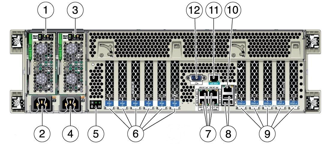
Description of "Figure 1-4 Oracle Exalytics In-Memory Machine X5-4 and X4-4 Back Panel"
Table 1-3 describes the back panel buttons and LED indicators on the Oracle Exalytics In-Memory Machine X5-4 and X4-4 Back Panel.
Table 1-4 Figure Legend for Oracle Exalytics In-Memory Machine X5-4 and X4-4 Back Panel
| Number | Description |
|---|---|
|
1 |
Power supply unit 0 status indicator LEDs: Service Action Required: amber DC OK: green AC OK: green or amber |
|
2 |
Power supply unit 0 AC inlet |
|
3 |
Power supply unit 1 status indicator LEDs: Service Action Required: amber DC OK: green AC OK: green or amber |
|
4 |
Power supply unit 1 AC inlet |
|
5 |
System status LEDs: Power/OK: green Attention: amber Locate: white |
|
6 |
PCIe card slots 1–6 |
|
7 |
Network (NET) 10/100/1000 ports: NET0–NET3 |
|
8 |
USB 2.0 connectors (2) |
|
9 |
PCIe card slots 7–11 |
|
10 |
Service processor (SP) network management ( |
|
11 |
Serial management ( |
|
12 |
DB-15 video connector |
1.6 Connecting the Cables
Connect cables to the Oracle Exalytics In-Memory Machine as follows:
-
Connect an Ethernet cable to the Gigabit Ethernet (
NET0) connectors as needed for operating system support. See the part 8 in Figure 1-2. -
(Optional) If you want to interact with the system console directly, connect any external devices, such as a mouse and keyboard, to the server's USB connectors, or a monitor to the DB-15 video connector. See parts 9 and 13 in Figure 1-2.
-
If you plan to configure network IP address for Oracle Integrated Lights Out Manager (ILOM), connect an Ethernet cable to the Ethernet port labeled
SER MGT. See the part 12 in Figure 1-2. -
If you plan to access the ILOM command-line interface (CLI) using the serial management port, connect a serial null modem cable to the RJ-45 serial port labeled
SER MGT. See the part 12 in Figure 1-2.
1.7 Connecting the Power Cords
Connect the power cords to the Oracle Exalytics In-Memory Machine as follows:
-
Connect two grounded server power cords to grounded electrical outlets.
-
Connect the two server power cords to the AC connectors on the back panel of the server.
When power is connected, the server boots into standby power mode. In standby power mode, the SP OK/Fault LED flashes, but the main Power/OK LED remains off. After a few minutes, the main Power/OK LED slowly flashes the standby pattern, indicating the service processor (SP) is working. Note that the server is not initialized or powered on yet.
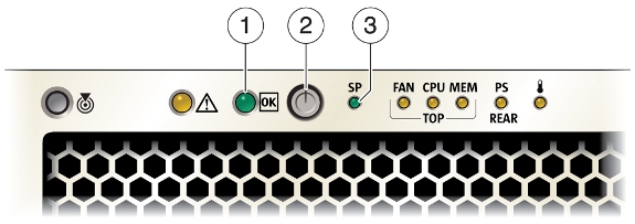
1 - Power/OK LED
2 - Power button
3 - SP OK/Fault LED